Danfoss H1 Basic Information
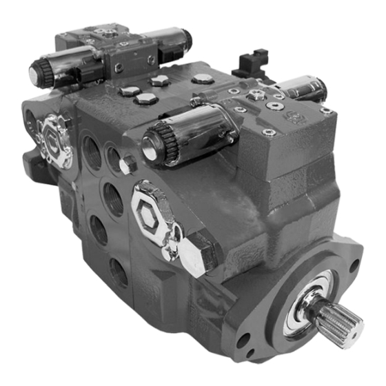
Axial piston pumps
Hide thumbs
Also See for H1:
- Technical information (144 pages) ,
- Service manual (72 pages) ,
- Technical information (52 pages)

Subscribe to Our Youtube Channel
Related Manuals for Danfoss H1


Summary of Contents for Danfoss H1
- Page 1 Basic Information H1 Axial Piston Pumps Single and Tandem powersolutions.danfoss.com...
- Page 2 Basic Information H1 Axial Piston Pumps, Single and Tandem Revision history Table of revisions Date Changed April 2017 NFPE and AC controls added. 0602 May 2016 Updated to Engineering Tomorrow design. 0601 Nov 2010-Nov 2015 Various changes. BA-0501 Jul 2009 First edition.
-
Page 3: Table Of Contents
Basic Information H1 Axial Piston Pumps, Single and Tandem Contents Danfoss hydrostatic product family A word about the organization of this manual........................4 General description of H1 family hydrostatic pumps......................4 Overview of H1 pumps technical specifications........................5 H1 pumps literature reference..............................6 Operation Pressure limiter valves.................................. -
Page 4: Danfoss Hydrostatic Product Family
Danfoss hydrostatic product family A word about the organization of this manual General information covering all displacements of the H1 range is given in the beginning of this manual. This includes definitions of operating parameters and system design considerations. The next sections in the book detail the specific operating limitations for each frame and give a full breakdown of available displacements, features and options. -
Page 5: Overview Of H1 Pumps Technical Specifications
H1 Axial Piston Pumps, Single and Tandem Danfoss hydrostatic product family Overview of H1 pumps technical specifications The table below shows the available range of H1 pumps as of this printing, with their respective speed, pressure, weight and mounting flange: Feature 45.0... -
Page 6: H1 Pumps Literature Reference
Basic Information H1 Axial Piston Pumps, Single and Tandem Danfoss hydrostatic product family H1 pumps literature reference Available literature for H1 Pumps Literature Type Order number Title H1 Axial Piston Pumps, Single and Tandem Product Line Overview L1012919 AM00000001en-US H1 Axial Piston Pumps, Single and Tandem... -
Page 7: Operation
High Pressure Relief Valve (HPRV) and charge check All H1 pumps are equipped with a combination high pressure relief and charge check valve. The high- pressure relief function is a dissipative (with heat generation) pressure control valve for the purpose of limiting excessive system pressures. -
Page 8: Bypass Function
Basic Information H1 Axial Piston Pumps, Single and Tandem Operation Bypass function The single pump HPRV valve also provides a loop bypass function when each of the two HPRV hex plugs are mechanically backed out 3 full turns. Engaging the bypass function mechanically connects both A & B sides of the working loop to the common charge gallery. -
Page 9: Charge Pressure Relief Valve (Cprv)
Basic Information H1 Axial Piston Pumps, Single and Tandem Operation Charge Pressure Relief Valve (CPRV) The charge pressure relief valve is a direct acting poppet valve which opens and discharges fluid to the pump case when pressure exceeds a designated level. The charge pressure relief valve maintains charge pressure at a designated level above case pressure. -
Page 10: Electrical Displacement Control (Edc)
Basic Information H1 Axial Piston Pumps, Single and Tandem Operation Electrical Displacement Control (EDC) EDC principle An EDC is a displacement (flow) control. Pump swashplate position is proportional to the input command and therefore vehicle or load speed (excluding influence of efficiency), is dependent only on the prime mover speed or motor displacement. -
Page 11: Manual Displacement Control (Mdc)
Basic Information H1 Axial Piston Pumps, Single and Tandem Operation Manual Displacement Control (MDC) MDC principle An MDC is a Manual proportional Displacement Control (MDC). The MDC consists of a handle on top of a rotary input shaft. The shaft provides an eccentric connection to a feedback link. -
Page 12: Automotive Control (Ac)
P005 702 Automotive Control (AC) The AC-1 and AC-2 propel transmission system consists of an H1 variable pump, embedded electronic controller, and service tool configurable PLUS+1® software that allows the customer to completely optimize vehicle performance. The embedded electronic controller provides an electric input signal activating one of two solenoids that port charge pressure to either side of the pump servo cylinder. -
Page 13: Automotive Control Connection Diagram
Basic Information H1 Axial Piston Pumps, Single and Tandem Operation Automotive Control connection diagram DEUTSCH connector DTM/12 pin Battery (-) CC1p01 Battery (+) CC1p02 Sensor (+) CC1p03 CC1p03 Motor RPM/Direction Sensor (-) CC1p04 CC1p04 Motor RPM Input (Frequency) CC1p05 e.g. -
Page 14: Forward-Neutral-Reverse (Fnr) Electric Control
Basic Information H1 Axial Piston Pumps, Single and Tandem Operation Forward-Neutral-Reverse (FNR) electric control The 3-Position (F-N-R) control uses an electric input signal to switch the pump to a full stroke position. Under some circumstances, such as contamination, the control spool could stick and cause the pump to stay at some displacement. -
Page 15: Fan Drive Control (Fdc)
Basic Information H1 Axial Piston Pumps, Single and Tandem Operation Fan Drive Control (FDC) The Fan Drive Control (FDC) is a non-feedback control in which an electrical input signal activates the proportional solenoid that ports charge pressure to either side of the pump servo cylinder. -
Page 16: Manual Over Ride (Mor)
Basic Information H1 Axial Piston Pumps, Single and Tandem Operation Manual Over Ride (MOR) All controls are available with a Manual Over Ride (MOR) either standard or as an option for temporary actuation of the control to aid in diagnostics. -
Page 17: Swash Plate Angle Sensor For Nfpe And Ac2 Controls
Basic Information H1 Axial Piston Pumps, Single and Tandem Operation Swash plate angle sensor for NFPE and AC2 controls The angle sensor detects the swash plate angle position and direction of rotation from the zero position. The swash angle sensor works on the AMR sensing technology. Under the saturated magnetic field, the resistance of the element varies with the magnetic field direction. -
Page 18: Control-Cut-Off Valve (Cco Valve)
Basic Information H1 Axial Piston Pumps, Single and Tandem Operation Control-Cut-Off valve (CCO valve) The pump offers an optional control cut off valve integrated into the control. This valve will block charge pressure to the control, allowing the servo springs to de-stroke both pumps regardless of the pump´s primary control input. -
Page 19: Displacement Limiter
H1 Axial Piston Pumps, Single and Tandem Operation Displacement limiter All H1 pumps are designed with optional mechanical displacement (stroke) limiters factory set to max. displacement. The maximum displacement of the pump can be set independently for forward and reverse using the two adjustment screws to mechanically limit the travel of the servo piston down to 50 % displacement. -
Page 20: Speed And Temperature Sensor
Function of the speed sensor is to detect the shaft speed and the direction of rotation. Typically the sensor will be mounted to the housing of a Danfoss pump or motor and senses the speed from a target ring that is rotating inside the pump or motor. Because of the digital output signals for speed and direction and a non speed dependent output voltage level, the sensor is ideal for high and low speed measurements. - Page 21 Basic Information H1 Axial Piston Pumps, Single and Tandem Operation Ordering data Description Quantity Ordering number Mating connector DT06-6S Wedge lock WM65 Socket contact (16 and 18 AWG) 0462-201-2031 Danfoss mating connector kit 11033865 Temperature sensor data Parameter Minimum Maximum Temperature range -40 ±...
-
Page 22: Operating Parameters
Basic Information H1 Axial Piston Pumps, Single and Tandem Operating parameters Input speed Minimum speed is the lowest input speed recommended during engine idle condition. Operating below minimum speed limits the pump’s ability to maintain adequate flow for lubrication and power transmission. -
Page 23: Servo Pressure
Size drain plumbing accordingly. Auxiliary Pad Mounted Pumps. The auxiliary pad cavity of H1 pumps configured without integral charge pumps is referenced to case pressure. Units with integral charge pumps have auxiliary mounting pad cavities referenced to charge inlet (vacuum). -
Page 24: External Shaft Seal Pressure
The minimum temperature relates to the physical properties of component materials. Size heat exchangers to keep the fluid within these limits. Danfoss recommends testing to verify that these temperature limits are not exceeded. Viscosity For maximum efficiency and bearing life, ensure the fluid viscosity remains in the recommended range. -
Page 25: System Design Parameters
Basic Information H1 Axial Piston Pumps, Single and Tandem System design parameters Filtration system To prevent premature wear, ensure only clean fluid enters the hydrostatic transmission circuit. A filter capable of controlling the fluid cleanliness to ISO 4406 class 22/18/13 (SAE J1165) or better, under normal operating conditions, is recommended. -
Page 26: Filtration
We recommend a filter bypass with a filter bypass sensor to prevent damage due to blocked suction filters. Charge pressure filtration (full charge pump flow) For most H1 pumps exist two types of pressure filtration: • remote pressure filtration (filter remotely mounted on vehicle) •... - Page 27 Integral charge pressure filtration The H1 integral pressure filter head is designed with a filter bypass valve and noncontacting bypass sensor. The pressure differential acting on the filter element also acts on a spring biased bypass spool.
- Page 28 Socket terminal Deutsch 0462-201-20141 Danfoss mating connector kit 11031205 The H1 pumps with an integrated filter option are shipped with a filter of length as indicated: H1 pump size Filter element length Filter order number H1P 069, 078, 089 and 100...
- Page 29 Basic Information H1 Axial Piston Pumps, Single and Tandem System design parameters Filter bypass characteristic (completely blocked element) [31.70] Filter bypass sensor activated [26.42] [21.13] [15.85] [10.57] [5.28] [29] [58] [87] [116] [145] [174] [203] [232] [261] [290] [319] Differential pressure over filter bypass...
-
Page 30: Fluid Selection
Case drain All single H1 pumps are equipped with multiple drain ports whereas some H1 pumps are equipped with two case drain port sizes. Port selection and case drain routing must enable the pump housing to maintain a volume of oil not less than half full and normal operating case pressure limits of the unit are maintained. -
Page 31: Charge Pump
System design parameters Charge pump Charge flow is required on all H1 pumps applied in closed circuit installations. The charge pump provides flow to make up internal leakage, maintain a positive pressure in the main circuit, provide flow for cooling and filtration, replace any leakage losses from external valving or auxiliary systems, and to provide flow and pressure for the control system. -
Page 32: Bearing Loads And Life
Tables are available in the Controls section of each H1 size specific technical information that illustrates the flow out port as a function of pump rotation and energized EDC solenoid. -
Page 33: Mounting Flange Loads
Basic Information H1 Axial Piston Pumps, Single and Tandem System design parameters Mounting flange loads Adding tandem mounted auxiliary pumps and/or subjecting pumps to high shock loads may result in excessive loading of the mounting flange. Applications which experience extreme resonant vibrations or shock may require additional pump support. -
Page 34: Shaft Torque
Basic Information H1 Axial Piston Pumps, Single and Tandem System design parameters Shaft torque The rated torque is a measure of tooth wear and is the torque level at which a normal spline life of 2 x 10⁹ shaft revolutions can be expected. The rated torque presumes a regularly maintained minimum level of lubrication via a moly-disulfide grease in order to reduce the coefficient of friction and to restrict the presence of oxygen at the spline interface. -
Page 35: Shaft Availability And Torque Ratings
P003 333E CAUTION Ensure requirements do not exceed shaft torque ratings. Torque required by auxiliary pumps is additive. Rated and maximum torque ratings for each available shaft is shown in the H1 size specific technical information. 11062168 | BC00000057en-US0602 | 35 ©... -
Page 36: Understanding And Minimizing System Noise
Basic Information H1 Axial Piston Pumps, Single and Tandem System design parameters Understanding and minimizing system noise Noise is transmitted in fluid power systems in two ways: as fluid borne noise, and structure borne noise. Fluid-borne noise (pressure ripple or pulsation) is created as pumping elements discharge oil into the pump outlet. -
Page 37: Determination Of Nominal Pump Sizes
Basic Information H1 Axial Piston Pumps, Single and Tandem System design parameters Determination of nominal pump sizes Generally, the sizing process is initiated by an evaluation of the machine system to determine the required motor speed and torque to perform the necessary work function. - Page 38 Basic Information H1 Axial Piston Pumps, Single and Tandem 11062168 | BC00000057en-US0602 38 | © Danfoss | April 2017...
- Page 39 Basic Information H1 Axial Piston Pumps, Single and Tandem 11062168 | BC00000057en-US0602 | 39 © Danfoss | April 2017...
- Page 40 Phone: +86 21 3418 5200 Danfoss can accept no responsibility for possible errors in catalogues, brochures and other printed material. Danfoss reserves the right to alter its products without notice. This also applies to products already on order provided that such alterations can be made without changes being necessary in specifications already agreed.
Need help?
Do you have a question about the H1 and is the answer not in the manual?
Questions and answers