Danfoss H1 Technical Information
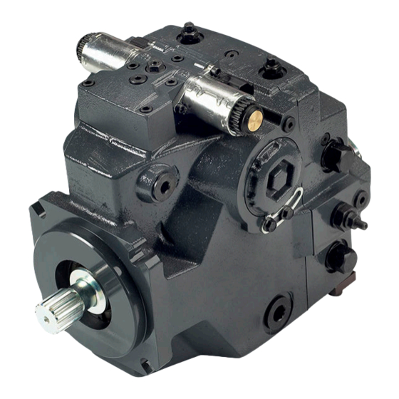
Axial piston single pumps; size 069/078
Hide thumbs
Also See for H1:
- Technical information (144 pages) ,
- Service manual (72 pages) ,
- Basic information (40 pages)

Related Manuals for Danfoss H1


Summary of Contents for Danfoss H1
- Page 1 MAKING MODERN LIVING POSSIBLE Technical Information H1 Axial Piston Single Pumps Size 069/078 powersolutions.danfoss.com...
- Page 2 Technical Information H1 Axial Piston Single Pumps, Size 069/078 Revision history Table of revisions Date Changed November 2015 Master Model Code changes. 0700 September 2014 MDC, CCO, and Swash Angle Sensor options added March 2014 Converted to Danfoss layout - DITA CMS...
-
Page 3: Table Of Contents
Technical Information H1 Axial Piston Single Pumps, Size 069/078 Contents Technical specifications H1P general specifications................................5 Technical data H1P 069/078.................................5 Operating parameters H1P 069/078............................6 Fluid specifications H1P ................................6 External radial shaft loads................................7 Bearing life H1P 069/078................................7 Mounting flange loads H1P 069/078............................7 Charge pump..................................... - Page 4 Tapered shaft customer acknowledgement........................42 H1P Auxiliary mounting, option H2 (SAE A, 9 teeth)......................43 H1P Auxiliary mounting, option H1 (SAE A, 11 teeth) ..................... 44 H1P Auxiliary mounting, option H3 (SAE B, 13 teeth) ......................45 H1P Auxiliary mounting, option H5 (SAE B-B, 15 teeth) ....................46 H1P Auxiliary mounting, option H6 (SAE C, 14 teeth) .....................
-
Page 5: H1P General Specifications
Technical Information H1 Axial Piston Single Pumps, Size 069/078 Technical specifications For definitions of the following specifications, see H1 Axial Piston Pumps, Basic Information 11062168, chapter Operating parameters. H1P general specifications Axial piston pump of cradle swashplate design with variable displacement... -
Page 6: Operating Parameters H1P 069/078
Technical Information H1 Axial Piston Single Pumps, Size 069/078 Technical specifications Operating parameters H1P 069/078 Feature Size 069/078 500 min (rpm) Input speed Minimum for internal charge supply. (at minimum charge/ 500 min (rpm) Minimum for external charge supply. control pressure) -
Page 7: External Radial Shaft Loads
= 109 N•m [965 lbf•in] All external shaft loads affect bearing life. In applications with external shaft loads, minimize the impact by positioning the load at 0° or 180° as shown in the figure. Danfoss recommends clamp-type couplings for applications with radial shaft loads. - Page 8 = 3700 N•m [32 750 lbf•in] Shock load moment: = 7900 N•m [69 920 lbf•in] P001 916 For more information, see H1 Axial Piston Pumps, Basic Information 11062168, the section “Mounting flange loads”. 11062169 • Rev 0700 • November 2015...
-
Page 9: Charge Pump
Multiple low speed high torque motors • High input shaft speeds Contact your Danfoss Power Solutions representative for application assistance if your application includes any of these conditions. Charge pump flow and power curves, 14/17 cm³ Charge pressure: 20 bar [290 psi] Viscosity: 11 mm²/s [63 SUS]... - Page 10 Technical Information H1 Axial Piston Single Pumps, Size 069/078 Master model code H1P 069/078 Displacement 69.2 cm [4.22 in 78.1 cm [4.77 in A – Rotation Left hand (counter clockwise) Right hand (clockwise) B – Product version Revision code Z – Port configuration Inch, Customer O-ring port sealing according to ISO 11926-1 D –...
- Page 11 Technical Information H1 Axial Piston Single Pumps, Size 069/078 Master model code H1P 069/078 D – Controls (continued) Code Control type CCO, NSS Connector — — Neutral Start Switch Deutsch 12V CCO Deutsch MDC — Manual Displacement Control 24V CCO...
-
Page 12: Master Model Code H1P 069/078
Technical Information H1 Axial Piston Single Pumps, Size 069/078 Master model code H1P 069/078 G – Endcap options (Twin port, ISO 6162 split flange ports) Align with options T – Filtration (below) and K – Auxiliary mounting pads: • ISO 3019-1, flange 82–2 (SAE A, 9 and 11 teeth) •... - Page 13 420 bar [6090 psi] 450 bar [6526 psi] L, F – with pressure limiter; K – without pressure limiter. Please contact Danfoss Power Solutions for pressures not shown or for applied pressure above max. working pressure (see Operating parameters H1P 069/078 on page 6).
- Page 14 Technical Information H1 Axial Piston Single Pumps, Size 069/078 Master model code H1P 069/078 S – Charge pump 14 cm³/rev [0.85 in³/rev] 17 cm³/rev [1.03 in³/rev] No charge pump, external charge supply (Align with options: E and T) T – Filtration (Align with option G: Endcap selection)
- Page 15 Technical Information H1 Axial Piston Single Pumps, Size 069/078 Master model code H1P 069/078 Y – Special settings (SIL2 non-certifiable, without customer files) Code CAN J1939 ECO fuel saving Functional Cruise control Control AC type mode option in/out – (12 V in/out –...
-
Page 16: Control Options
Technical Information H1 Axial Piston Single Pumps, Size 069/078 Control options Electrical Displacement Control (EDC), options: A2 (12 V) / A3 (24 V) The Electrical Displacement Control (EDC) consists of a pair of proportional solenoids on each side of a three-position, four-way porting spool. -
Page 17: Edc Solenoid Data
For coil location see Installation drawings. Control response H1 controls are available with optional control passage orifices to assist in matching the rate of swashplate response to the application requirements (e.g. in the event of electrical failure). The time required for the pump output flow to change from zero to full flow (acceleration) or full flow to zero (deceleration) is a net function of spool porting, orifices, and charge pressure. -
Page 18: Response Time Edc 069/078
Technical Information H1 Axial Piston Single Pumps, Size 069/078 Control options Typical response times shown below at the following conditions: (continued) Charge pressure 20 bar [290 psi] Speed 1800 min (rpm) Response time EDC 069/078 Stroking direction 0.8 mm [0.03 in] Orifice 1.3 mm [0.05 in] Orifice... -
Page 19: Manual Displacement Control (Mdc)
Technical Information H1 Axial Piston Single Pumps, Size 069/078 Control options Manual Displacement Control (MDC) MDC principle An MDC is a Manual proportional Displacement Control (MDC). The MDC consists of a handle on top of a rotary input shaft. The shaft provides an eccentric connection to a feedback link. This link is connected on its one end with a porting spool. -
Page 20: Mdc General Information
As seen from shaft side. Control response H1 controls are available with optional control passage orifices to assist in matching the rate of swashplate response to the application requirements (e.g. in the event of electrical failure). The time required for the pump output flow to change from zero to full flow (acceleration) or full flow to zero (deceleration) is a net function of spool porting, orifices, and charge pressure. -
Page 21: Response Time, Mdc 069/078
H1 Axial Piston Single Pumps, Size 069/078 Control options H1 pumps are limited in mechanical orificing combinations. Mechanical servo orifices are to be used only for fail-safe return to neutral in the event of an electrical failure. Typical response times shown below at the following conditions: ∆p... -
Page 22: Case Gauge Port M14
Technical Information H1 Axial Piston Single Pumps, Size 069/078 Control options Connector P003 480 Connector ordering data Description Quantity Ordering number Mating connector Deutsch® DT06-2S Wedge lock Deutsch® W2S Socket contact (16 and 18 AWG) Deutsch® 0462-201-16141 Danfoss mating connector kit... -
Page 23: Forward-Neutral-Reverse Electric Control (Fnr), Options: A9 (12 V) And B1 (24 V)
Technical Information H1 Axial Piston Single Pumps, Size 069/078 Control options Forward-Neutral-Reverse electric control (FNR), options: A9 (12 V) and B1 (24 V) The 3-position FNR control uses an electric input signal to switch the pump to a full stroke position. -
Page 24: Control Response
49. Control response H1 controls are available with optional control passage orifices to assist in matching the rate of swashplate response to the application requirements (e.g. in the event of electrical failure). The time required for the pump output flow to change from zero to full flow (acceleration) or full flow to zero (deceleration) is a net function of spool porting, orifices, and charge pressure. -
Page 25: Non Feedback Proportional Electric Control (Nfpe), Options: A8 (12 V) / B8 (24 V)
Technical Information H1 Axial Piston Single Pumps, Size 069/078 Control options Non Feedback Proportional Electric Control (NFPE), options: A8 (12 V) / B8 (24 V) The Non Feedback Proportional Electric (NFPE) control is an electrical automotive control in which an electrical input signal activates one of two proportional solenoids that port charge pressure to either side of the pump servo cylinder. -
Page 26: Control Response
For coil location see Installation drawings. Control response H1 controls are available with optional control passage orifices to assist in matching the rate of swashplate response to the application requirements (e.g. in the event of electrical failure). The time required for the pump output flow to change from zero to full flow (acceleration) or full flow to zero (deceleration) is a net function of spool porting, orifices, and charge pressure. -
Page 27: Response Time, Nfpe 069/078
Technical Information H1 Axial Piston Single Pumps, Size 069/078 Control options Typical response times shown below at the following conditions: ∆p 250 bar [3626 psi] Viscosity and temperature 30 mm²/s [141 SUS] and 50 °C [122 °F] 20 bar [290 psi]... -
Page 28: Automotive Control (Ac)
Control options Automotive Control (AC) The H1 Automotive Control (AC) is an electric NFPE Control with an integrated microcontroller, installed on the pump. The integrated microcontroller enhanced control performance with a flexible, configurable control scheme for an entire single path propel transmission. It can be used in combination with fixed and variable displacement hydraulic-motors. -
Page 29: Performance Functions
Installation features • Factory calibration for hysteresis compensation. • Starting current adjustment in the factory • Pre-installed application software and parameter files Refer to the Technical Information, H1 Automotive Control L1223856 for more details. 11062169 • Rev 0700 • November 2015... -
Page 30: Fan Drive Control (Fdc), Options: F1 (12V) / F2 (24V)
P301 441 H1 pumps with FDC will be delivered from factory with nominal PL setting of 150 bar [2175 psi]. The PL must be re-adjusted to ensure that the fan reaches the desired fan speed to satisfy the cooling needs of the system. - Page 31 Technical Information H1 Axial Piston Single Pumps, Size 069/078 Control options Pump displacement vs. control current Forward 100% H1 FDC control Max Current a = Forward Threshold b = Reverse Threshold N = Neutral Override Current 100% Signal Current (mA(DC...
-
Page 32: Control Response
Loss of input signal to this control will cause the pump to produce maximum flow. Control response H1 controls are available with optional control passage orifices to assist in matching the rate of swashplate response to the application requirements (e.g. in the event of electrical failure). The time required for the pump output flow to change from zero to full flow (acceleration) or full flow to zero (deceleration) is a net function of spool porting, orifices, and charge pressure. -
Page 33: Manual Override (Mor)
Technical Information H1 Axial Piston Single Pumps, Size 069/078 Control options Manual Over Ride (MOR) All controls are available with a Manual Over Ride (MOR) either standard or as an option for temporary actuation of the control to aid in diagnostics. -
Page 34: Swash Plate Angle Sensor For Ac2 Controls
Technical Information H1 Axial Piston Single Pumps, Size 069/078 Control options Swash Plate Angle Sensor for AC2 controls The angle sensor detects the swash plate angle position and direction of rotation from the zero position. The swash angle sensor works on the AMR sensing technology. -
Page 35: Swashplate Angle Vs Output Voltage Graph With Calculation Formula
Technical Information H1 Axial Piston Single Pumps, Size 069/078 Control options Swashplate angle vs output voltage graph with calculation formula Swashplate angle vs output voltage Swashplate angle vs. output voltage (calibrated at 50 °C) Signal 1 (nominal) Signal 2 (redundant) -25°... -
Page 36: Control-Cut-Off Valve (Cco Valve)
Control options Control-Cut-Off valve (CCO valve) The H1 pump offers an optional control cut off valve integrated into the control. This valve will block charge pressure to the control, allowing the servo springs to de-stroke both pumps regardless of the pump´s primary control input. -
Page 37: Brake Gauge Port With Mdc
Technical Information H1 Axial Piston Single Pumps, Size 069/078 Control options Nominal supply voltage 12 V 24 V 50-200 Hz 50-200 Hz PWM frequency Range 100 Hz 100 Hz Preferred IP67 / IP69K with mating connector Electrical protection class 28 V... -
Page 38: Displacement Limiter
Control options Displacement limiter H1 pumps are designed with optional mechanical displacement (stroke) limiters factory set to max. displacement. The maximum displacement of the pump can be set independently for forward and reverse using the two adjustment screws to mechanically limit the travel of the servo piston down to 50 % displacement. -
Page 39: Dimensions
Technical Information H1 Axial Piston Single Pumps, Size 069/078 Dimensions H1P input shaft - Option G1 (SAE C, 14 teeth) Option G1, ISO 3019-1, outer dia 32 mm-4 (SAE C, 14 teeth) Mounting flange surface Flange 127 - 4 per ISO 3019-1... -
Page 40: H1P Input Shaft - Option G9 (Sae C-C, 23 Teeth)
Technical Information H1 Axial Piston Single Pumps, Size 069/078 Dimensions H1P input shaft - Option G9 (SAE C-C, 23 teeth) Option G9, ISO 3019-1, outer dia 38 mm-4 (SAE C-C, 23 teeth) Mounting flange surface Flange 127 - 4 per ISO 3019-1... -
Page 41: H1P Input Shaft - Option F1 (Sae C, 21 Teeth)
Technical Information H1 Axial Piston Single Pumps, Size 069/078 Dimensions H1P input shaft - Option F1 (SAE C, 21 teeth) Option F1, ISO 3019-1, outer dia 35 mm-4 (SAE C, 21 teeth) Mounting flange surface Flange 127 - 4 per ISO 3019-1... -
Page 42: H1P Input Shaft, Option F4, Code 38-3
The Danfoss H1 tapered shaft has been designed using the industry standard ISO 3019-1, minus the through-hole in the end of the shaft. Danfoss recommends a self-locking nut instead of a castle nut and pin. The nut and mating square-cut key are customer supplied. -
Page 43: H1P Auxiliary Mounting, Option H2 (Sae A, 9 Teeth)
Technical Information H1 Axial Piston Single Pumps, Size 069/078 Dimensions H1P Auxiliary mounting, option H2 (SAE A, 9 teeth) Option H2, ISO 3019-1, flange 82-2 (SAE A, 9 teeth) 294.956 ±2 2x 106.4 ±0.35 [11.612 ±0.079] [4.189 ±0.014] 279.83 ±2 4x 53.2 ±0.18... -
Page 44: H1P Auxiliary Mounting, Option H1 (Sae A, 11 Teeth)
Technical Information H1 Axial Piston Single Pumps, Size 069/078 Dimensions H1P Auxiliary mounting, option H1 (SAE A, 11 teeth) Option H1, ISO 3019-1, flange 82-2 (SAE A, 11 teeth) 2x 106.4 ±0.35 294.956 ±2 [4.189 ±0.014] [11.612 ±0.079] 279.83 ±2 4x 53.2 ±0.18... -
Page 45: H1P Auxiliary Mounting, Option H3 (Sae B, 13 Teeth)
Technical Information H1 Axial Piston Single Pumps, Size 069/078 Dimensions H1P Auxiliary mounting, option H3 (SAE B, 13 teeth) Option H3, ISO 3019-1, flange 101-2 (SAE B, 13 teeth) 295.459 ±2 2x 146 ±0.35 [11.63 ±0.079] [5.748 ±0.014] Mounting flange surface 279.83 ±2... -
Page 46: H1P Auxiliary Mounting, Option H5 (Sae B-B, 15 Teeth)
Technical Information H1 Axial Piston Single Pumps, Size 069/078 Dimensions H1P Auxiliary mounting, option H5 (SAE B-B, 15 teeth) Option H5, ISO 3019-1, flange 101-2 (SAE B-B, 15 teeth) 295.486 ±2 [11.633 ±0.079] 2x 146 ±0.35 279.83 ±2 [5.748 ±0.014] [11.017 ±0.079]... -
Page 47: H1P Auxiliary Mounting, Option H6 (Sae C, 14 Teeth)
Technical Information H1 Axial Piston Single Pumps, Size 069/078 Dimensions H1P Auxiliary mounting, option H6 (SAE C, 14 teeth) Option H6, ISO 3019-1, flange 127-4 (SAE C, 14 teeth) 297.907 ±2 2x 114.5 ±0.35 [11.729 ±0.079] [4.508 ±0.014] 282.015 ±2 4x 57.25 ±0.18... -
Page 48: H1P 069/078 Displacement Limiter, Option B
H1P 069/078 displacement limiter, option B 150 MAX 150 MAX 130.95 ±1 [5.906] [5.906] [5.156 ±0.039] 2x wrench size 4 2x wrench size 13 P003 255E Please contact Danfoss Power Solutions representative for specific installation drawings. 11062169 • Rev 0700 • November 2015... -
Page 49: Installation Drawings
∅63 max clearance dia for fitting System A gauge port "MA" Port ISO 11926-1 -9/16-18 ∅28 max clearance dia for fitting P003 324E Please contact Danfoss Power Solutions representative for specific installation drawings. 11062169 • Rev 0700 • November 2015... - Page 50 Technical Information H1 Axial Piston Single Pumps, Size 069/078 Installation drawings System B gauge port "MB" Port ISO 11926-1 -9/16-18 ∅28 max clearance dia for fitting Charge pressure construction port Port ISO 11926-1 -5/16-24 Charge filtration port "F" Port ISO 11926-1 -7/8-14 ∅42 max clearance dia for fitting...
-
Page 51: Dimensions H1P 069/078
1.5 x thread dia (2x) 92.4 ±0.2 89.0 ±0.2 52.0 ±0.2 [2.05 ±0.01] [3.64 ±0.01] [3.50 ±0.01] Shaft L Shaft L Shaft L P003 326E Please contact Danfoss Power Solutions representative for specific installation drawings. 11062169 • Rev 0700 • November 2015... - Page 52 Port ISO 11926-1 -7/8-14 For fitting ∅42 max clearance dia 232.515 ±1 For fitting from filter [9.154 ±0.039] 235.515 ±1 P003 327E [9.272 ±0.039] Please contact Danfoss Power Solutions representative for specific installation drawings. 11062169 • Rev 0700 • November 2015...
- Page 53 Rotation 4x w∅14.34 ±0.19 4x ∅30 ±0.25 [0.565 ±0.007] 4x 57.249 ±0.25 [1.181 ±0.010] [2.254 ±0.010] Other side screw Head space P003 328E Please contact Danfoss Power Solutions representative for specific installation drawings. 11062169 • Rev 0700 • November 2015...
-
Page 54: Controls
To be paint free 2x 139.3 ± 1 Shaft [5.484 ± 0.039] Please contact Danfoss Power Solutions representative for specific installation drawings. Electric Displacement Control (EDC), with MOR, option A4 (12 V)/A5 (24 V) Connector : Deutsch DT04-2P To be paint free Case gauge port "M14"... -
Page 55: H1P 069/078 Manual Displacement Control (Mdc), Option M1
ISO 11926-1 -7/16-20 4x M6x1-6H thd. 9 min. full thd. depth paint free Control handle shaft Shaft 50.7±0.8 Mounting flange 68.5±0.8 73.7±0.8 101.1±0.8 Shaft 70052604-D10 Please contact Danfoss Power Solutions representative for specific installation drawings. 11062169 • Rev 0700 • November 2015... -
Page 56: H1P 069/078 Manual Displacement Control (Mdc) With Cco, Option M3, M4
Control Cut Off connector C4: Deutsch DT04-2P paint free 100.75±0.8 Shaft 70052604-D12 Control Cut Off connector C4: Assignment Assignment Supply Ground Ground Supply Please contact Danfoss Power Solutions representative for specific installation drawings. 11062169 • Rev 0700 • November 2015... -
Page 57: H1P 069/078 Manual Displacement Control (Mdc) With Nss, Option M2
68.5±0.8 73.7±0.8 101.1±0.8 Neutral Start Switch connector: Deutsch DT04-2P paint free Shaft 70052604-D11 Neutral Start Switch connector: Assignment Assignment Supply Ground Ground Supply Please contact Danfoss Power Solutions representative for specific installation drawings. 11062169 • Rev 0700 • November 2015... -
Page 58: H1P 069/078 Manual Displacement Control (Mdc) With Nss And Cco, Option M5, M6
Deutsch DT04-2P paint free 100.75±0.8 Shaft 70052604-D13 Neutral Start Switch connector / Control Cut Off connector C4: Assignment Assignment Supply Ground Ground Supply Please contact Danfoss Power Solutions representative for specific installation drawings. 11062169 • Rev 0700 • November 2015... -
Page 59: Forward-Neutral-Reverse (Fnr) With Manual Override, Option A9 (12 V)/B1 (24 V)
77.2 ± 1 Connector [3.04 ± 0.039] Deutsch DT04-2P: To be paint free P003 257E 2x 139.3 ± 1 Shaft [5.484 ± 0.039] Please contact Danfoss Power Solutions representative for specific installation drawings. 11062169 • Rev 0700 • November 2015... -
Page 60: Non Feedback Proportional Electric Control (Nfpe), With Mor, Option A8 (12 V)/B8 (24 V)
77.2 ± 1 Contamination issues [3.04 ± 0.039] Connector: Deutsch DT04-2P To be paint free P003 363E 2x 139.3 ± 1 Shaft [5.484 ± 0.039] Please contact Danfoss Power Solutions representative for specific installation drawings. 11062169 • Rev 0700 • November 2015... -
Page 61: Non Feedback Proportional Electric Control (Nfpe) With Angle Sensor
Control solenoid connector “C2” Signal output 1 Assignment Assignment Supply (+) Supply Ground Ground Supply 73.45 ± 0.1 Shaft L C 2x 138.29 ±1.2 P70052604-D14 Please contact Danfoss Power Solutions representative for specific installation drawings. 11062169 • Rev 0700 • November 2015... -
Page 62: Automotive Controls With Mor: Ac I - Options A7 (12V) / C2 (24V) And Ac Ii - Options B7 (12V) / C3 (24V)
Control connector Deutsch DTM04-12P -B- Control connector Deutsch DT06-2S CCC3 For using connector the plug may be removed. Paint free Control connector Deutsch DTM04-3P Please contact Danfoss Power Solutions representative for specific installation drawings. 11062169 • Rev 0700 • November 2015... -
Page 63: Fan Drive Control (Fdc), Option F1 (12V) / F2 (24V)
Mounting flange 110.9 ±1.2 P700 52 604_D09 Shaft C L Control solenoid connector C1 and C2: Assignment Alternative Assignment Supply Ground Ground Supply Please contact Danfoss Power Solutions representative for specific installation drawings. 11062169 • Rev 0700 • November 2015... -
Page 64: Filtration
1.5 x thread dia Ø63 max clearance dia for fitting P003 329E Please contact Danfoss Power Solutions representative for specific installation drawings. Remote full charge pressure filtration, option P for end cap option F5 (SAE-C PTO) System B gauge port "MB"... -
Page 65: Integral Full Flow Charge Pressure Filtration With Filter Bypass Sensor, Option M
40.6 ±1 Ø28 max clearance [10.882 ±0.039] [1.598 ±0.039] Dia for fitting 285.214 ±1 Before filter 77.751 ±1 [11.229 ±0.039] P301 297 [3.061 ±0.039] Please contact Danfoss Power Solutions representative for specific installation drawings. 11062169 • Rev 0700 • November 2015... -
Page 66: External Full Flow Charge Pressure Filtration, Option S For End Cap Options D8 Or F5
Charge filtration port " E" Port ISO 11926-1 -7/8-14 ∅42 max clearance dia for fitting 232.515 ±1 From filter P301 299 [9.154 ±0.039] Please contact Danfoss Power Solutions representative for specific installation drawings. 11062169 • Rev 0700 • November 2015... - Page 67 Technical Information H1 Axial Piston Single Pumps, Size 069/078 11062169 • Rev 0700 • November 2015...
- Page 68 Phone: +86 21 3418 5200 Danfoss can accept no responsibility for possible errors in catalogues, brochures and other printed material. Danfoss reserves the right to alter its products without notice. This also applies to products already on order provided that such alterations can be made without changes being necessary in specifications already agreed.
Need help?
Do you have a question about the H1 and is the answer not in the manual?
Questions and answers