Danfoss H1 Technical Information
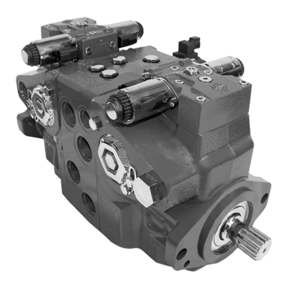
Axial piston single pumps size 147/165
Hide thumbs
Also See for H1:
- Technical information (144 pages) ,
- Service manual (72 pages) ,
- Basic information (40 pages)

Related Manuals for Danfoss H1


Summary of Contents for Danfoss H1
- Page 1 Technical Information H1 Axial Piston Single Pumps Size 147/165 powersolutions.danfoss.com...
- Page 2 Technical Information H1 Axial Piston Single Pumps, Size 147/165 Revision history Table of revisions Date Changed May 2017 NFPE gen. 3 changes. 0701 November 2015 Master Model Code changes. 0600 September 2014 MDC, CCO, and Swash Angle Sensor options added...
-
Page 3: Table Of Contents
Technical Information H1 Axial Piston Single Pumps, Size 147/165 Contents Technical specifications H1 Pump General Specification..............................5 H1P 147/165 Technical Data................................ 5 H1P 147/165 Operating Parameters ............................6 Fluid Specifications ..................................6 External Radial Shaft Loads................................7 H1P 147/165 Bearing Life................................7 H1P 147/165 Mounting Flange Loads ............................. 8 Charge Pump Selection..................................8... - Page 4 Contents H1P 147/165 Auxiliary mounting, option H2 (SAE A, 9 teeth)..................43 H1P 147/165 Auxiliary mounting, option H1 (SAE A, 11 teeth)..................44 H1P 147/165 Auxiliary mounting, option H3 (SAE B, 13 teeth)..................45 H1P 147/165 Auxiliary mounting, option H5 (SAE B-B, 15 teeth).................46 H1P 147/165 Auxiliary mounting, option H6 (SAE C, 14 teeth)..................47...
-
Page 5: Technical Specifications
Technical Information H1 Axial Piston Single Pumps, Size 147/165 Technical specifications H1 Pump General Specification Axial piston pump of cradle swashplate design with variable displacement Design Clockwise, Counterclockwise Direction of rotation Main pressure ports: ISO split flange boss Pipe connections... -
Page 6: H1P 147/165 Operating Parameters
Technical Information H1 Axial Piston Single Pumps, Size 147/165 Technical specifications H1P 147/165 Operating Parameters Feature Size 147/165 500 min (rpm) Input speed Minimum for internal and external charge supply. 1200 min (rpm) Minimum for full performance for internal charge supply. -
Page 7: External Radial Shaft Loads
= shaft moment L = flange distance = external force to the shaft Thrust loads should be avoided. Contact your Danfoss representative in the event thrust loads are anticipated. H1P 147/165 Bearing Life Maximum external shaft load based on shaft deflection... -
Page 8: H1P 147/165 Mounting Flange Loads
= 6500 N•m [57 500 lbf•in] Shock load moment = 16 300 N•m [ 144 000 lbf•in] For more information, see H1 Axial Piston Pumps, Basic Information, BC00000057, the section “Mounting flange loads”. Charge Pump Selection In most applications a general guideline is that the charge pump displacement should be at least 10% of the total displacement of all components in the system. - Page 9 Technical Information H1 Axial Piston Single Pumps, Size 147/165 Technical specifications Charge pump flow Charge pump power requirements 14.0 13.0 12.0 11.0 10.0 1500 2500 3500 1000 2000 3000 Speed min (rpm) 1500 2500 3500 P003 337E 1000 2000 3000...
-
Page 10: Master Model Code
Technical Information H1 Axial Piston Single Pumps, Size 147/165 Master Model Code Displacement 147.2 cm [8.98 in 165.1 cm [10.08 in A – Rotation Left hand (counter clockwise) Right hand (clockwise) B – Product version Revision code Z – Port configuration Inch, Customer O-ring port sealing according to ISO 11926-1 D –... - Page 11 Technical Information H1 Axial Piston Single Pumps, Size 147/165 Master Model Code D – Controls (continued) — Automotive Control (AC) Code AC type Voltage Speed Wire Angle DEUTSCH sensor harness sensor Connector AC–1 12 V — AC–1 24 V —...
- Page 12 Technical Information H1 Axial Piston Single Pumps, Size 147/165 Master Model Code F - Orifices Code Orifice Control Type Tank (A+B) A / B NFPE, AC – – – 0.8 mm – – – 1.3 mm – – 1.8 mm –...
- Page 13 Technical Information H1 Axial Piston Single Pumps, Size 147/165 Master Model Code G – Endcap options (Twin port, ISO 6162 split flange ports) Align with options T – Filtration (below) and K – Auxiliary mounting pads: • ISO 3019-1, flange 82–2 (SAE A, 9 and 11 teeth) •...
- Page 14 420 bar [6090 psi] 450 bar [6526 psi] L – with pressure limiter; K – without pressure limiter; F – setting for FDC. Please contact Danfoss Power Solutions for pressures not shown or for applied pressure above max. working pressure. 11063347 | BC00000061en-US0701 14 | ©...
- Page 15 Technical Information H1 Axial Piston Single Pumps, Size 147/165 Master Model Code S – Charge pump 26 cm³/rev [1.69 in³/rev] 34 cm³/rev [2.07 in³/rev] No charge pump, external charge supply (Align with options: E and T) T – Filtration (Align with option G – Endcap selection)
- Page 16 Technical Information H1 Axial Piston Single Pumps, Size 147/165 Master Model Code Y – Special settings (SIL–2 non-certifiable, without customer files) Code CAN J1939 ECO fuel saving Functional Cruise control Control AC type mode option in/out – (12 V in/out –...
-
Page 17: Control Options
Technical Information H1 Axial Piston Single Pumps, Size 147/165 Control Options Electrical Displacement Control (EDC) The Electrical Displacement Control (EDC) consists of a pair of proportional solenoids on each side of a three-position, four-way porting spool. The proportional solenoid applies a force input to the spool, which ports hydraulic pressure to either side of a double acting servo piston. -
Page 18: Edc Solenoid Data
For coil location see Installation drawings. Control Response H1 controls are available with optional control passage orifices to assist in matching the rate of swashplate response to the application requirements (e.g. in the event of electrical failure). The time required for the pump output flow to change from zero to full flow (acceleration) or full flow to zero (deceleration) is a net function of spool porting, orifices, and charge pressure. -
Page 19: Edc Response Time
Technical Information H1 Axial Piston Single Pumps, Size 147/165 Control Options Typical response times at the following conditions: 250 bar [3626 psi] ∆p 30 mm²/s [141 SUS] and 50 °C [122 °F] Viscosity and temperature 20 bar [290 psi] Charge pressure... -
Page 20: Manual Displacement Control (Mdc)
Technical Information H1 Axial Piston Single Pumps, Size 147/165 Control Options Manual Displacement Control (MDC) A Manual proportional Displacement Control (MDC) consists of a handle on top of a rotary input shaft. The shaft provides an eccentric connection to a feedback link. This link is connected on its one end with a porting spool. -
Page 21: Mdc General Information
As seen from shaft side. Control Response H1 controls are available with optional control passage orifices to assist in matching the rate of swashplate response to the application requirements (e.g. in the event of electrical failure). The time required for the pump output flow to change from zero to full flow (acceleration) or full flow to zero (deceleration) is a net function of spool porting, orifices, and charge pressure. -
Page 22: Mdc Response Time
H1 Axial Piston Single Pumps, Size 147/165 Control Options H1 pumps are limited in mechanical orificing combinations. Mechanical servo orifices are to be used only for fail-safe return to neutral in the event of an electrical failure. Typical response times at the following conditions: 250 bar [3626 psi] ∆p... -
Page 23: Case Gauge Port M14
Technical Information H1 Axial Piston Single Pumps, Size 147/165 Control Options Case Gauge Port M14 The drain port should be used when the control is mounted on the unit’s bottom side to flush residual contamination out of the control. MDC schematic diagram... -
Page 24: Forward-Neutral-Reverse Electric Control (Fnr), Options: A9 (12 V) And B1 (24 V)
Technical Information H1 Axial Piston Single Pumps, Size 147/165 Control Options Forward-Neutral-Reverse electric control (FNR), options: A9 (12 V) and B1 (24 V) The 3-position FNR control uses an electric input signal to switch the pump to a full stroke position. -
Page 25: Control Response
50. Control Response H1 controls are available with optional control passage orifices to assist in matching the rate of swashplate response to the application requirements (e.g. in the event of electrical failure). The time required for the pump output flow to change from zero to full flow (acceleration) or full flow to zero (deceleration) is a net function of spool porting, orifices, and charge pressure. -
Page 26: Non Feedback Proportional Electric Control (Nfpe)
Technical Information H1 Axial Piston Single Pumps, Size 147/165 Control Options Non Feedback Proportional Electric Control (NFPE) The Non Feedback Proportional Electric (NFPE) control is an electrical automotive control in which an electrical input signal activates one of two proportional solenoids that port charge pressure to either side of the pump servo cylinder. - Page 27 Technical Information H1 Axial Piston Single Pumps, Size 147/165 Control Options Pump displacement vs. input signal 100 % NFPE control Signal Current mA(DC) "0" 100 % P003 187E 11063347 | BC00000061en-US0701 | 27 © Danfoss | May 2017...
-
Page 28: Nfpe Control Signal Requirements
Technical Information H1 Axial Piston Single Pumps, Size 147/165 Control Options NFPE Control Signal Requirements Control current Voltage Pin connections 12 V 666 mA 1168 mA 1540 mA any order 24 V 320 mA 600 mA 770 mA Factory test current, for vehicle movement or application actuation expect higher or lower value. -
Page 29: Control Response
Control Options Control Response H1 controls are available with optional control passage orifices to assist in matching the rate of swashplate response to the application requirements (e.g. in the event of electrical failure). The time required for the pump output flow to change from zero to full flow (acceleration) or full flow to zero (deceleration) is a net function of spool porting, orifices, and charge pressure. -
Page 30: Automotive Control (Ac)
Control Options Automotive Control (AC) The H1 Automotive Control (AC) is an electric NFPE Control with an integrated microcontroller, installed on the pump. The integrated microcontroller enhanced control performance with a flexible, configurable control scheme for an entire single path propel transmission. It can be used in combination with fixed and variable displacement hydraulic-motors. -
Page 31: Performance Functions
Factory calibration for hysteresis compensation. • Starting current adjustment in the factory • Pre-installed application software and parameter files For more information, see Automotive Control for H1 SIngle Pumps Technical Information, BC00000213. 11063347 | BC00000061en-US0701 | 31 © Danfoss | May 2017... -
Page 32: Fan Drive Control (Fdc)
P301 442 H1 pumps with FDC will be delivered from factory with nominal PL setting of 150 bar [2175 psi]. The PL must be re-adjusted to ensure that the fan reaches the desired fan speed to satisfy the cooling needs of the system. -
Page 33: Control Response
P301 443 Control Response H1 controls are available with optional control passage orifices to assist in matching the rate of swashplate response to the application requirements (e.g. in the event of electrical failure). The time required for the pump output flow to change from zero to full flow (acceleration) or full flow to zero (deceleration) is a net function of spool porting, orifices, and charge pressure. -
Page 34: Manual Override (Mor)
Technical Information H1 Axial Piston Single Pumps, Size 147/165 Control Options Manual Over Ride (MOR) All controls are available with a Manual Over Ride (MOR) either standard or as an option for temporary actuation of the control to aid in diagnostics. -
Page 35: Swash Plate Angle Sensor For Nfpe And Ac2 Controls
Technical Information H1 Axial Piston Single Pumps, Size 147/165 Control Options Swash plate angle sensor for NFPE and AC2 controls The angle sensor detects the swash plate angle position and direction of rotation from the zero position. The swash angle sensor works on the AMR sensing technology. Under the saturated magnetic field, the resistance of the element varies with the magnetic field direction. -
Page 36: Swash Plate Angle Sensor Connector
Technical Information H1 Axial Piston Single Pumps, Size 147/165 Control Options Swash plate angle sensor connector Pin assignment 1. Ground (GND) 2. Output Signal 2 (SIG2) – Secondary (redundant) 3. Output Signal 1 (SIG1) – Primary (nominal) 4. Supply (V+) -
Page 37: Control-Cut-Off Valve (Cco Valve)
Control Options Control-Cut-Off valve (CCO valve) The H1 pump offers an optional control cut off valve integrated into the control. This valve will block charge pressure to the control, allowing the servo springs to de-stroke both pumps regardless of the pump´s primary control input. -
Page 38: Cco Solenoid Data
Technical Information H1 Axial Piston Single Pumps, Size 147/165 Control Options CCO solenoid data Nominal supply voltage 12 V 24 V 14.6 V 29 V Supply voltage Maximum 9.5 V 19 V Minimum 10.7 Ω 41.7 Ω Nominal coil resistance at 20°C... -
Page 39: Displacement Limiter
Control Options Displacement limiter H1 pumps are designed with optional mechanical displacement (stroke) limiters factory set to max. displacement. The maximum displacement of the pump can be set independently for forward and reverse using the two adjustment screws to mechanically limit the travel of the servo piston down to 50 % displacement. -
Page 40: Dimensions
Torque rating Rated 3000 N•m [26 550 lbf•in] Maximum For definitions of maximum and rated torque values, refer to H1 Axial Piston Pumps Basic Information, BC00000057, the section “Shaft Torque Ratings and Spline Lubrication”. 11063347 | BC00000061en-US0701 40 | ©... -
Page 41: H1P Input Shaft - Option G3 (Sae D, 13 Teeth)
Torque rating Rated 2206 N•m [19 500 lbf•in] Maximum For definitions of maximum and rated torque values, refer to H1 Axial Piston Pumps Basic Information, BC00000057, the section “Shaft Torque Ratings and Spline Lubrication”. 11063347 | BC00000061en-US0701 | 41 ©... -
Page 42: H1P Input Shaft - Option F3, Code 44-3
The Danfoss H1 tapered shaft has been designed using the industry standard ISO 3019-1, minus the through-hole in the end of the shaft. Danfoss recommends a self-locking nut instead of a castle nut and pin. The nut and mating square-cut key are customer supplied. The specified torque rating of the tapered shaft is based on the cross-sectional diameter of the shaft, through the keyway, and assumes the proper clamp and fit between shaft and coupling. -
Page 43: H1P 147/165 Auxiliary Mounting, Option H2 (Sae A, 9 Teeth)
Spline 162 N•m [1430 lbf•in] Maximum torque For definitions of maximum and rated torque values, refer to H1 Axial Piston Pumps Basic Information, BC00000057, the section “Shaft Torque Ratings and Spline Lubrication”. Caution Standard pad cover is installed only to retain coupling during shipping. Do not operate pump without an auxiliary pump or running cover installed. -
Page 44: H1P 147/165 Auxiliary Mounting, Option H1 (Sae A, 11 Teeth)
Spline 296 N•m [2620 lbf•in] Maximum torque For definitions of maximum and rated torque values, refer to H1 Axial Piston Pumps Basic Information, BC00000057, the section “Shaft Torque Ratings and Spline Lubrication”. Caution Standard pad cover is installed only to retain coupling during shipping. Do not operate pump without an auxiliary pump or running cover installed. -
Page 45: H1P 147/165 Auxiliary Mounting, Option H3 (Sae B, 13 Teeth)
Spline 395 N•m [3500 lbf•in] Maximum torque For definitions of maximum and rated torque values, refer to H1 Axial Piston Pumps Basic Information, BC00000057, the section “Shaft Torque Ratings and Spline Lubrication”. Caution Standard pad cover is installed only to retain coupling during shipping. Do not operate pump without an auxiliary pump or running cover installed. -
Page 46: H1P 147/165 Auxiliary Mounting, Option H5 (Sae B-B, 15 Teeth)
Spline 693 N•m [6130 lbf•in] Maximum torque For definitions of maximum and rated torque values, refer to H1 Axial Piston Pumps Basic Information, BC00000057, the section “Shaft Torque Ratings and Spline Lubrication”. Caution Standard pad cover is installed only to retain coupling during shipping. Do not operate pump without an auxiliary pump or running cover installed. -
Page 47: H1P 147/165 Auxiliary Mounting, Option H6 (Sae C, 14 Teeth)
Spline 816 N•m [7220 lbf•in] Maximum torque For definitions of maximum and rated torque values, refer to H1 Axial Piston Pumps Basic Information, BC00000057, the section “Shaft Torque Ratings and Spline Lubrication”. Caution Standard pad cover is installed only to retain coupling during shipping. Do not operate pump without an auxiliary pump or running cover installed. -
Page 48: H1P 147/165 Auxiliary Mounting, Option H4 (Sae D, 13 Teeth)
Spline 2206 N•m [19 525 lbf•in] Maximum torque For definitions of maximum and rated torque values, refer to H1 Axial Piston Pumps Basic Information, BC00000057, the section “Shaft Torque Ratings and Spline Lubrication”. Caution Standard pad cover is installed only to retain coupling during shipping. Do not operate pump without an auxiliary pump or running cover installed. -
Page 49: H1P 147/165 Displacement Limiter, Option B
Technical Information H1 Axial Piston Single Pumps, Size 147/165 Dimensions H1P 147/165 displacement limiter, option B 176.5 ± 2.0 176.5 ± 2.0 153.7 ± 1.0 [6.949 ± 0.079] [6.949 ± 0.079] [6.051 ± 0.039] 2 x Wrench size 6 (external hex) -
Page 50: Installation Drawings
Technical Information H1 Axial Piston Single Pumps, Size 147/165 Installation drawings Port Description H1P 147/165 P005 932 Ports per ISO 11926-1 description Port Description Size 147/165 System ports A and B Ø31.5 mm; M12 x 1.75; 20 min. full thread depth;... - Page 51 Technical Information H1 Axial Piston Single Pumps, Size 147/165 Installation drawings P005 933 1. Charge pressure construction port ∕ –24 2. Connector DEUTSCH DT04-2P, to be paint free Ports per ISO 11926-1 description Port Description Size 147/165 Charge filtration port from/to filter ∕...
-
Page 52: Dimensions H1P 147/165
Technical Information H1 Axial Piston Single Pumps, Size 147/165 Installation drawings Dimensions H1P 147/165 333.0 ± 0.4 Mounting Flange surface [13.112 ± 0.079] Servo Gauge Port “M4” flange 127 - 4 per ISO 3019-1 255.7 + 0.6 Port ISO 11926-1 to be paint free –... - Page 53 Technical Information H1 Axial Piston Single Pumps, Size 147/165 Installation drawings 179.9 ±1.0 [7.08 ±0.039] Servo gauge port “M5” 150.0 ±1.0 [5.91 ±0.039] Port ISO 11926-1 – 152.6 ±1.0 131.9 ±1.0 ∅24.5 max clearance dia for fitting Connector: [6.01 ±0.039] [5.19 ±0.039]...
- Page 54 Technical Information H1 Axial Piston Single Pumps, Size 147/165 Installation drawings System A gauge port “MA” Port ISO 11926-1 – ∅28 max clearance dia for fitting 255.7 [10.07] Rotation Rotation (4x) ∅40 ± 0.25 (4x) ∅20.6 + 0.25 (4x) 80.8 ± 0.25 [1.575 ±...
-
Page 55: Controls
Technical Information H1 Axial Piston Single Pumps, Size 147/165 Controls Electric Displacement Control (EDC), option A2 (12 V) / A3 (24 V) Connector : Deutsch DT04-2P to be paint free Case gauge port “M14” Port ISO 11926-1 – ∅21 max clearance dia for fitting Shaft L 109.9 ±... -
Page 56: H1P 147/165 Manual Displacement Control (Mdc), Option M1
Technical Information H1 Axial Piston Single Pumps, Size 147/165 Controls H1P 147/165 Manual Displacement Control (MDC), option M1 Case gauge port M14 ISO 11926-1 -7/16-20 4x M6x1-6H thd. 9 min. full thd. depth paint free Control handle shaft Shaft 61.4±0.8 Mounting flange 79.2±0.8... -
Page 57: H1P 147/165 Manual Displacement Control (Mdc) With Nss, Option M2
Technical Information H1 Axial Piston Single Pumps, Size 147/165 Controls H1P 147/165 Manual Displacement Control (MDC) with NSS, option M2 Case gauge port M14 ISO 11926-1 -7/16-20 4x M6x1-6H thd. 9 min. full thd. depth Control handle shaft paint free Shaft 61.4±0.8... -
Page 58: H1P 147/165 Manual Displacement Control (Mdc) With Cco, Option M3, M4
Technical Information H1 Axial Piston Single Pumps, Size 147/165 Controls H1P 147/165 Manual Displacement Control (MDC) with CCO, option M3, M4 Shaft Brake gauge port X7 ISO 11926-1 -7/16-20 140.4 ±1.2 Case gauge port M14 ISO 11926-1 -7/16-20 4x M6x1-6H thd. -
Page 59: H1P 147/165 Manual Displacement Control (Mdc) With Nss And Cco, Option M5, M6
Technical Information H1 Axial Piston Single Pumps, Size 147/165 Controls H1P 147/165 Manual Displacement Control (MDC) with NSS and CCO, option M5, M6 Shaft Brake gauge port X7 140.4 ±1.2 ISO 11926-1 -7/16-20 Case gauge port M14 ISO 11926-1 -7/16-20 4x M6x1-6H thd. -
Page 60: Automotive Control (Ac) Dimensions
Technical Information H1 Axial Piston Single Pumps, Size 147/165 Controls Automotive Control (AC) Dimensions 220 ±2.5 110 ±1.5 61.2 ±0.8 61.2 ±0.8 30.2 ±0.8 CCC3 P005 930 1. Mounting flange 2. Shaft 3. Plug removing can cause contamination issues 4. PPU wire harness is factory installed to speed sensor... -
Page 61: Forward-Neutral-Reverse (Fnr) With Manual Override, Options A9 (12 V) / B1 (24 V)
Technical Information H1 Axial Piston Single Pumps, Size 147/165 Controls Forward-Neutral-Reverse (FNR) with manual override, options A9 (12 V) / B1 (24 V) Connector : Deutsch DT04-2P to be paint free Case gauge port “M14” Port ISO 11926-1 – ∅21 max clearance dia for fitting Shaft L 79.4 ±... -
Page 62: Filtration
Technical Information H1 Axial Piston Single Pumps, Size 147/165 Filtration Suction filtration, option L, H1P 147/165 255.7 + 0.6 – 0.5 [10.068 + 0.024 – 0.02 Charge pump inlet “S” Port ISO 11926-1 – 1 115.8 ± 0.2 [4.56 ± 0.01]... -
Page 63: Integral Full Flow Charge Pressure Filtration With Filter Bypass Sensor, Option M, H1P 147/165
Technical Information H1 Axial Piston Single Pumps, Size 147/165 Filtration Integral full flow charge pressure filtration with filter bypass sensor, option M, H1P 147/165 Connector : Deutsch DTM04-2P to be paint free 32.7 ± 1.0 Charge gauge port “M6” [1.288 ± 0.039] 314.91 ±... - Page 64 Phone: +86 21 3418 5200 Danfoss can accept no responsibility for possible errors in catalogues, brochures and other printed material. Danfoss reserves the right to alter its products without notice. This also applies to products already on order provided that such alterations can be made without changes being necessary in specifications already agreed.
Need help?
Do you have a question about the H1 and is the answer not in the manual?
Questions and answers