Sign In
Upload
Manuals
Brands
Canon Manuals
Copier
3225
Canon 3225 Manuals
Manuals and User Guides for Canon 3225. We have
7
Canon 3225 manuals available for free PDF download: Service Manual, Troubleshooting Manual, Getting Started Manual, Easy Operation Manual, Manual, Media Manual
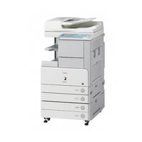
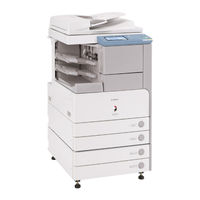
Canon 3225 Service Manual (746 pages)
Brand:
Canon
| Category:
Copier
| Size: 30.43 MB
Table of Contents
Table of Contents
7
Table of Contents
13
Chapter 1 Introduction
25
System Construction
29
System Configuration of Original Feeding Options
29
System Configuration of Pickup/Delivery Options
30
System Configuration of Print/Send Options
32
Functions of Print/Send Options
34
Product Specifications
35
Names of Parts
35
External View
35
Cross-Section
36
Using the Machine
37
Turning on the Power Switch
37
When Turning off the Main Power Switch
37
Control Panel
39
User Mode Items
40
Overview
40
Common Settings
40
Timer Settings
41
Adjustment/Cleaning
41
Report Settings
42
System Settings
42
Copy Settings
44
Communications Settings*2
45
Mail Box Settings
46
Address Book Settings*5
46
Maintenance by the User
47
Routine Cleaning
47
Inspection
50
Safety
51
Points to Note at Disassembly/Assembly
51
Safety of the Laser Light
51
CDRH Regulations
51
Handling the Laser Unit
51
Safety of Toner
52
Notes When Handling a Lithium Battery
53
Product Specifications
53
Methods/Functions
53
Function List
54
Printing Speed
54
Paper Type
56
Chapter 2 Installation
65
Table of Contents
67
Making Pre-Checks
69
Checking Installation Environment
69
Points to Note before Installation
70
Combination Table of Accessories
70
Checking the Contents
71
Unpacking and Installation
73
Unpacking and Removing Fixing Member
73
Installing the Filter
74
Installing Toner Container
75
Installing Drum Unit
76
Installing Other Parts
79
Fixing the Host Machine
81
Connecting the Cable
81
Points to Note When Turning off the Main Power
82
Stirring Toner
82
Cassette Setting
82
APVC Correction of Drum
82
Auto Gradation Correction
82
Screen Position Adjustment
83
Checking the Connection to the Network
85
Overview
85
Ping Operation Procedure
85
Checking Network with Remote Host Address
85
When Not Using Network Connection
85
Checking the Images/Operations
85
Checking the Image/Operation
85
Troubleshooting the Network
85
Check with Loopback Address
85
Check with Local Host Address
85
Installing the Card Reader
86
Installation Procedure
86
Installation Procedure in the Imageware Accounting Manager (Hereinafter Referred to Iwam) Environment
89
Installing the Original Holder
89
Checking Components
89
Installation Procedure
89
Checking Parts to Install
90
Turning off the Power of the Host Machine
91
Installation Procedure
91
Installing the Reader Heater
90
Installing the Cassette Heater
94
Checking Parts to Install
94
Turning off the Power of the Host Machine
94
Installation Procedure (Cassette Heater Unit)
94
Checking Parts to Install
98
Installation Procedure (Cassette Heater Attachment)
99
Installing the Deck Heater
103
Checking the Parts to Install
103
Turning off the Power of the Host Machine
103
Installation Procedure
103
Installing the Memory
106
Checking the Contents
106
Turning off the Power of the Host Machine
106
Installation Procedure
106
Installing the Memory (System Upgrade Memory)
106
Installing the Expansion Bus Kit
107
Checking the Contents
107
Turning off the Power of the Host Machine
107
Installation Procedure
107
Installing the Voice Guidance Kit
108
Notice at Installation
108
Checking the Contents
108
Turning off the Power of the Host Machine
108
Installation Procedure
108
Checking the Settings
111
Operation Check
111
Installing the Voice Operation Kit
111
Notice at Installation
111
Checking the Contents
111
Turning off the Power of the Host Machine
112
Installation Procedure
112
Checking the Settings
116
Operation Check
116
Installing the Wireless Network Interface Adapter
116
Notice at Installation
116
Checking the Contents
116
Turning off the Power of the Host Machine
116
Installation Procedure
117
Attaching the Label
118
Installing the Ipsec Board
118
Notice at Installation
118
Checking the Contents
118
Turning off the Power of the Host Machine
118
Installation Procedure
118
Functional Construction
125
Connecting the Main Pcbs
126
Basic Sequence of Operation at Power-On
127
Table of Contents
131
Construction
133
Construction and Mechanisms
133
Construction of the Electrical Circuitry
135
Hdd
137
Overview
138
Chapter 3 Basic Operation
138
Chapter 4 Main Controller
138
Start-Up Sequence
138
Overview
139
Shut-Down Sequence
139
Flow of Operation
139
Image Processing
140
Construction of the Image Processing Module
140
Reader Unit Input Image Processing
140
Compression/Extension/Editing Block
141
Printer Unit Output Image Processing
141
Flow of Image Data
142
Flow of Image Data According to Copy Functions
142
Flow of Image Data for the Box Function
142
Main Controller PCB
142
Flow of Image Data for the SEND Function
143
Flow of Image Data for the Fax Reception Function
144
Parts Replacement Procedure
145
Removing the Main Controller PCB
146
Sdram
146
Removing the SDRAM (for Image Processing)
146
Hdd
147
Removing the Sdram (for System Processing)
147
Removing the Hdd
147
Removing the Wireless Lan Pcb
147
Removing the Wireless LAN PCB
148
Ipsec PCB
148
Removing the Ipsec PCB
148
Wireless Lan Pcb
147
PCI Bus Expansion PCB
149
Removing the PCI Bus Expansion PCB
150
Voice Operation PCB
150
Removing the Voice Operation PCB
150
FAX Expansion PCB
151
Removing the FAX Expansion PCB
151
Table of Contents
155
Construction
157
Specifications/Controls/Functions
157
Major Components
158
Configuration of Control System
159
Reader Controller PCB
160
Basic Sequence
161
Basic Sequence at Power-On
161
Basic Sequence at Start Key on (Book Mode/1 Original)
161
Basic Sequence at Start Key on (ADF Mode/1 Original)
161
Various Control
162
Controlling the Scanner Drive System
162
Overview
162
Scanner Motor Control
162
CCD
164
Overview
164
Enlargement/Reduction
167
Chapter 5 Original Exposure System
167
Magnification in Sub Scanning Direction
167
Magnifications in Main Scanning Direction
167
Detecting the Size of Originals
168
Overview
168
Control Details
168
Detection Operation Overview
170
Dirt Sensor Control
171
Overview
171
White Board Dust Detection Control
173
Image Processing
174
Overview
174
CCD Drive
174
Gain Correction and Offset Correction of CCD Output
174
A/D Conversion of CCD Output
175
Shading Correction (Overview)
175
Shading Adjustment
175
Shading Correction
175
Parts Replacement Procedure
176
CCD Unit
176
Removing the CCD Unit
176
When Replacing the CCD Unit
177
CCD Cover Unit
177
Removing the CCD Cover Unit
177
Copyboard Glass
177
Removing the Copyboard Glass
177
When Replacing the Copyboard Glass
178
Removing the ADF Reading Glass
179
When Replacing the ADF Reading Glass
179
Reader Controller PCB
180
Points to Note before Replacing the Reader Controller PCB
180
Removing the Reader Controller PCB
180
After Replacing the Reader Controller PCB
180
LED Driver PCB
181
Removing the LED Driver PCB
181
Scanner Motor
181
Removing the Scanner Motor
181
Copyboard Cover Open/Close Sensor
181
Removing the Copyboard Cover Open/Closed Sensor (Front/Rear)
181
CCD HP Sensor
182
Removing the CCD Unit HP Sensor
182
Original Size Sensor
182
Removing the Original Size Sensor
182
Reader Heater (Option)
183
Removing the Reader Heater (Right)
183
Removing the Reader Heater (Left)
183
Table of Contents
187
Construction
189
Specifications/Controls/Functions
189
Main Configuration Parts
189
Chapter 6 Laser Exposure
190
Control System Configuration
190
Basic Sequence
191
Various Controls
192
Controlling the Laser Activation Timing
192
Laser ON/OFF Control
192
Main Scanning Synchronous Control
193
Controlling the Intensity of Laser Light
193
APC Control
193
Controlling the Laser Scanner Motor
194
Laser Scanner Motor Control
194
Controlling the Laser Shutter
195
Laser Shutter Control
195
Parts Replacement Procedure
196
Laser Scanner Unit
196
Before Removing the Laser Unit
196
Removing the Laser Unit
196
After Replacing the Laser Scanner Unit
196
Table of Contents
199
Construction
201
Specifications of the Image Formation System
201
Major Components of the Image Formation System
202
Image Formation Process
203
Image Formation Process (Outline)
203
Image Formation Process (Image Formation)
204
Basic Sequence
205
Chapter 7 Image Formation
205
Sequence of Operation (Copying)
205
Sequence of Operation (Last Rotation)
206
Image Stabilization Control
207
Overview
207
APVC Control
207
ATVC Control
207
PASCAL Control (Image Gradation)
208
Drum Unit
209
Outline of the Drum Unit
209
Configuration
209
Charging Mechanism
210
Controlling the Primary Charging Bias
210
Primary Charging Roller Cleaning Mechanism
210
Drum Cleaner Unit
210
Photosensitive Drum Cleaning
210
Developing Unit
211
Configuration
211
Controlling the Developing Bias
211
Toner Container
212
Configuration
212
Route of Toner Supply
213
Controlling the Drive of the Toner Cartridge
213
Toner Supply Control
214
Recovery Sequence
214
Toner Level Detection
214
Transfer Unit
215
Outline of the Transfer Unit
215
Outline
215
Controlling the Transfer Bias
215
Transfer Roller Bias Control
215
Cleaning
215
Transfer Roller Cleaning Mechanism
215
Separation Mechanism
215
Controlling the Static Eliminator Bias
215
Transfer Mechanism
216
Transfer Guide Bias
216
Transfer Guide Bias Control
216
Photosensitive Drum Cleaning
217
Outline
217
Collection of Waste Toner
217
Checking the Waste Toner Box
217
Drum Unit
218
Before Removing the Drum Unit
218
Removing the Drum Unit
218
After Replacing Drum Unit
219
Parts Replacement Procedure
218
Pre-Exposure Lamp
218
Before Removing the Pre-Exposure Lamp
218
Removing the Pre-Exposure Lamp
218
Hopper Assembly
219
Before Removing the Hopper Unit
219
Removing the Hopper Unit
219
Sub Hopper
220
Before Removing the Sub Hopper
220
Removing the Sub Hopper
220
Developing Assembly
221
Before Removing the Developing Assembly
221
Removing the Developing Assembly
221
After Replacing Developing Assembly/Developing Cylinder
222
Developing Cylinder
222
Before Removing the Developing Cylinder
222
Removing the Developing Cylinder
222
After Replacing Developing Assembly/Developing Cylinder
223
Transfer Charging Roller
224
Removing the Transfer Roller
224
Waste Toner Box
224
Removing the Waste Toner Container
224
Toner Level Sensor
225
Before Removing the Toner Level Sensor
225
Removing the Toner Feed Screw Motor
225
Before Removing the Toner Feed Screw Motor
225
Static Charge Eliminator
226
Removing the Static Eliminator
226
Table of Contents
229
Construction
233
Specifications, Controls, and Functions
233
Division into Blocks
234
Chapter 8 Pickup/Feeding System
235
Arrangement of Rollers
235
Diagram of Paper Paths (W/ 3 Way Unit-A1/ Copy Tray)
236
Diagram of Paper Paths (W/ Inbody Finisher/ Copy Tray)
237
Diagram of Paper Paths (W/ Finisher/Saddle Finisher)
238
Arrangement of Sensors
239
Route of Drive
240
Basic Sequence
242
Acceleration Intervals
242
Detecting Jams
246
Delay Jams
246
Delay Jam Outside the Cassette Pickup Assembly
246
Delay Jam in the Cassette Pickup Assembly
246
Stationary Jams
247
Common Stationary Jam
247
Stationary Jam at Power-On
247
Other Jams
247
Door Open Jam
247
Paper Size Mismatch JAM
248
Error Retry JAM
248
Cassette Pick-Up Unit
249
Overview
249
Basic Sequence
249
Identifying the Paper Size
250
Setting up the Universal Cassette
251
Paper Level Sensor
252
Manual Feed Pickup Unit
254
Overview
254
Basic Sequence of Operation
254
Identifying the Paper Size
255
Paper Retaining Mechanism
256
Registration Unit
257
Overview
257
Checking Horizontal Registration
257
Duplex Feeding Unit
258
Overview
258
Sequence of Image Formation
259
Flow of Paper
260
Parts Replacement Procedure
262
Sensor Mount
263
Cassette Pick-Up Motor 1
264
Cassette Pick-Up Motor 2
265
Cassette Paper Level Sensor (A/B)
266
Before Removing the Cassette Paper Level Sensor (A/B)
266
Removing the Cassette Paper Level Sensor (A/B)
266
Cassette Paper Sensor
266
Before Removing the Cassette Paper Sensor
266
Removing the Cassette Paper Sensor
266
Cassette Retry Paper Sensor
266
Before Removing the Cassette Retry Paper Sensor
266
Removing the Cassette Retry Paper Sensor
266
Slide Resistor
266
Removing the Slide Resistor
267
Cassette Pickup Solenoid
267
Before Removing the Cassette Pickup Solenoid
267
Removing the Cassette Pickup Solenoid
267
Manual Tray Assembly
267
Before Removing the Manual Feed Tray Unit
267
Removing the Manual Feed Tray Unit
267
When Replacing the Manual Feed Tray
268
Manual Feed Unit
268
Before Removing the Manual Feed Unit
268
Removing the Manual Feed Unit
268
Manual Pickup Roller
268
Before Removing the Manual Feed Pickup Roller
268
Removing the Manual Feed Pickup Roller
268
Manual Feeder Pad Up/Down Solenoid
269
Before Removing the Manual Feeder Pad Up/Down Solenoid
269
Removing the Manual Feeder Pad Up/Down Solenoid (Ir 3425/3235/3230)
269
Removing the Manual Feeder Pad Up/Down Solenoid (Ir 3225)
271
Manual Pick-Up Clutch
272
Before Removing the Manual Feed Pickup Clutch (Ir 3245/3235/3230)
272
Removing the Manual Feed Pickup Clutch (Ir 3245/3235/3230)
272
Before Removing the Manual Feed Pickup Clutch (Ir 3225)
272
Removing the Manual Feed Pickup Clutch (Ir 3225)
272
Manual Separation Pad
273
Before Removing the Manual Feed Separation Pad
273
Removing the Manual Feed Separation Pad
273
Registration Clutch
273
Before Removing the Registration Clutch
273
Removing the Registration Clutch
273
Way Unit
273
Before Removing the 3 Way Unit
273
Removing the 3 Way Unit
273
Feeding Roller
274
Vertical Path Roller
274
Duplex Feed Roller 2
275
Duplex Feed Sensor
276
Fixing/ Delivery Drive Assembly
277
Table of Contents
281
Construction
283
Major Components
283
Specifications, Control Mechanisms, and Functions
283
Basic Sequence
284
Power-On Sequence
284
Down Sequence
284
Various Control Mechanisms
285
Controlling the Speed of the Fixing Film
285
Controlling the Fixing Film Speed in Response to Low Temperature
285
Controlling the Fixing Film Speed
285
Controlling the Fixing Film Temperature
285
Controlling the Power Supply in Response to Low Temperature
285
Controlling the Feeding in Response to Low Temperature
285
Controlling the Power Supply at Start-Up
286
Copying Temperature Control
286
Changing the Fixing Film Control Temperature
286
Temperature Control in Response to Automatic Double-Sided Copy
286
Temperature Control in Response to Change of Paper Size
286
Fixing Film Cleaning
287
Detecting the Passage of Paper
287
Protective Functions
288
Detecting an Error
289
Parts Replacement Procedure
290
Fixing Unit
290
Before Removing the Fixing Unit
290
Removing the Fixing Unit
290
Pressure Roller
290
Before Removing the Pressure Roller
290
Removing the Pressure Roller
290
Cleaning Roller
291
Before Removing the Cleaning Roller
291
Removing the Cleaning Roller
291
Fixing Film
292
Before Removing the Fixing Film Unit
292
Removing the Fixing Film Unit
292
Internal Delivery Sensor
294
Before Removing the Internal Delivery Sensor
294
Removing the Internal Delivery Sensor
294
Fixing Film Sensor
295
Before Removing the Fixing Film Sensor
295
Removing the Fixing Film Sensor
295
Fixing Inlet Guide
296
Before Removing the Fixing Inlet Guide
296
Removing the Fixing Inlet Guide
296
Table of Contents
299
Control Panel
303
LCD Indication Processing
303
Adjusting the LCD Contrast
303
Adjusting Fax Sound Volume
303
Functions of the Control Panel CPU
304
Chapter 10 External and Controls
305
Counters
305
Timing of Increasing the Count
305
Fans
306
Speed Control
307
Operation Sequence
307
Power Supply System
308
Power Supply
308
Power Supply Route Inside the Printer
308
Power Supply Route in the Reader Unit
310
Timing of Supply to the Reader Unit
310
Connection to Options
311
Heater Operating Condition
311
Rated Output of the DC Power Supply PCB
311
Rated Output of the 24V Power Supply PCB
311
Rated Output of the 12V Power Supply PCB
312
Rated Output of the Option Power Supply PCB
312
Rated Output of the All-Night Power Supply PCB
312
Protection Function
312
Protective Functions
312
Backup Battery
312
Energy-Saving Function
313
Power Supply State
313
SNMP Settings
314
Parts Replacement Procedure
316
External Covers
316
Delivery Tray
316
Removing the Delivery Tray
316
Delivery Tray Right Cover
316
Before Removing the Delivery Tray Right Cover
316
Removing the Delivery Tray Right Cover
316
Delivery Tray Rear Cover
316
Before Removing the Delivery Tray Rear Cover
316
Removing the Delivery Tray Rear Cover
316
Support Cover
317
Before Removing the Support Cover
317
Removing the Support Cover
317
Support Cover (Right)
317
Before Removing the Support Right Cover
317
Removing the Support Right Cover
317
Right Cover (Lower Front)
318
Right Cover (Rear)
318
Removing the Rear Right Cover
318
Before Removing the Inside Right Cover
318
Removing the Inside Right Cover
318
Inside Bottom Cover
318
Before Removing the Inside Base Cover
318
Removing the Inside Base Cover
318
Removing the Front Cover Unit
319
Rear Cover (Upper)
319
Removing the Upper Rear Cover
319
Rear Cover (Lower)
319
Removing the Lower Rear Cover
319
Left Cover
319
Removing the Left Cover
319
Left Cover (Lower)
320
Removing the Lower Left Cover
320
Left Cover (Rear)
320
Before Removing the Rear Left Cover
320
Removing the Rear Left Cover
320
Delivery Cover
320
Removing the Delivery Cover
320
Toner Supply Cover
320
Removing the Toner Container Cover
320
Reader Left Cover
321
FAX Unit Cover
322
Removing the FAX Unit Cover
322
Control Panel Inside Frame
322
Before Removing the Control Panel Inside Frame
322
Removing the Control Panel Inside Frame
322
Control Panel Lower Cover
323
Removing the Control Panel Lower Cover
323
Main Drive Assembly
323
Before Removing the Main Drive Unit
323
Removing the Main Drive Unit (Ir 3245/3235/3230)
323
Removing the Main Drive Unit (Ir 3225)
324
Power Supply Unit
326
Before Removing the 12V Power Supply PCB
326
Removing the 12V Power Supply PCB
326
Before Removing the 24V Power Supply PCB
327
Control Panel LCD Unit
328
Before Removing the Control Panel LCD
328
Removing the Control Panel LCD
329
DC Controller PCB
329
Removing the DC Controller PCB
329
When Replacing DC Controller PCB
329
Control Panel Inverter PCB
330
Before Removing the Control Panel Inverter PCB
330
Removing the Control Panel Inverter PCB
330
Control Panel Key Switch PCB
330
Before Removing the Control Panel KEY PCB
330
Removing the Control Panel KEY PCB
330
Control Panel CPU PCB
330
Before Removing the Control Panel CPU PCB
330
Removing the Control Panel CPU PCB
331
Removing the Fax Unit
331
Control Panel Usb Pcb
331
Before Removing the Control Panel Usb Pcb
331
AC Driver PCB
332
Before Removing the AC Driver PCB
332
Removing the AC Driver PCB
332
All Night Power Supply PCB
332
Before Removing the All-Night Power Supply PCB
332
Removing the All-Night Power Supply PCB
332
Option Power Supply PCB
333
Before Removing the Option Power Supply PCB
333
Removing the Option Power Supply PCB
333
Relay PCB
333
Before Removing the Relay PCB
333
Removing the Relay PCB
333
High-Voltage PCB
333
Before Removing the High-Voltage Power Supply PCB
333
Removing the High-Voltage Power Supply PCB
334
Before Removing the Power Supply Cooling Fan
334
Removing the Power Supply Cooling Fan
334
Exhaust Fan
335
Motor of Main Drive Assembly
336
Removing the Main Motor (Ir 3245/3235/3230)
336
Before Removing the Main Motor (Ir 3225)
337
Removing the Main Motor (Ir 3225)
337
Fixing Driver Motor
337
Removing the Fixing Driver Motor
337
Right Door/Right Cover
338
Releasing the Right Cover
338
Removing the Right Cover
339
Circuit Breaker
341
Before Removing the Circuit Breaker
341
Removing the Circuit Breaker
341
Advertisement
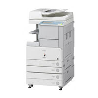
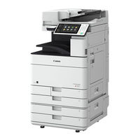
Canon 3225 Troubleshooting Manual (274 pages)
Brand:
Canon
| Category:
All in One Printer
| Size: 12.42 MB
Table of Contents
Manuals for the Machine
4
Printer Driver Installation
4
Troubleshooting
4
How this Manual Is Organized
6
Table of Contents
7
Preface
10
How to Use this Manual
10
Symbols Used in this Manual
10
Keys Used in this Manual
11
Displays Used in this Manual
11
Illustrations Used in this Manual
12
Abbreviations Used in this Manual
12
Trademarks
12
Operations and Terms Used in this Manual
13
Legal Notices
15
Product Name
15
FCC (Federal Communications Commission)
15
Laser Safety
16
International Energy Star Program
16
Ipv6 Ready Logo
17
Copyright
17
Third Party Software
17
The Software Subjected to the Other Conditions
18
The Software Licensed under the GPL/LGPL
18
Disclaimers
18
Legal Limitations on the Usage of Your Product and the Use of Images
19
Users in the U.S.A
19
Users in Canada
21
Utilisation Au Canada
23
Super G3
24
Important Safety Instructions
25
Installation
25
Power Supply
27
Handling
28
Maintenance and Inspections
30
Consumables
31
Telephone Equipment
31
Other Warnings
32
Periodic Inspection of the Breaker
33
Checking the Breaker
33
Check Sheet for the Periodic Inspection of the Breaker
36
Chapter 1 Before You Start Using this Machine
38
Installation Location and Handling
38
Installation Precautions
38
Avoid Installing the Machine in the Following Locations
38
Select a Safe Power Supply
41
Moving the Machine
42
Handling Precautions
42
Backing up Data
45
Parts and Their Functions
46
External View
46
Internal View
48
Control Panel Parts and Functions
49
Main Power and Control Panel Power
50
How to Turn on the Main Power
50
Control Panel Power Switch
55
Shutting down the Machine
55
Chapter 2 Routine Maintenance
62
Paper Drawers
62
Loading Paper
62
Adjusting a Paper Drawer to Hold a Different Paper Size
67
Paper Deck-Q1 (Optional)
70
Loading Paper
70
Envelope Feeder Attachment-C2 (Optional)
74
How to Use the Envelope Feeder Attachment
74
Preparing the Envelopes
76
Loading Envelopes
78
Changing Envelope Sizes
81
Feeder (DADF-U1) (Optional)
88
Replacing the Stamp Cartridge
88
Finisher-S1/Puncher Unit-R1 (Optional)
90
Replacing the Staple Cartridge
90
Removing Punch Waste
95
Finisher-Ae1/Saddle Finisher-Ae2/Puncher Unit-M1 (Optional)
98
Replacing the Staple Cartridge in the Stapler Unit
98
Replacing the Staple Cartridge in the Saddle Stitcher Unit
102
Removing Punch Waste
106
Replacing the Toner Cartridge
109
Routine Cleaning
114
Platen Glass and Cover
115
Manual Feeder Cleaning
116
Automatic Feeder Cleaning
121
Consumables
122
Reducing the Frequency of Paper Jams
126
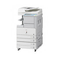
Canon 3225 Getting Started Manual (180 pages)
Brand:
Canon
| Category:
All in One Printer
| Size: 4.59 MB
Table of Contents
Manuals for the Machine
4
Printer Driver Installation
4
Troubleshooting
4
How this Manual Is Organized
6
Table of Contents
7
Preface
10
How to Use this Manual
10
Symbols Used in this Manual
10
Keys and Buttons Used in this Manual
11
Displays Used in this Manual
11
Illustrations Used in this Manual
12
Abbreviations Used in this Manual
12
Trademarks
13
Copyright
13
Disclaimers
13
Chapter 1 Flow of Settings
16
What this Machine Can Do
16
Sending Function
17
Network Scanning
18
Operations Required to Use the Machine
19
Confirm the Following Settings
19
License Registration
19
Sending E-Mail/I-Faxes
20
Sending Data to a File Server
21
Directly Sending Faxes from the Machine
23
Sending Faxes from a Computer Via the Machine
23
Netware Network Setup Procedures
23
Appletalk Network Setup Procedures
23
Printing from a Computer
24
Using the Machine as a Scanner
25
Managing the Machine from a Computer
26
Chapter 2 Using Optional Functions that Require License Registration
27
License Registration
28
Various Touch Panel Display Screens
30
Chapter 3 Before Connecting to a Network
32
Optional Equipment and System Requirements for Connecting to a Network
32
Printing or Sending a Fax from a Computer
32
Optional Equipment Requirements
32
System Requirements
33
Using E-Mail/I-Fax
35
Optional Equipment Requirements
35
System Requirements
35
Sending Data
36
Optional Equipment Requirements
36
System Requirements
36
Checking Your Network Environment
39
Sample Windows Network
39
Sample Macintosh Network
40
Sample UNIX Network
40
Using a Network with Various Types of Computers
41
Chapter 4 Settings Common to the Network Protocols
44
Network Environment Setup Procedures
44
Connecting the Machine to a Computer or Network
45
Connecting to a Network
45
Connecting to a USB Interface
47
Touch Panel Display Transition
49
Interface Settings
51
Communication Environment Setup
53
Chapter 5 Using a TCP/IP Network
62
TCP/IP Network Setup Procedures
62
Protocol Settings
63
Tcp/Ipv4 Settings
63
Tcp/Ipv6 Settings
69
Settings Common to Tcp/Ipv4 and Tcp/Ipv6
77
Confirming Tcp/Ipv4 Settings
84
Confirming Tcp/Ipv6 Settings
85
E-Mail/I-Fax Settings
86
Startup Time Settings
89
Setting up a Computer as a File Server
90
FTP Server Settings
91
Windows 2000/Xp/Server 2003/Vista
91
Unix/Linux
95
Mac os X
97
FTP Server for Imageware Document Manager Gateway
100
Webdav Server Settings
101
IIS for Windows 2000/2000 Server/Xp/Server 2003
101
Apache for Windows 2000/2000 Server/Xp/Server 2003/Unix/Linux/Mac os X
104
Chapter 6 Using a Netware Network (Windows)
107
Netware Network Setup Procedures
108
Protocol Settings
109
Setting up a Computer as a File Server
113
Chapter 7 Using a Netbios Network
118
Netbios Network Setup Procedures
118
Protocol Settings
119
TCP/IP Settings (Ipv4)
119
SMB and WINS Settings
119
Advertisement
Canon 3225 Service Manual (60 pages)
Brand:
Canon
| Category:
Printer
| Size: 2.69 MB
Table of Contents
Table of Contents
4
Product Overview, Configuration, and Accessories
6
Overview
6
Speed Comparisons (LTR) (Table 1)
6
Imagerunner 3245/3235 Series Comparisons (Table 2)
6
Imagerunner 3230/3225 Comparison (Table 3)
7
Improved Features (Table 4)
7
Configuration
9
Configuration (Table 5)
9
Main Unit Box Contents
13
Imagerunner 3245/3235/3230/3225 Box Contents (Table 6)
13
Accessory Options
14
Dadf-U1
14
Platen Cover Type M
14
Cassette Feeding Unit-Y3
14
Document Tray-J1
14
Envelope Feeder Attachment-C2
14
Inner 2 Way Tray-D1
14
Finisher-S1
15
Additional Finisher Tray-B1
15
Finisher-AE1
15
Saddle Finisher-AE2
15
Puncher Unit-M1
16
Cabinet-P1
16
Paper Deck-Q1
16
Copy Tray-J1
16
Print Controller Options
16
PCL Print Kit-AA1
16
PS Printer Kit-AA1
16
Direct Print Kit-F1
16
Encrypted Secured Print Software-C1
17
Barcode Printing Kit-A1
17
Fax Options
17
Super G3 Fax Board-AC1
17
Super G3 2 Nd Line Fax Board-AC1
17
Super G3 2 Nd /3 Rd - Line Fax Board-AC1
17
Universal Send Options
17
Color Universal Send Kit-P1
17
Universal Send Advanced Features Set-B1
17
Universal Send Security Feature Set-B1
18
Color Universal Send Kit-P1 Full Package
18
Digital User Signature Kit-B1
18
Send and Print Packages
18
Universal Send & PCL Print Package-AA1
18
Other System Options
18
System Upgrade RAM-A1
18
Additional Memory Type
18
Wireless LAN Board-A1
18
Access Management System Kit-A2
18
USB Memory Connectivity Kit-A1
19
Authorized Send Kit-V3
19
Web Access Software-G1
19
Workflow Composer-C1
19
Expansion Bus Board-E1
19
Security & Accessibility
20
Removable Hard Disk Drive Kit-C1
20
Secure Watermark-A1
20
HDD Data Encryption Kit-B5
20
HDD Data Erase Kit-B2
20
Braille Label Kit-E1
20
ADF Access Handle-A1
20
Voice Operation Kit-B1
20
Remote Operator's Software Kit-A3
20
USB Keyboard
21
Voice Guidance Kit-D1
21
IP Sec Board-A1
21
Dealer Sales/Service Authorization
22
Technician/System Engineer
22
Educational Training
22
Overview
22
Certification
23
Who Should Attend
23
Training Facilities
23
Prerequisites
23
What You will Learn
24
Course Highlights
24
Course Equipment
24
Student Feedback and Course Follow
25
Service Materials
25
Service Materials (Table 7)
25
Servicing Notes
26
License Management System (LMS)
26
Recommended System Engineer Requirements
27
Power and Plug Requirements
28
Main Unit Power and Plug Requirements (Table 8)
28
Installation Space Requirements
29
Installation Space Standard Configuration (Table 9)
29
Installation Space with Optional Accessories Configuration (Table 10)
29
Installation Space Full Configuration (Table 11)
29
Installation Times
30
Upgrading (Service Support Tool)
30
Estimated Installation Times (Table 12)
30
Computer Requirements for Upgrading
31
Hard Disk Drive Handling
31
Consumables
32
Consumable Parts
32
Main Unit Consumables List (Table 13)
32
Main Unit Consumable Parts List (Table 14)
32
DADF-U1 Consumable Parts List (Table 15)
33
Finisher-S1 Consumable Parts List (Table 16)
34
Paper Deck-Q1 Consumable Parts List (Table 17)
34
Finisher-AE1 / Saddle Finisher-AE2 Consumable Parts List (Table 18)
34
Periodic Maintenance
35
Main Unit Periodic Maintenance (Table 19)
35
DADF-U1 Periodic Maintenance (Table 20)
36
Customer Periodic Maintenance (Table 21)
36
Suggested End-User Customer Service Offerings
37
Monthly Copy Volume
37
Limited Warranty Support
37
End-User Limited Warranty Conditions
37
Monthly Copy Volume (Table 22)
37
Warranty Administration Reduction Program
38
Warranty Parts for Repair
40
E-Tag
42
On-Line Limited Warranty Credit Inquiry
44
Product Technical Support Offerings
47
Dealer Support Requirements
47
Canon USA Support Offerings
48
Canon USA Technical Support Center
48
Internet Support
49
Appendix
52
Specifications
52
Imagerunner 3245/3235 Series & Imagerunner 3230/3225 Main Unit (Table 23)
52
DADF-U1 (Table 24)
53
Cassette Feeding Unit-Y3 (Table 25)
53
Paper Deck-Q1 (Table 26)
54
Envelope Feeder Attachment-C2 (Table 27)
54
Copy Tray-J1 (Table 28)
54
Card Reader-C1 (Table 29)
54
Finisher-S1 (Table 30)
55
Finisher-AE1 (Table 31)
55
Saddle Finisher-AE2 (Table 32)
56
Puncher Unit-M1 (Table 33)
57
Puncher Unit-R1 (Table 34)
57
Inner 2 Way Tray-D1 (Table 35)
57
Warranty
58
Main Unit Limited Warranty
58
Drum Unit Limited Warranty
59
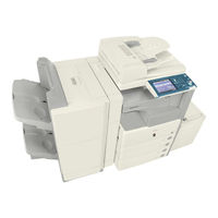
Canon 3225 Easy Operation Manual (60 pages)
All in One Printer
Brand:
Canon
| Category:
All in One Printer
| Size: 16.16 MB
Table of Contents
Table of Contents
1
Operation Guide
1
Manuals for the Machine
2
What You Can Do with this Machine
4
The Control Panel
6
Copying Functions
8
Operating the Express Copy Basic
8
Features Screen
8
Making a Copy
10
What You Can Do with this Machine (Regular Copy Basic Features Screen)
12
To Enlarge/Reduce an Image to Copy to a Different Size Paper
12
To Staple Sets of Output Together
12
To Interrupt a Long Copy Job to Make Priority Copies
13
To Copy Onto Irregular Sized Paper
13
To Make Two-Sided Copies
13
What You Can Do with this Machine (Special Features Screen)
14
To Copy Different Size Originals Together
14
To Copy Facing Pages in a Book
14
To Copy Multiple Originals Onto One Sheet of Paper
15
To Make a Booklet
15
To Erase the Dark Border When Copying a Book
16
To Add a Margin
16
To Add a Cover
17
To Recall Commonly Used Settings
17
To Scan Batches of Originals
18
To Add Page Numbers to Copies
19
To Add a Watermark to Copies
19
To Store Scanned Originals with Copy Settings
20
To Embed Hidden Text in the Background
20
To Combine Multiple Batches of Originals with Different Copy Settings
21
Overview of Copy Features
22
Sending/Facsimile Functions
24
Sending a Document
24
Ser Ver)
25
Sending a Fax
26
What You Can Do with this Machine (Address Book/Send Basic Features Screen)
28
To Register Commonly Used Destinations
28
To Recall the Last Settings
28
To Specify a File Format and Send a Document
29
If You Mainly Use One-Touch Buttons
30
When Sending Faxes/I-Faxes
30
To Automatically Forward Received
31
Faxes/I-Faxes
31
What You Can Do with this Machine (Scan Settings Screen)
32
To Send Documents Containing Photos Clearly
32
To Change the Scanned Document Size
32
To Automatically Change the Zoom Ratio According to a Specifi Ed Record Size
33
To Send Fine Text and Images Clearly
33
To Send Separately Scanned Documents at Once
33
What You Can Do with this Machine (Send Settings Screen)
34
To Add the Reply Destination to a Sent Document
34
To Specify the Time to Start Sending
35
To Send Notifi Cation of Completed Sending
35
To Confi Rm a Document before Sending
35
Overview of Sending/Fax Features
36
Canon 3225 Manual (3 pages)
Brand:
Canon
| Category:
All in One Printer
| Size: 1.93 MB
Canon 3225 Media Manual (2 pages)
B & W Copier
Brand:
Canon
| Category:
Copier
| Size: 0.14 MB
Advertisement
Related Products
Canon imageRUNNER 3300
Canon image RUNNER 3035
Canon image RUNNER 3045
Canon 3230
Canon image runner 3025
Canon image runner 3030
Canon 3100
Canon 3235 Series
Canon imageRUNNER 3220i
Canon imageRUNNER 3220n
Canon Categories
Printer
Digital Camera
All in One Printer
Camcorder
Scanner
More Canon Manuals
Login
Sign In
OR
Sign in with Facebook
Sign in with Google
Upload manual
Upload from disk
Upload from URL