
Related Manuals for NEC Super Script 4400


Summary of Contents for NEC Super Script 4400
-
Page 1: Maintenance Guide
NEC SuperScript 4400/4400N Maintenance Guide 18 September 1998 Part Number 703-A0240-001... - Page 2 The NEC Technologies product(s) discussed in this document are warranted in accordance with the terms of the Limited Warranty Statement accompanying each product. However, actual performance of each such product is dependent upon factors such as system configuration, customer data and operator control.
- Page 3 SuperScript 4400 — Maintenance Guide...
-
Page 4: Table Of Contents
Table of Contents 1: INTRODUCTION AND SETUP ........1 Overview . - Page 5 Printer Settings ......... . . 18 Using the Printer Operator Panel .
- Page 6 Factory Service Mode ........28 TCP/IP Setup .
- Page 7 Printing ..........50 Page Setup .
- Page 8 NEC PrintAgent Remote Printing ......88 NEC PrintAgent Pull Printing ....... . 88 System Requirements .
- Page 9 Configuring URLs ......... 95 Changing PWS Settings .
- Page 10 8: TROUBLESHOOTING ........203 Description .
- Page 11 ..Overview ..NEC Technical Support ..How to Contact NEC ..Consumables ..Maintenance Parts .
-
Page 12: 1: Introduction And Setup
INTRODUCTION AND SETUP VERVIEW The innovative NEC SuperScript™ 4400 color laser printer is the best value today for fast color and monochrome printing. The 4400 delivers high resolution, laser color output for business presentations and reports and is adaptable to changing business needs. The SuperScript 4400N network printer introduces the first web-based printing capability. -
Page 13: System Requirements
8 MB or more of RAM • Ethernet connection on the 4400N Web-Based Printing Requirements To use the web-based Pull Printing and NEC PrintAgent features, you need to have Microsoft’s Internet Explorer 4.01 SP1 web browser. Network Printing Requirements Supported Printing Environments... -
Page 14: Energy Saving
Energy Saving The SuperScript 4400 and 4400N printers meet the requirements of the Environmental Protection Agency’s Energy Star Computers program for printers. The purpose of this program is to promote the manufacturing and marketing of energy-efficient office automation equipment, thereby potentially reducing combustion-related pollution. (The Energy Star emblem does not represent EPA endorsement of any product or service.) Overview... -
Page 15: Superscript 4400 Series Cd
Administrator Setup This setup should only be used by system administrators who are familiar with the procedures for installing server software and network configuration. Use it to install and use network utilities, and set up servers for NEC PrintAgent Pull Printing. -
Page 16: Safety Instructions
AFETY NSTRUCTIONS To protect yourself and your equipment from possible damage, always follow these precautions. • Keep liquids away from the printer and protect the printer from dampness or spills. • Save the printer box and all packing materials that came with your printer in case you need to ship it later. •... -
Page 17: Unpacking
NPACKING Follow these steps to safely unpack the printer. Open the top cover of the packing box and remove the QuickStart poster. Remove the Accessory kit and Starter kit from the top of the printer. Turn the large plastic box screws at the bottom of the box to the left (A) and pull out to remove (B). Using your thumb and finger, remove the plastic screw sleeves from the box (C). -
Page 18: Checking Printer Contents
Power Cord • Toner Collector (installed next to the Toner Modules inside Front Cover of printer) QuickStart Poster Starter Kit NEC Paper Sample Pack Software Envelope •SuperScript 4400 User’s Guide •SuperScript 4400 Series CD •Adobe® Photo Deluxe CD Accessory Kit... -
Page 19: Identifying Printer Parts
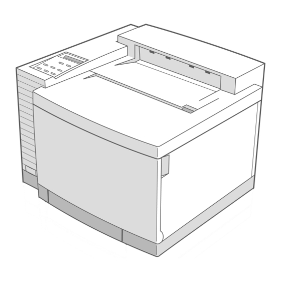
DENTIFYING RINTER ARTS Use the illustrations on the facing page to identify standard parts for the SuperScript 4400. Front View • Operator Panel—for displaying messages and configuring the printer • Power button—for turning on and off the printer • Top Cover—provides access to the Fuser Unit and inside of the printer (also serves as the Output Tray) •... - Page 20 Important Printer Parts FRONT INTERNAL VIEW FRONT VIEW Toner Module Racks Operator Panel Top Cover Paper Transfer Rollers Output Tray Power Top Cover Switch Release Button Toner Collector Front Cover Front Cover Latch Standard Paper Tray 1 BACK INTERNAL VIEW Transfer Drum Registration Rollers Paper Discharger...
-
Page 21: Installing The Photoconductor Belt Module
NSTALLING THE PHOTOCONDUCTOR BELT MODULE Make sure all packing materials and tape are removed from the printer. Open the Front Cover of the printer by grasping in the Front Cover Release latch (A). Open the Top Cover of the printer by sliding the Top Cover Release button forward (B) Flip up the photoconductor belt module Locking Levers inside the printer (C). -
Page 22: Installing The Fuser Oil Bottle And Fuser Cleaning Roller
NSTALLING THE USER OTTLE AND USER LEANING OLLER Open the Top Cover of the printer (A). Make sure the Lock Tabs are in the open position (B). Remove the orange Tension Release Pins, by pulling them up and out (C). note: You may have to pull hard to remove these. -
Page 23: Installing The Toner Modules
NSTALLING THE ONER ODULES Open the Front Cover of the printer(A). Note the color labels inside indicating where to place the different color Toner Modules (B) (C=Cyan, M=Magenta, Y=Yellow, and K=Black). Begin with Cyan. Remove the Toner Module from its plastic bag and rock it gently three or four times (C). Remove the protective tape from the module. -
Page 24: Loading The Paper Tray
OADING APER Paper Tray 1 can hold up to 250 sheets of medium weight paper—U.S. letter size, executive, UK quarto, folio, or A4. It also holds envelopes, transparencies, and sheets of labels. See Appendix X for a complete list of media that can be used. -
Page 25: Printing A Test Page
RINTING A Follow these steps to connect your printer to AC Power and print a test page. Make sure the power switch is turned off (button is out). Connect the Power Cord to the rear of the printer. Plug the other end of the Power Cord into a properly grounded outlet. WARNING! This printer is intended to be electrically grounded. -
Page 26: Connecting The Printer To Your Computer Or Network
ONNECTING THE RINTER TO OMPUTER OR ETWORK This section shows you how to connect your SuperScript 4400 Series printer to your computer or network. note: You can be connected to and receive data at the parallel port and Ethernet port at the same time. Connecting the 4400 Printer ®... -
Page 27: Connecting The 4400N Network Printer
Connecting the 4400N Network Printer If you have a SuperScript 4400N, you can connect to an Ethernet network. Use a Category 5 twisted pair cable with RJ-45 connectors for 10/100Base-T Ethernet. Follow these basic steps to connect the printer and verify that the NIC is installed and operating properly. Make sure your computer and printer are turned off. -
Page 28: Paper Handling And Special Media
Your starter kit includes a sampler of NEC Premium papers. See page xxx for information about ordering NEC premium papers and other printer supplies. If you do not have the NEC Premium papers, try to match them as closely as possible for the best printing results. Appendix Bxxx has more information about choosing media. -
Page 29: Superscript 4400 Settings
4400 S UPER CRIPT ETTINGS Printer Settings SuperScript 4400 printer settings give you many ways to customize your print job. There is often more than one place to change the same printer setting. These include • The SuperScript PostScript 3 and PCL 5e printer drivers •... -
Page 30: Postscript 3 Features
Sharp Edge Technology Specifies whether or not NEC’s Sharp Edge Technology (SET) should be used. SET is only available with 600dpi. It refines the print quality of characters and line art by smoothing the fine gradations along the edge of the printed image. -
Page 31: Postscript Options
PostScript Options There are several settings you can use to customize the way the driver processes print jobs PostScript Output Format These settings control the way the driver creates the PostScript language descriptions for page images. Optimize for Speed: Check this for faster printing. This option may cause a problem for some print jobs if the printer does not have enough memory. -
Page 32: Pcl 5E Features
Sharp Edge Technology Specifies whether or not NEC’s Sharp Edge Technology (SET) should be used. SET is only available with 600dpi. It refines the print quality of characters and line art by smoothing the fine gradations along the edge of the printed image. -
Page 33: Working With Fonts In Windows
ORKING WITH ONTS INDOWS Under most conditions your documents will print out well without any adjustment to font settings in your printer drivers. The Windows printer drivers have settings for specifying how TrueType fonts in your document how TrueType fonts in your document are matched to PostScript fonts in the printer. You may want to adjust these if your documents take a long time to print or the quality of the font is not satisfactory. -
Page 34: 2: Operator Panel
CHAPTER 2 OPERATOR PANEL VERVIEW The printer Operator Panel allows you to read printer messages and change printer settings directly at the printer. The diagram below identifies the different areas of the operator panel. This chapter describes • Operator Panel features, including indicator lights, the message display, and buttons •... -
Page 35: Operator Panel Features
PERATOR ANEL EATURES Indicator Lights The indicator lights on the Operator Panel communicate the operating status of the printer Light Mode Status Power Printer power is on or in POWER SAVE mode. (Green) Printer power is off. Warning Call for service (see page115). (Red) Normal state, no action is required. -
Page 36: The Message Display
The Message Display The Operator Panel status display is an LCD panel that shows status messages, alert messages, media types, and menu selections. When the printer is performing a job, the display indicates a printer status message, such as , etc. The standard display is , meaning the printer is ready for use. -
Page 37: Operator Panel Buttons
Operator Panel Buttons Operator panel buttons have different functions depending on whether the printer is online, offline, or in menu mode. The table below summarizes Operator Panel buttons. The operator panel menu tree and procedures for changing printer settings are discussed beginning on xxx. Button Mode Function... -
Page 38: Operator Panel Tasks
PERATOR ANEL ASKS This section describes some of the basic tasks you perform using the operator panel. More options are available in the Operator Panel Menu Tree described on page xxx. Taking the Printer Offline and Online Press the Online button to switch between the online and offline states. note: The printer must be offline before you can change any printer settings. -
Page 39: Printing 4400 Information Pages
Printing 4400 Information Pages You can print a number of different pages o with useful information about your printer. Follow these steps. Press Online. appears on the display. OFFLINE Press Menu. appears on the display. MENU - CONTROL Press Next until appears on the display. -
Page 40: Tcp/Ip Setup
TCP/IP Setup You can use the operator panel to enable and set up the TCP/IP networking parameters for the printer. This is particularly useful for setting the network IP address so you can use it as the printer’s URL in web-based printing. Follow these steps. - Page 41 Using the Operator Panel Menu Tree Press Select to move to a lower Press Next to display the menu or to select a setting when next item in a menu you are at the lowest level in Press the Online a menu button to take the CONTROL...
-
Page 42: Operator Panel Menus
Operator Panel Menus The Operator Panel has the seven main menus, described below (Default selections for each setting are marked with an asterisk (*). Control Menu Use this menu to cancel the current print job or reset the printer when the printer is in an error state. Selecting restarts the printer and causes it to reinitialize and perform a self-test. - Page 43 PostScript Menu Use this menu to configure the printer’s settings for the PostScript interpreter. POSTSCRIPT YES* / NO STARTUP PAGE YES* / NO PRINT PS ERRORS NEVER*, 20, 40, 60, 80, ... 280, 300 JOB TIMEOUT WAIT TIMEOUT NEVER, 20, 40, 60, 80, ... 240*,280, 300 PCL Menu Use this menu to configure the printer’s settings for the PostScript interpreter.
- Page 44 Communications Menu This menu has settings that enable the printer to receive print job from Parallel port or NIC, and to configure emulations and networking protocols. See page 29 for instructions on configuring TCP/IP parameters such as the network IP address. COMMUNICATIONS PARALLEL PORT YES* / NO...
- Page 45 Usage Status Menu Use the Usage Status menu to view the total number of pages printed. The printer resets the count whenever a Fuser Unit, or Belt Module is installed and you reset its status in the Operator Panel. USAGE STATUS TOTAL PAGE COUNT ROLLER REPLACE? BELT REPLACE?
-
Page 46: Overview
CHAPTER 3 PRINTER DRIVERS VERVIEW A printer driver is software that translates your computer data into a format that the printer can read and print out. You can access the printer driver software to change printer and document settings and manage fonts. First, you need to install the right printer driver for your system. -
Page 47: Windows 95/98
95/98 INDOWS Installing Printing Software Follow these steps to use the SuperScript Installer in Windows 95/98. Insert the SuperScript 4400 Series CD into the CD-ROM drive. The Installer will launch automatically. When prompted, select the Easy/Local installation option and click Next. Continue responding to the selections displayed in the installation dialog boxes. -
Page 48: Using The Windows 95/98 Printer Drivers
Using the Windows 95/98 Printer Drivers Windows 95/98 Printer Driver - System Tabs The General, Details, and Sharing tabs provide access to Windows features for setting up you printer. A brief description is provided here. For more information about settings on these tabs, see the Windows manual. General Tab Details Tab This tab provides general... - Page 49 Click any tab to view more printer settings. Click the Restore Defaults button to replace settings on the tab with factory defaults. current Click here to print page borders on your job. To order NEC Premium papers call 800-632-2326 SuperScript 4400 — Maintenance Guide...
- Page 50 Windows 95/98 Printer Driver - PostScript 3 Tabs (II) Click the Help button to view the complete Help file. Click the ? Help icon and click a setting on the driver to view more information about it. Click any tab to view more printer settings. Click the Restore Defaults button to replace current Graphics Tab settings on the tab with factory defaults.
- Page 51 Windows 95/98 Printer Driver - PCL 5eTabs Graphics Tab Paper Tab Use the Graphics tab settings Use the Paper tab to customize to define print quality. paper handling for the print job. Click the Help button to view the complete Help file. Click the ? Help icon and click a setting on the driver to view more information about it.
-
Page 52: Windows Nt 4.0
NT 4.0 INDOWS Installing Printing Software Follow these steps to use the SuperScript Installerxxx (SETUP.EXE) in Windows NT 4.0. Insert the SuperScript 4400 Series CD into the appropriate drive (in this example we use drive E:). Press the Start button and select Run from the Start pop-up menu. Windows displays the Run dialog box. Type E:\SETUP [Folder??] in the Command Line field. -
Page 53: Using The Windows Nt 4.0 Printer Driver
Using the Windows NT 4.0 Printer Driver Windows NT 4.0 Printer Properties The General, Ports, Scheduling, Sharing, The Device Options tab lets you change printer properties specific and Security tabs provide access to to the SuperScript 4400. (More settings are available when you Windows features for setting up your select Print or Print Setup from your application’s File menu. - Page 54 Windows NT 4.0 Document Properties - PostScript 3 You can change document settings using the Document Properties pages. To access these, select Print or Print Setup from your application’s File menu Page Setup Tab Use this tab for general page setup options. Advanced Tab Use this tab to access all Windows NT 4.0 printer driver settings.
- Page 55 Windows NT 4.0 Document Properties - PCL 5e You can change document settings using the Document Properties pages. To access these, select Print or Print Setup from your application’s File menu Page Setup Tab Use this tab for general page setup options. Advanced Tab Use this tab to access all Windows NT 4.0 printer driver settings.
-
Page 56: Windows 3.X
INDOWS Installation for Windows 3.x Follow these steps to install the printer drivers in Windows 3.x. Boot your system and start Windows. Insert the SuperScript 4400 Series CD into the appropriate drive (in this example we use drive E:). In the Windows Program Manager, select Run from the File menu. Windows displays the Run dialog box. Type E:\SETUP.EXE in the Command Line field. - Page 57 The Windows 3.x PostScript 3 Printer Driver Paper Tab Features Tab Use the Paper tab to customize This tab allows you to control the paper handling for the print job. special printer features. Fonts Tab PostScript Tab Use these settings to configure options You can use the Fonts tab to specify for the PostScript printing language.
- Page 58 Windows 3.x - PCL 5e Printer Driver Options The PCL 5e printer driver window has general document settings. Press the button to display more settings for adjusting graphic output. NEED NEW SHOT Click the Help button to view the complete Help file. Click Cancel to discard changes and close the driver.
-
Page 59: Mac Os
You can print from Mac OS version 7.1 and higher, to the SuperScript 4400N network printer over EtherTalk. Installing Printing Software Insert the SuperScript 4400 Series CD in your drive and double-click the SuperScript 4400 Installer icon. The installer prompts you to select installation preferences and creates the SuperScript 4400 Folder on your hard drive. - Page 60 Mac OS -Print Dialog Box Pull down the Settings menu to view more categories in the center panel. Mac OS...
- Page 61 SuperScript 4400 — Maintenance Guide...
-
Page 62: 4: Printer Options
If you have the SuperScript 4400N printer it is already equipped with a Network Interface Card (NIC). If you purchased the NEC SuperScript 4400, you can upgrade it by installing a network interface card (NIC). Use the directions in this section for installation... -
Page 63: Preparing The Printer
Remove the screw that holds the small 1.5” x 3.75” plate over the Network slot. Keep the screw (C). Preparing the Printer Network Slot SuperScript 4400 — Maintenance Guide... -
Page 64: Second, Install The Nic
Second, Install the NIC These steps are illustrated on the opposite page. Remove the NIC from its protective bag (A). Remove the mounting screw from the end of the standoff pin on the controller board (B). Hold the NIC so that its circuitry faces inside the printer and its LED’s face the back of the printer. Carefully align the standoff pin with the lower right corner of the NIC. -
Page 65: Third, Test The Nic
Third, Test the NIC Follow these steps to verify that the NIC is installed and operating properly. Connect the network’s twisted pair cable with RJ-45 connectors to the new network port on your printer (A). Reattach the power cord to the printer (B), plug in the printer. Turn on the printer (C). -
Page 66: Adding The Paper Tray 2 Unit
DDING THE APER Part #4005 Make sure the printer is turned off and disconnected. Make sure there is plenty of room around and above the printer to work. Find the packet of brackets and thumb screws and set aside. Remove the optional Paper Tray 2 unit from its packaging. Remove the .75”x 2” connector cable cover from the unit. - Page 67 WARNING! It takes two adults to lift the printer and assure that it is level. If the printer is tipped more than 1.5 degrees, oil will spill inside and cause damage. Locate the metal tab with screw hole on each side of the Paper Tray 2 unit. Take a metal bracket from the packet and hold it at a slight angle away from you.
-
Page 68: Adding Memory (Simm)
Remove SIMMs from the bottom memory sockets first. Install SIMMs to the top memory sockets first. The instructions that follow explain how to install memory in your printer yourself. You can also contact an NEC- authorized dealer and have more memory installed for a service fee. Call 800-632-4650. - Page 69 The following table lists the memory requirements, SIMM specifications, and advantages of added memory. Desired SIMMs to Use Advantages Memory 40MB Two 16MB and Improved print speed and performance Two 4MB SIMMs 48MB Two 16MB and Improved print speed and performance Two 8MB SIMMs 64MB Four 16MB or...
-
Page 70: Installing Simm
Installing SIMM Turn the printer off and disconnect it. Using a small phillips-head screw driver remove the two screws from the expansion slot on the rear of the printer (A), and pull out the Controller Board part way (B). To remove any un-needed SIMMs: Open the metal release brackets on each side of the memory socket at the same time (C). - Page 71 SuperScript 4400 — Maintenance Guide...
-
Page 72: Network Printing
CHAPTER 5 NETWORK PRINTING NETWORK SETUP To begin using the SuperScript 4400 Printer as a network printer, you must do the following setup tasks. Connect the 4400N to your network (see page 23). note: The 4400N printer already has a network interface card (NIC) installed. If you have a 4400 printer, you can purchase a Network Interface Upgrade Kit and install a NIC yourself. -
Page 73: Setup Options
Setup Options The SuperScript 4400 Series CD contains network printing tools to support the following configurations. Windows TCP/IP is required if you want to access and use the Network Administration Page to monitor and manage network printers. TCP/IP is also required to operate the printer in an IP protocol network (such as for peer to peer printing). -
Page 74: Network Printer Features
ETWORK RINTER EATURES Network Settings Page Each time you turn on the printer, the 4400N prints a Network Settings page. Another way to print a Network Settings page is: Go to the URL Configuration Page, the URL is http://<IP address>/configure.html. Click on the Network Administration link. -
Page 75: Setting The Printer Ip Address
Setting The Printer IP Address To take advantage of many of the network printer features, you must assign an IP address to the printer network interface card. There are several ways to do this. Using the Operator Panel to set the IP Address You can use the operator panel to enable and set up the TCP/IP networking parameters for the printer. - Page 76 Using MAP to set the IP Address The Management Access Program (MAP), runs only under Windows 95/98 and Windows NT 4.0. You can use MAP to locate and list SuperScript 4400 network printers connected to your network. Then you select one to go to its Network Administration Page and configure TCP/IP Setup.
-
Page 77: Resetting The Nic
Resetting the NIC If you change network settings, you may need to reset the printer NIC for the new settings to take effect. To reset Go to the URL Configuration Page, the URL is http://<IP address>/configure.html. Click on the Network Administration link. This displays the Network Administration Page. Click Reset in the System column, •... -
Page 78: Network Administration Page
ETWORK DMINISTRATION Your NIC has a built-in web that allows you to perform network administration tasks. Going to the Network Administration Page You must assign an IP address to your printer. Then you can use a web browser, such as Navigator or Internet Explorer, to access the Network Administration Page. - Page 79 Unit Status: Click here to view the current state for each protocol and NIC port available on your NIC. For each supported protocol (Novell NetWare, TCP/IP, or AppleTalk), the top line displays the protocols supported and if the protocol is enabled or disabled. Network Address: Click here to view the serial number and the Ethernet MAC (Media Access Control) address for the NIC.
-
Page 80: Using Map
SING The Management Access Program (MAP), runs only under Windows 95/98 and Windows NT 4.0. You use MAP to list SuperScript 4400 network printers connected to your network. Then you select one to go to its Network Administration Page for network administration options. MAP Operating Requirements To use MAP, you must have installed on your PC •... -
Page 81: Running Map And Selecting A 4400N
An example using MAP and the Network Administration Page to configure the printer for NetWare 4.x is shown on page 85. Management Access Program 3.20 [Refresh] [Help] Units supporting TCP/IP http://131.241.45.61/NEC_991142 NEC SuperScript 4400 Ethernet Card http://131.241.45.203/NEC_991149 NEC SuperScript 4400 Ethernet Card http://131.241.45.64/NEC_991151 NEC SuperScript 4400 Ethernet Card http://131.241.45.83/NEC_991650 Print Server Card http://131.241.45.191/NEC_991653 Print Server Card http://131.241.45.189/NEC_991655 NEC SuperScript 4400 Ethernet Card... -
Page 82: Windows Setup
INDOWS ETUP There are several ways you can configure your Windows workstation to access the 4400 network printer, depending on which version of Windows you are using and your system configuration. Below, under “Network Configuration Options,” are possible scenarios. Installing SuperScript 4400 Printer Drivers As you configure your network operating system, you will need to install a copy of the SuperScript 4400 printer driver onto each workstation that will be accessing the network printer. -
Page 83: Network Configuration Options
Network Configuration Options Windows 95/98 • If you have a NetWare network, see page 84 for NetWare 4.x setup, or page 86 for Netware 3.x setup. • If you have no network server, you can print directly to the network printer using the peer to peer software provided on the SuperScript 4400 Series CD. -
Page 84: Tcp/Ip Setup In Windows 95/98 And Windows Nt 4.0
If you have a NetWare network, see page 84 for NetWare 4.x setup, or page 86 for Netware 3.x setup. You can also use shared printing. TCP/IP Setup in Windows 95/98 and Windows NT 4.0 First, Install the TCP/IP Protocol In Windows, open the Network control panel. -
Page 85: Tcp/Ip Setup In Windows For Workgroups
TCP/IP Setup in Windows for Workgroups Accessing the 4400 network printer from Windows for Workgroups is supported in Microsof Shared printing or over a NetWare network. First, Install the TCP/IP Protocol You must obtain from Microsoft a special TCP/IP protocol stack that is compatible with Windows for Workgroups. Follow the instructions provided with that utility to install it. -
Page 86: Windows Peer To Peer Printing Setup
When the Add Printer wizard asks how the printer is attached, select Local printer. Specify NEC as the Manufacturer and NEC SuperScript 4400 as the Printer. Your peer to peer network printer will be listed under local printer ports and identified using the NIC serial number. -
Page 87: Removing Peer To Peer Software
In Windows NT 4.0, click the Start button, select Settings, then select Printers. Select the NEC SuperScript 4400 printer icon, and then select Properties from the File menu. Click on the Ports tab (the SuperScript 4400 driver installs to LPT1 by default). -
Page 88: Sdynamic Host Configuration Protocol
SDynamic Host Configuration Protocol Dynamic Host Configuration Protocol (DHCP) allows automatic assignment of IP address and other IP parameters for attached devices. The NIC works with DHCP in the following way. At power-up, the NIC broadcasts a DHCP request for an IP address. If a DHCP server is present, the request will be processed, and an IP address will be returned to the NIC. -
Page 89: Netware 4.X
Using NWADMIN First, Attach the Printer Log in to NetWare 4.x with administrator rights and open the NetWare Administrator window. Create Printer Object. a. Highlight the Organizational Unit or Organization where you want to create the print service in the Directory Tree. - Page 90 Second, Install the Printer Driver In Windows, use the Add Printer feature to install and configure a SuperScript 4400 printer driver in each workstation that will access the network printer. note: SuperScript 4400 printer drivers are on the Solutions CD that comes with the printer. Specify that the printer will be attached as a Network Printer, and set the Port to the printer queue you just created.
- Page 91 Complete these basic tasks to configure NetWare 3.x bindery-based services for your printer. Log in to NetWare 3.x with Administrator rights and start PCONSOLE. Define the Print Queue. a. Select Print Queue Information from the Available Options menu and press ENTER b.
-
Page 92: Netware 3.X
Assign the Print Queue. a. Select Queues Serviced By Printer and press . Highlight the desired printer on the Defined Printers ENTER list and press ENTER b. Press to display the Available Queues list. Select the desired queue and press . -
Page 93: Mac Os
Installing SuperScript 4400 MacOS Software Insert the 4400 xxx CD in your drive and double-click the SuperScript 4400 Installer icon. The installer prompts you to select installation preferences and creates the SuperScript 4400 Folder on your hard drive. Choosing the Printer Select Chooser from the Apple menu and make sure the AppleTalk Active button is selected. -
Page 94: Unix
UNIX Here we provide basic instructions for installing the printer on your UNIX system in Solaris 2.x and SCO. For additional information, refer to your operating system administration manuals. First, Configure the IP Address on the NIC The printer NIC must be assigned an IP address and routing parameters. We suggest you use the instructions on page xx for using the printer Operator Panel to set the Net (IP) Address. - Page 95 Adding a SuperScript 4400N to SCO Log into your system as root. Add the printer’s IP address you already assigned into the /etc/hosts file. Using lpsystem: follow these steps to open a terminal and enter the printer’s IP address from the command line. Set up the SuperScript 4400 printer with the NIC as a remote printer on a host that sends jobs to a Print Server using lpd.
-
Page 96: Web-Based Printing
WEB-BASED PRINTING VERVIEW The NEC PrintAgent is innovative software that allows you to print over the web in two ways, Remote Printing and Pull Printing. The NEC PrintAgent is powered by Redips® Core software, and available just by browsing to your Printer Home Page. -
Page 97: Nec Printagent Remote Printing
You can print to any SuperScript 4400N printer anywhere, as long as you have its URL. All you do is browse to the printer’s Home Page and download/install the NEC PrintAgent software to your system. When you print with that special driver, the job goes over the web to the printer, and printer status comes back to your desktop on the PrintAgent window. - Page 98 driver by selecting Settings and then Printers from the Windows Start menu. The Printers Window Restart for the new Driver to take effect. note: You can also install Remote Printing software from the SuperScript 4400 Series CD . Overview...
-
Page 99: Remote Printing From Your Desktop
Remote Printing From Your Desktop Now you can print as usual from your applications—just select Print from the File menu. The jobs will be sent to the printer using browser technology, and you can receive instant Printer Status reports. Getting Printer Status When you send a print job, the PrintAgent window opens automatically with status information. -
Page 100: Printagent Features
RINT GENT EATURES In addition to providing printer status and Help, PrintAgent buttons and menus provide access to the features described below. Details Button Click this to view more information about the printer. Tray information, emulations, pages per minute, and printer IP address are available. -
Page 101: Printagent Program Menus
PrintAgent to start up every time you print. To monitor the printer status, PrintAgent must be running. To start PrintAgent, press the Windows Start button, select Programs, and select NEC PrintAgent System to display PrintAgent commands. Choose Start. A red spider in a coffee cup appears in the Windows Tool Tray in the lower right-hand corner of the screen. -
Page 102: Printagent Window Menus
PrintAgent Window Menus The menu bar at the top of the PrintAgent window provides several options for configuring the PrintAgent and managing print jobs. File Menu Select Cancel Print Job to cancel the job currently being monitored. Select Print PostScript File to display a browser for selecting a PostScript file to transfer to the printer. Select Print Queue to display the Print Queue window to view and delete jobs. -
Page 103: Pull Printing
PrintAgent Core and Server Installation You must install the NEC PrintAgent core software, and the Pull Printing Server software. You can also install the Secondary File Server software. You can install all three at once using the Administrator Setup option. Follow these steps. -
Page 104: Configuring Urls
Configuring URLs Once the IP address is assigned to the printer, you can go to the printer URL Configuration Page to set URLs for the server(s). Launch your web browser and enter this URL http://<Printer IP Address>/configure.html This displays the printer’s URL Configuration Page. In the Pull Print Server text field, enter the IP Address of the Pull Printing Server as its URL. - Page 105 If you have a Secondary File Server, enter its IP Address as URL for the Driver, Help files, andPrintAgent software. You can also specify any URL as the Home page for clients. Click on the Submit Values to Printer button. note: Printer URLs can use either the printer’s IP Address, or the printer’s Domain Server Name (DSN), if one has been assigned.
-
Page 106: Changing Pws Settings
Changing PWS Settings This section describes changes you must make to Microsoft’s Personal Web Server for it to work as a Pull Printing Server. You will need to • Set the home directory • Add two virtual directories. Setting the Home directory If there is a Personal Web Server icon in the tool tray (lower right-hand corner of your screen), double-click the icon to bring up the Personal Web Manager. - Page 107 Adding Virtual Directories If you already have a cgi-gin directory at the same level as the htdocs directory, and a virtual directory called cgi- bin which points to the cgi-bin directory, you can skip the first five steps below. If the Pull Printing Server Installation Program did not detect a cgi-bin directory on the same level as the htdocs directory, a cgi-bin directory was added for you.
-
Page 108: Plug Ins
Modifying the Registry Entry If Pull Printing clients are experiencing problems getting status information, and there is a Proxy server between the Pull Printing Server and those clients, you should make the following registry changes in the Personal Web Server. Press the Windows Start button, select Run, and enter regedit to run the Registry Editor. -
Page 109: Pull Printing From Your Desktop
Pull Printing from Your Desktop Once the Pull Printing Server is running, any local user can Pull Print just by browsing to the Pull Printing Page. To pull print from your desktop, you must have • Microsoft’s Internet Explorer 4.01 SP1 and above (preferred) with Java 1.1 support. •... - Page 110 Print Queue frame. You will see a yellow highlight around the text. Click the Cancel button. After it is sent to the secondary server, the job can only be canceled using the the Admin dialog box from the NEC PrintAgent window.
-
Page 111: Pull Printing User Settings
Pull Printing User Settings You can customize your web browser settings to enhance your Pull Printing capabilities. Cookies If you would like the ability to save your printer settings and any watermarks you make, you must accept any cookies we set. This also gives you the ability to cancel any print jobs you send that are still in the print queue. A cookie is a small piece of data that the browser stores on your hard drive. -
Page 112: 6: User Maintenance
This chapter explains basic maintenance and cleaning procedures you must follow to maintain the high print quality and efficient operation of your NEC SuperScript 4400 printer. Included are instructions for the following maintenance tasks •... -
Page 113: Service Visit Schedule
Certain parts must be maintained or replaced by an authorized NEC field service engineer. When this is necessary call NEC Technical Support at 800-632-4650. They will put you in touch with an engineer in your area who can service your printer. -
Page 114: Replacing The Toner Modules
The Operator Panel will display an alert message when the toner level is getting low. To order an NEC SuperScript 4400 Toner Module contact your NEC printer dealer or call 1-800-NEC-INFO. The black replacement modules print approximately 10,000 pages. The yellow, magenta, and cyan replacement modules print approximately 6,000 pages each. -
Page 115: Replacing The Fuser Oil Bottle
EPLACING THE USER OTTLE Part number 20-212 Turn the printer off and allow it to cool (A). WARNING! The Fuser unit area may be very hot. Open the Top Cover (B). Open the Lock Tabs (C). Remove the used Fuser Oil bottle and discard it (D). note: Hold a piece of paper under the used Fuser Oil Bottle while removing it to avoid drips in the printer. -
Page 116: Replacing The Fuser Cleaning Roller
EPLACING THE USER LEANING OLLER Part number 20-211 Turn off the printer and allow it to cool (A). Open the Top Cover (B). Open the Lock Tab (C). Remove the used Fuser Cleaning Roller (D). Install the replacement Fuser Cleaning Roller (E). Close the Lock Tabs and the Top Cover of the printer (F). -
Page 117: Cleaning The Photoconductor Belt Module
LEANING THE PHOTOCONDUCTOR BELT MODULE The photoconductor belt module is sensitive to bright light and touch. Always wrap it in a soft dark cloth until you are ready to clean or install it. A dry cotton cleaning cloth is needed for this procedure Turn off and unplug the printer. - Page 118 11. Reset the Operator Panel usage information. note: Opening the Front Cover is necessary in order to make room for the photoconductor belt module. Cleaning Blade Do not touch edge! Cleaning the photoconductor belt module...
-
Page 119: Replacing The Photoconductor Belt Module
EPLACING THE PHOTOCONDUCTOR BELT MODULE Part number 20--205 Turn off the printer (A). Open the Front and Top Cover (B). Flip up the Lock Levers to release the photoconductor belt module (C). Pull the old photoconductor belt module straight up and discard it (D). Remove the black wrapper from the new photoconductor belt module and pull out the two tension release pins as shown (E). -
Page 120: Cleaning Inside The
LEANING NSIDE THE OVER Allow several minute for the printer to cool down and use only dry, lint-free cotton cloths or swabs for this procedure. Turn off and unplug the printer. Open the Back Cover (A) and following the directions below, clean the various parts of the Transfer Unit (B). Using a dry cotton cloth, clean any paper dust or toner buildup from the Registration Rollers. -
Page 121: Replacing The Fuser Unit
EPLACING THE USER Part number 20-219 Turn the printer off and allow it to cool. WARNING! The Fuser Unit area may be very hot. Open the Top Cover. Open the Lock Tabs (A). Remove the Fuser Oil bottle and put in plastic bag temporarily or discard if replacing with a new one (B). Remove the Fuser Cleaning Roller (C). -
Page 122: Cleaning The Laser Lens
LEANING THE ASER Cleaning the Laser Lens is only necessary when you find vertical white or light-color streaking in the colors. Open the Front Cover and Top Cover (A). Remove the four Toner Modules (B). Keep them level! Flip up the photoconductor belt module Lock Levers(C). Remove the photoconductor belt module (D) and loosely wrap it in a soft cloth or paper (E). -
Page 123: Replacing The Ozone Filter
EPLACING THE ZONE ILTER Part number xxx The Ozone filter needs to be replaced about every 12 months. A message on the Operator Panel will remind you of this. Follow these instructions to change the Ozone Filter. Slide open the Filter Cover located in back of the printer. Take the used Ozone Filter from inside the Filter Cover and discard it. -
Page 124: Cleaning The Outside Of The Printer
LEANING THE UTSIDE OF THE RINTER Use a clean cotton cloth and mild cleaner to clean the outside of the printer. note: Do not use strong solvents or abrasive cleansers on plastic parts of the printer. To clean the Paper Exit Rollers follow the instructions below: Turn off and unplug the printer Open the Top Cover slightly. - Page 125 SuperScript 4400 — Maintenance Guide...
-
Page 126: 7: Printer Maintenance
CHAPTER 7: PRINTER MAINTENANCE EPLACEMENT ROCEDURES FOR AINTENANCE ARTS Follow the procedures and cautions described below for the maintenance task. Do not perform any operation, disassembly, and modifications etc., that are not outlined in this Manual. Turn the power OFF and unplug the power cable from the outlet prior to starting disassembly. Prior to starting any work on this printer, read warnings related to "High Temperature", "High Voltage", and "Laser Radiation". - Page 127 Table 0-1: Size and Shape of Screw Class Code Name of Screw Remarks M-Thread Length Sharp BT3X8 Cross recessed head Used for tapping screw installation of BT3X12 10mm plastic parts BT4X8 BT4X10 10mm ST3X6 sS tight screqw Used for installation of parts to steel plate.
-
Page 128: Replacement Procedures For Maintenance Parts
7.1 Replacement of Covers Top Cover Operator Panel 7.1.4 Paper Exit Cover (Paper Exit Unit) 7.1.5 Main Switch Side Cover (R) Front Cover 7.1.2 (Front Cover Unit) Base Cover (R) Paper Cassette 7.1.9 [Front View] Side Cover (LU) Cleaner Cover 7.1.1 7.1.11 Side Cover (L) - Page 129 7 .1.1 Upper Side Cover (LU) Tools Phillips Screwdriver #2 Disassembly Procedures Open the paper exit unit. 10. Remove the set screw BT4 8 of side cover (LU). 11. Pressing the exterior of the side cover (L), unlock the interlock (three locations) with the side cover (LU).
- Page 130 7 .1.2 Side Cover (R) Tools Phillips Screwdriver #2 Disassembly Procedures Open the front cover unit. Remove the set screw BT4 X8 (1 pc.) of side cover (R) at the rear side. (Fig.7-3) Slide the side cover (R) to the arrow direction. (Fig.7-4) Remove the side cover (R).
- Page 131 7 .1.3 Side Cover (L) Tools Phillips Screwdriver #2 Disassembly Procedures Open the paper exit unit. Remove the side cover (LU). (See the item 7.1.1.) Remove the set screw BT4 8 (2 pcs.) of side cover (L). Remove the side cover (L). (Slowly pull up the side cover (L), and unhook the hook from the top cover.) Assembly Procedures Prepare a new side cover (L).
- Page 132 7 .1.4 Top Cover Tools Phillips Screwdriver #2 Disassembly Procedures Open the paper exit unit and the front cover Unit. Remove the side cover (LU). (See the item 7.1.1) Remove the side cover (L) and side cover (R). (See the item 7.1.2 and 7.1.3.) Top Cover Remove the operator panel assembly.
- Page 133 7 .1.5 Paper Exit Cover Tools Phillips Screwdriver #1, #2 Release arm Disassembly Procedures Fan Case Ass'y Harness Cover Paper Exit Cover Hook (L) Remove the side cover (LU). (See the item 7.1.1) Remove the side cover (L). (See the item 7.1.2) Remove the side cover (R).
- Page 134 7 .1.6 Rear Cover (L) (Transfer Unit Cover) Tools Phillips Screwdriver #1, #2 Disassembly Procedures Open the transfer unit. Remove the screw ST3 6 (1 pc.) from the stop holding the transfer unit to the frame. Remove the transfer unit. Remove the set screw BT3 10 (4 pcs.) of rear cover.
- Page 135 7 .1.7 Rear Cover (U) Tools Phillips Screwdriver #2 Disassembly Procedures Open the Transfer Unit. Unplug the power supply cable from the inlet. Remove the Rear cover. (See the item 7.1.8) Remove the set screw BT4 6 (1 pc.) of rear cover (U). Remove the rear cover (U).
- Page 136 7 .1.8 Rear Cover Tools Phillips Screwdriver #2 Disassembly Procedures Unplug the power cable from the printer. Remove the set screw BT4 8 (1 pc.) of rear cover. Remove the rear cover. Assembly Procedures Install a new rear cover. Plug the power cable into the printer. Paper Exit Cover Rear Cover(U) Rear Cover(L)
- Page 137 7 .1.9 Base Cover (R) Tools Phillips Screwdriver #2 Disassembly Procedures Remove the side cover (R). (See the item 7.1.3) Remove the set screw BT4 8 (2 pcs.) of base cover (R). Remove the base cover (R) from the base. Assembly Procedures Prepare a new base cover (R).
- Page 138 7 .1.10 Base Cover (L) Tools Phillips Screwdriver #2 Disassembly Procedures Remove the side cover (L). (See the item 7.1.2) Remove the set screw TS4 8 (2 pcs.) of base cover (L). Remove the base cover (L) from the base. Assembly Procedures Prepare a new base cover (L).
- Page 139 7 .1.11 Cleaner Cover Tools Cleaner Cover No tools are required. Disassembly Procedures Open the paper exit cover. Holding the ears, remove the cleaner cover. Assembly Procedures Paper Exit Cover Install a new cleaner cover. Close the paper exit cover. SuperScript 4400 —...
-
Page 140: 7.2 Replacement Of Circut Cards
7.2 Replacement of Circut Cards [ Layout of Circut Cards ] 7 . 2 . 7 7 . 2 . 4 P a n e l P . W . B 7 . 2 . 3 I O D 2 P . W . B 7 . - Page 141 7 .2.1 MCTL Circut Card. Tools Phillips Screwdriver #1, #2 Disassembly Procedures Remove the side cover (L). (See the item 7.1.2) Remove the top cover. (See the item 7.1.4) Remove the set screw ST3 6 (3 pcs.) of shield cover 'A'. Remove the shield cover 'A'.
- Page 142 Shield Cover A Side Cover(LU) Side Cover(L) MCTL P.W.B Shield Cover B Shield Case A Ass'y Replacement Procedures for Maintenance Parts...
- Page 143 7 .2.2 IOD1 Circut Card. Tools Phillips Screwdriver #1, #2 Disassembly Procedures Side Cover(LU) Remove the side cover (LU). (See the item 7.1.1.) Remove the top cover. (See the item 7.1.4.) Remove the set screw ST3 6 (3 pcs.) of shield (upper).
- Page 144 7 .2.3 IOD2 Circut Card. (with the base) Tools Phillips Screwdriver #1, #2 Slotted Screwdriver #1 Disassembly Procedures Remove the side cover (R). (See the item 7.1.3.) Disconnect all the harness connectors (15 pcs.) connected with the IOD2 Circut Card. Remove the C ring of registration clutch, cleaner clutch, and fuser clutch.
- Page 145 Side Cover (R) Fuser Clutch Cleaner Clutch Registration Clutch IOD2 P.W.B C ring SuperScript 4400 — Maintenance Guide...
- Page 146 7 .2.4 Panel Circut Card. (LCD inclusive) Tools Phillips Screwdriver #1, #2 Disassembly Procedures Side Cover(LU) Remove the side cover (LU). (See the item 7.1.1.) Remove the set screw BT4 10 (1 pc.) of the panel case assembly. Remove the set screw BT3 8 (4 pcs.) of panel Circut Card and LCD from the panel case assembly.
- Page 147 7 .2.5 Power Supply Unit Tools Phillips Screwdriver Slotted Screwdriver Disassembly Procedures Remove the side cover (LU). (See the item 7.1.1.) Remove the side cover (L). (See the item 7.1.2.) Remove the shield cover (upper). (See the item 7.2.1.) Remove the shield cover A.(See the item 7.2.1.) Remove the shield cover B.(See the item 7.2.1.) Disconnect all the harness connectors (5 pcs.) connected to the MCTL Circut Card.
- Page 148 Side Cover(LU) Shield Cover(L) Shield Cover A Shield Cover B Shield Case A Ass'y PS Fan Duct Base Cover(L) Top Cover (Front) (Rear) Inlet (Side View from Rear) Power Supply Unit Replacement Procedures for Maintenance Parts...
- Page 149 7 .2.6 High Voltage Unit Tools Phillips Screwdriver #1, #2 Disassembly Procedures Remove the side cover (LU). (See the item 7.1.1.) Remove the side cover (L). (See the item 7.1.2.) Remove the shield cover (upper). (See the item 7.2.1.) Remove the shield cover A.(See the item 7.2.1.) Remove the shield cover B.(See the item 7.2.1.) Disconnect all the harness connectors (5 pcs.) connected to the MCTL Circut Card.
- Page 150 Side Cover(LU) Side Cover(L) Shield Cover A Shield Cover B Shield Case A Ass'y PS Fan Duct High Voltage Power Supply Base Cover(L) Top Cover High Voltage Power Supply (Front Side) (Pear Side) (Side View from Rear Side) Power Supply Replacement Procedures for Maintenance Parts...
- Page 151 7 .2.7 Erase Lamp Tools Phillips Screwdriver #1, #2 Disassembly Procedures Remove the drum cleaner assembly. (See the item 7.6.3.) Holder Disconnect the harness connectors connected to the erase lamp. Remove the erase lamp from the holder. Assembly Procedures Install a new erase lamp. Install the erase lamp to the base frame.
-
Page 152: 7.3 Replacement Of Motor And Fan Units
7.3 Replacement of Motor and Fan Units [ Layout of Motors and Fans] 7.3.6 Ozon Fan 7.3.5 Heater Fan 7.3.1 Main Motor 7.3.2 7.3.4 Developer Drive Motor Controller Fan 7.3.3 Scanner Motor Replacement Procedures for Maintenance Parts... - Page 153 7 .3.1 Main Motor (MM)/Main Gear Unit Tools Phillips Screwdriver #1, #2 Disassembly Procedures Remove the photoconductor belt module. Remove the side cover (R). (See the item 7.1.3.) Remove the IOD2 Circut Card base. (See the item 7.2.3.) Disconnect all the harness connector connected with the main motor. Remove ST3 6 (3 pcs.), and the stay (R).
- Page 154 Top Cover Stay(R) OZone Fan Duct Side Cover(L) Drum Cleaner Solenoid Main Motor Fuser Clutch Main Gear Unit Cleaner Clutch ID2 P.W.B Registration Clutch Base Cover(R) Replacement Procedures for Maintenance Parts...
- Page 155 7 .3.2 Developer Drive Motor (DM)/Developer Drive Unit Tools Phillips Screwdriver #1, #2 Disassembly Procedures Remove the toner module. Remove the side cover (R). (See the item 7.1.3.) Remove the IOD2 Circut Card. (See the item 7.2.3.) Remove the harness guide. Remove the connector to be connected to the developer drive motor.
- Page 156 Ozone Filter Motor Developer Drive Unit Waste Toner Developer Clutch Harness Guide Developer Drive Motor Replacement Procedures for Maintenance Parts...
- Page 157 7 .3.3 Optical Unit (Scanner Motor inclusive) Tools Phillips Screwdriver #1, #2 Disassembly Procedures Remove the toner modules. Laser WARNING Label Remove the photoconductor belt module. Remove the cover 'C'. Cover 'C' is secured by the plastic nubs and hole at three locations in the front side and rear.
- Page 158 7 .3.4 Control Fan (CTFAN) Tools Phillips Screwdriver #1, #2 Disassembly Procedures Remove the side cover (LU). (See the item 7.1.1.) Controller Fan Remove the side cover (L). (See the item 7.1.2.) Remove the top cover. (See the item 7.1.4.) Remove the set screw ST3 6 (3 pcs.), and shield cover (upper).
- Page 159 7 .3.5 Fuser Fan (FUFAN) Tools Phillips Screwdriver #1, #2 Disassembly Procedures Remove the side cover (LU). (See the item 7.1.1.) Paper Exit Unit Remove the side cover (L). (See the item 7.1.2.) Remove the shield cover 'A'. Remove the paper exit unit. (See the item 7.1.5.) Remove the paper exit cover.
- Page 160 7 .3.6 Ozone Fan (OZFAN) Tools Phillips Screwdriver #1, #2 Disassembly Procedures Remove the toner module. Remove the side cover (R). (See the item 7.1.3.) Remove the IOD2 Circut Card. (See the item 7.2.3.) Remove the harness guide. Remove the connector to be connected to the developer drive motor. Remove the set screw ST3 6 (2 pcs.) of developer gear unit.
- Page 161 Ozone Fan Developer Drive Unit Waste Toner Developer Clutch Harness Guide Developer Drive Motor SuperScript 4400 — Maintenance Guide...
-
Page 162: 7.4 Replacement Of Clutches And Solenoids
7.4 Replacement of Clutches and Solenoids [ Layout of Clutches and Solenoids ] Drum Cleaner Solenoid Fuser Clutch Cleaner Clutch Transfer Solenoid Registration Clutch Paper Feed Clutch Developer Clutch Black (K) Developer Clutch Yellow (Y) Developer Clutch Magenta (M) Developer Clutch Cyan (C) (Developer Solenoids) Replacement Procedures for Maintenance Parts... - Page 163 7 .4.1 Paper Feeding Clutch (PCLU) Tools Phillips Screwdriver #1, #2 Slotted Screwdriver #1 Disassembly Procedures Remove the side cover (R). (See the item 7.1.3) Remove the IOD2 Circut Card base. (See the item 7.2.3) Remove the C ring fixing the paper feeding clutch. Remove the paper feeding clutch from the shaft.
- Page 164 7 .4.2 Registration Clutch (RECL) Tools Phillips Screwdriver #1, #2 Slotted Screwdriver #1 Disassembly Procedures Remove the side cover (R). (See the item 7.1.3.) Remove all the connector of registration clutch connected with IOD2 Circut Card. Remove the C ring from the shaft. Pull out the registration clutch from the shaft.
- Page 165 7 .4.3 Fuser Clutch (FUCL) Tools Phillips Screwdriver #1, #2 Slotted Screwdriver #1 Disassembly Procedures Remove the side cover (R). (See the item 7.1.3.) Remove the connector connected with IOD2 Circut Card. Remove the C ring from the shaft. Pull out the fuser clutch from the shaft. Fuser Clutch C ring Assembly Procedures...
- Page 166 7 .4.4 Cleaner Clutch (FBCL) Tools Phillips Screwdriver #1, #2 Slotted Screwdriver #1 Disassembly Procedures Remove the side cover (R). (See the item 7.1.3 .) Remove the connector of cleaner clutch from IOD2 Circut Card. Remove the C ring from the shaft. Pull out the cleaner clutch from the shaft.
- Page 167 7 .4.5 Developer Clutch (K, Y, M, C) Tools Phillips Screwdriver #1, #2 Slotted Screwdriver #1 Disassembly Procedures Remove the side cover (R). (See the item 7.1.3.) Remove IOD2 Circut Card. base. (See the item 7.2.3.) Remove the C ring of the suspect developer clutch (K,Y,M, or C) from the shaft. Pull out the subject developer clutch from the shaft.
- Page 168 7 .4.6 Transfer Solenoid (TRSOL) Tools Phillips Screwdriver #1, #2 Slotted Screwdriver #1 Disassembly Procedures Remove the side cover (R). (See the item 7.1.3.) Remove the IOD2 Circut Card. (See the item 7.2.3.) Remove the main gear unit. (See the item 7.3.1.) Remove the set screw ST3 6 (2 pcs.) of tension solenoid.
- Page 169 Top Cover Stay(R) Fan Duct Side Cover(L) Main Motor Transfer Solenoid Fuser Clutch Main Gear Unit Cleaner Clutch IOD2 P.W.B Registration Clutch Base Cover(R) SuperScript 4400 — Maintenance Guide...
- Page 170 7 .4.7 Drum Cleaner Solenoid (FBSOL) Tools Phillips Screwdriver #1, #2, Slotted Screwdriver #1 Disassembly Procedures Remove the side cover (R). (See the item 7.1.3.) Remove IOD2 Circut Card base. (See the item 7.2.3.) Remove the main motor/gear unit. (See the item 7.3.1.) Remove the set screw ST3 6 (2 pcs.) of drum cleaner solenoid.
-
Page 171: 7.5 Replacement Of Sensors
7.5 Replacement of Sensors [ Layout of Sensors ] Temperature Sensor 7.5.3 7.5.12 Paper Exit Sensor 7.5.6 Cleaning Roller Sensor Drum Jam Sensor 7.5.7 Oil Sensor 7.5.1-2 Interlock Switch(Top) 7.5.11 Toner Detecting 7.5.9 Sensor Belt Sensor 7.5.1-1 Interlock Switch 7.5.1-3 (Front) Interlock Switch(Rear) 7.5.8... - Page 172 7 .5.1-1 Interlock Switch (Front) Tools Phillips Screwdriver #1 Disassembly Procedures Remove the top cover. (See the item 7.1.4.) Remove the shield cover (upper). Remove the switch from the stay U. Remove the connector. Remove the switch from the switch case. Assembly Procedures Install a new switch to the switch base.
- Page 173 7 .5.1-2 Interlock Switch (Top) (for Paper Exit Unit) Tools Phillips Screwdriver #1, #2 Disassembly Procedures Remove the side cover (LU). (See the item 7.1.1.) Remove the top cover. (See the item 7.1.4.) Remove the set screw ST3 6 (2 pcs.), and the control fan assembly. Remove the set screw BT3 8 (1 pc.), and switch base from the control fan assembly.
- Page 174 Controller Fan Fan Case Interlock Switch Replacement Procedures for Maintenance Parts...
- Page 175 7 .5.1-3 Interlock Switch (Rear) Tools Phillips Screwdriver #1 Disassembly Procedures Remove the side cover (L). (See the item 7.1.2.) Interlock Switch Remove the transfer drum. (See the item 7.6.3.) Remove the set screw ST3 6 (2 pcs.) of transfer Transfer electrode Base electrode base.
- Page 176 7 .5.2 Paper Sensor (Paper Feeding Sensor PT1) Tools Phillips Screwdriver #1 Disassembly Procedures Remove the transfer drum. (See the item 7.6.1.) Remove the set screw ST3 6 (2 pcs.), and the paper guide (UR) assembly. Unlock the paper feeding sensor from the rear side of the hole where the paper guide (UR) has been removed. Remove the paper feeding sensor from the stay feeder.
- Page 177 Fixing Metal Paper Guide(UR) Transfer Unit Paper Sensor(PT1) Paper Guide Paper Guide(UL) SuperScript 4400 — Maintenance Guide...
- Page 178 7 .5.3 Paper Sensor (Paper Exit Sensor PT2) Tools Phillips Screwdriver #2 Disassembly Procedures Remove the paper exit cover. (See the item 7.1.5.) Disconnect the harness connector connected to the the paper exit sensor (PT2). Remove the paper exit sensor from the paper exit guide (paper exit stay). Assembly Procedures Install a new paper exit sensor to the paper guide.
- Page 179 Release arm Paper Exit Cover Hook (L) Paper Exit Inner Cover Hook (R) Spring Paper Sensor(PT2) SuperScript 4400 — Maintenance Guide...
- Page 180 7 .5.4 Paper Empty Sensor (PE)/OHP Sensor (OHP) Tools Phillips Screwdriver #1 Disassembly Procedures Remove the transfer unit. (See the item 7.6.1.) Remove the set screw ST3 6 (2 pcs.) of paper guide (L). Remove the paper guide (L). Remove the set screw ST3 6 (2 pcs.) of paper guide assembly (UR). Remove the connector connected with the sensor.
- Page 181 Transfer Unit Paper Guide Paper Guide(UL)Ass'y OHP Sensor Paper Sensor(PE) Paper Guide(UL)Ass'y (Side View from Rear Side) SuperScript 4400 — Maintenance Guide...
- Page 182 7 .5.5 Paper Size Sensor (PSU) Tools Phillips Screwdriver Disassembly Procedures Remove the side cover (L). (See the item 7.1.2. ) Remove the power supply unit. (See the item 7.2.5.) Remove the set screw ST3 6 (2 pcs.) of the paper cassette guide (L) assembly. Pull the paper cassette guide toward you.
- Page 183 7 .5.6 Drum Jam Sensor (DPJ) Tools Phillips Screwdriver #1, #2 Disassembly Procedures Remove the fuser unit. Remove the photoconductor belt module. Remove the drum cleaner. Remove the transfer drum. (See the item 7.6.3.) Remove the sensor cover. Disconnect all the connectors connected with the drum jam sensor. Remove the drum jam sensor from the stay B.
- Page 184 7 .5.7 Oil Sensor (OIL) Tools Phillips Screwdriver #1, #2 Disassembly Procedures Remove the fuser unit. Remove the side cover (LU). (See the item 7.1.1.) Remove the side cover (L). (See the item 7.1.2.) Remove the top cover. (See the item 7.1.4.) Remove the controller case 'A' assembly.
- Page 185 7 .5.8 Drum Encoder Sensor (EN) Tools Phillips Screwdriver #1, #2 Disassembly Procedures Remove the toner module. Remove the photoconductor belt Transfer Drum module. Remove the drum cleaner. Drum Encoder Sensor Remove the fuser unit. (EN) Remove the side cover (L). (See the item 7.1.2.) Remove the top cover.
- Page 186 7 .5.9 Belt Sensor (PBS) Tools Phillips Screwdriver #1, #2 Disassembly Procedures Remove the toner module. Remove the photoconductor belt module. Remove the drum cleaner. Remove the top cover. (See the item 7.1.4.) Remove the control fan assembly. (See the item 7.3.4.) Remove the set screw ST3 6 (2 pcs.) of the stay 'A'.
- Page 187 7 .5.10 Waste Toner Sensor (WTS) Tools Phillips Screwdriver #1, #2 Disassembly Procedures Remove the side cover (R). (See the item 7.1.3.) Lift up the bottle holder. (Remove the waste toner sensor by removing the hooked pawl.) Disconnect all the connectors connected with the waste toner sensor. Assembly Procedures Install a new waste toner sensor.
- Page 188 7 .5.11 Toner Sensor Assembly (TPD)/(TTR) Tools Phillips Screwdriver #1, #2 Disassembly Procedures (TPD): Remove the side cover (R). (See the item 7.1.3.) Remove the developer drive unit. (See the item 7.3.2.) Remove the set screw ST3 6 (2 pcs.) of toner sensor Circut Card. Disconnect all the connectors connected with the toner sensor Circut Card.
- Page 189 Toner Sensor(TTR) Fram Ass'y Toner Sensor(TPD) SuperScript 4400 — Maintenance Guide...
-
Page 190: 7.6 Replacement Of Rollers And The Drum
7.6 Replacement of Rollers and the Drum 7 .6.1 Transfer Unit Tools Phillips Screwdriver #1 Disassembly Procedures Remove the set screw ST3 6 (1 pc.) of transfer unit metal stop. Open the front cover unit. Remove the support shaft from the installation hole of frame. Remove the transfer unit. - Page 191 7 .6.2 Register Roller Tools Phillips Screwdriver #1 Slotted Screwdriver #1 Disassembly Procedures Open the transfer unit. Remove the roller fixing C ring at both sides. Remove the gear from the shaft. Remove the shaft support at the both sides. Remove the register roller.
- Page 192 7 .6.3 Transfer Drum Tools Phillips Screwdriver #1, #2 Disassembly Procedures Remove the toner module. Remove the photoconductor belt module. Remove the fuser unit. Remove the cleaner cover. Remove the drum cleaner. Open the transfer unit. Remove the top cover. (See the item 7.1.4.) Remove the control fan assembly.
- Page 193 Transfer Drum Stay A Ass'y SuperScript 4400 — Maintenance Guide...
- Page 194 7 .6.4 Paper Feed Roller/Separator Pad Tools Phillips Screwdriver #1 Disassembly Procedures Remove the paper feeding cassette. Remove the transfer unit. (See the item 7.6.1.) Remove the set screw ST3 6 (2 pcs.) of paper guide (L). Remove the paper guide (L). Remove the set screw ST3 6 (2 pcs.) of paper guide (UR).
- Page 195 Fixing Metal Paper Feed Roller Separator Pad Paper Guide(UR) Paper Guide Paper Guide(UL) Transfer Unit SuperScript 4400 — Maintenance Guide...
- Page 196 7 .6.5 Front Cover Unit Tools Phillips Screwdriver #1, #2 Disassembly Procedures Remove the side cover (L).(See the item 7.1.2.) Remove the base cover (L). (See the item 7.1.10.) Open the front cover unit. Remove the set screw BT4 8 (2 pcs.) of front cover (inner). Remove the coupling arm of waster toner tray.
- Page 197 Hinge arm Front hinge(L) Hinge holder Front Inner Cover Front Cover Unit SuperScript 4400 — Maintenance Guide...
- Page 198 7 .6.6 Paper Exit Roller Tools Phillips Screwdriver #1, #2 Disassembly Procedures Remove the paper exit unit. (See the item 7.1.5.) Remove the paper exit cover. (See the item 7.1.5.) Remove the C ring of both sides (left and right). Remove the shaft support at the both sides.
- Page 199 Heater Fan H.Harness Cover Release arm Paper Exit Cover Hook (L) Hook (R) Spring Discharge brush Metal Cring Paper Exit Roller Paper Exit Roller Metal Cring Cring SuperScript 4400 — Maintenance Guide...
- Page 200 7 .6.7 Discharger Brush Tools Phillips Screwdriver #1, #2 Disassembly Procedures Remove the paper exit unit. (See the item 7.1.5.) Remove the paper exit cover. (See the item 7.1.5.) Remove the paper exit front cover. Remove the set screw BT4 6 (2 pcs.) of discharger brush. Remove the discharger brush.
- Page 201 Heater Fan Release arm H.Harness Cover Paper Exit Cover Hook (L) Hook (R) Spring Discharge brush Cring SuperScript 4400 — Maintenance Guide...
- Page 202 7 .6.8 Waste Toner Feeder D (Stay 'A' Assembly) Tools Phillips Screwdriver #2 Disassembly Procedures Remove the photoconductor belt module. Remove the toner module. Remove the drum cleaner. Remove the side cover (LU). (See the item 7.1.1.) Remove the top cover. (See the item 7.1.4.) Remove the control fan assembly.
- Page 203 Stay A Ass'y SuperScript 4400 — Maintenance Guide...
- Page 204 7 .6.9 Fuser Connector Tools Phillips Screwdriver #1, #2 Disassembly Procedures Remove the fuser unit. Remove the side cover (L). (See the item 7.1.2.) Remove the shield case A assembly. Fuser Connector (See the item 7.2.5.) Remove the PN/PH connector connected with the DC power supply unit.
-
Page 205: 7.7 Replacement Of Fuser Unit
7.7 Replacement of Fuser Unit [Layout of Fuser Unit Parts] F.Cover (L) Cleaning Roller Back-up Roller Low Guide Frame F.Terminal (L) Thermister Cover Thermistor Ass'y Fusing Heater Fusing Roller F.Terminal (R) Oil Pan F.Cover B F Cover (R) Caution! 1. Fuser unit consists of important parts in terms of the safety. Therefore, replacement of parts or disassembly and maintenance work should be done at the appropriate facilities by skillful service personnel acquainted with electrical safety. - Page 206 7 .7 .1 Fusing Heater Lamp Tools Phillips Screwdriver #1, #2 Disassembly Procedures : See the layout of fuser unit parts. Remove the set screw ST3X6 (1 pc.) of F. cover (L), and F. cover (L). Remove the set screw ST3X6 (1 pc.) of F. cover (R), and F. cover (R). Pull F.
- Page 207 Back-up Roller Fuser Roller Terminal (L) Fuser Lamp (300W) Fuser Lamp (400W) Terminal (L) SuperScript 4400 — Maintenance Guide...
- Page 208 7 .7 .2 Fuser Roller Tools Phillips Screwdriver #1, #2 Disassembly Procedures : See the layout of fuser unit parts. Remove the fusing heater lamp (400W).(See the item 7.7.1.) Remove the set screw FST3X10 (1 pcs.) of F. terminal (R), and remove F. terminal (R) Remove the set screw ST3X6 (2 pcs.) of oil pan.
- Page 209 7 .7 .3 Back-Up Roller Tools Phillips Screwdriver #1, #2 Disassembly Procedures : See the layout of fuser unit parts. Remove the fusing heater lamp (300W).(See the item 7.7.1.) Remove the set screw ST3X6 (2 pcs.) of oil pan. Remove the oil pan. Remove the set screw ST3X6 (2 pcs.) of F.
- Page 210 7 .7 .4 Thermistor Assembly Tools Phillips Screwdriver #1, #2 Disassembly Procedures : See the layout of fuser unit parts. Remove the F. cover (R). Remove the F. cover (L). Remove the oil pan. Remove the F. cover 'B'. Remove the set screw BT3 8 of thermistor cover. Remove the thermistor cover.
- Page 211 Thermal Cut-off Thermal Cut-off D115 D125 Tube Tube Fuser Connector P Washer Back-up Roller Fuser Heater (300W) Fuser Roller Fuser Heater (400W) FST310 FST310 M210 Washer T. Adjustment P.W. B. Thermister Tube Wiring of Fuser Unit SuperScript 4400 — Maintenance Guide...
-
Page 212: 8: Troubleshooting
CHAPTER 8: TROUBLESHOOTING ESCRIPTION This chapter gives you the information you need to Troubleshoot problems that may occur with the SuperScript 4400/4400N printer and how to resolve them. The sections included in this chapter are: • Clearing Jams • Imaging Artifacts •... -
Page 213: Preventing Paper Jams
REVENTING APER This section explains how to prevent and remove paper jams. There are several things you can do to prevent paper jams. • Make sure the paper in not folded, wrinkled, or curled. • Do not overfill the paper trays. Paper Tray 1 and 2 have a fill-limit mark on the inside left side. •... -
Page 214: Removing Paper Jams
EMOVING APER • To avoid damage to rollers, always remove jammed paper gently. • Try to remove jammed paper without tearing it. Any pieces of media left in the printer, whether large or small, can obstruct the paper path and cause further jams. If, after clearing the paper jam, the jam message in the Operator Panel persists, open and close the Top Cover. - Page 215 If the paper did not come out easily, open the Top Cover and open the Pressure Release Tabs. Remove the jammed paper by pulling it from the bottom of the fuser (through the printer’s Back Cover, not from the top of the Fuser area. This prevents any unfused toner from dirtying the Fuser Rollers. WARNING! Be careful not to touch the Transfer Drum while removing jammed paper.
-
Page 216: Outer Jams
Outer Jams Outer jams occur in the fuser area. Jams of this type usually means that paper is stuck in the Fuser Roller/Output Area. Follow these steps to clear these kinds of jams. Turn off the printer and open the Top Cover. If there is a large amount of paper showing, gently pull it out. -
Page 217: Imaging Artifacts
MAGING RTIFACTS This section is provided to assist in the correction of artifacts that are discovered on the printed media. Sample Artifacts Catalogue To use this section select the artifact from the samples on the next few pages that represents the artifact you are experiencing, then turn to the page listed and follow the instructions on that page. - Page 218 Table 0-1: Sample Artifacts Catalogue Name/Description Sample Wrinkle/Image Migration Banding shadows of different optical density appear due to the wrinkle, image migration and color misregistration occurring on the print paper. Troubleshooting/Solution is on page 208. White Line I Vertical white line appears in a specific color area when test-printed in the four color mode (Stripe Mode) Troubleshooting/Solution is on page 209.
- Page 219 Table 0-1: Sample Artifacts Catalogue Name/Description Sample Vertical Line Vertical line appears in the printed image. Troubleshooting/Solution is on page 213. Vertical Staggering Image Printed image staggers in the vertical direction. Troubleshooting/Solution is on page 214. Banding Banding line appears in the horizontal direction. Troubleshooting/Solution is on page 215.
- Page 220 Table 0-1: Sample Artifacts Catalogue Name/Description Sample Toner Drop Toner spot stain is caused on the print by the toner dropping within the printer engine. Troubleshooting/Solution is on page 217 White Spot/Black Spot White spot and black spot appear on the print. Troubleshooting/Solution is on page 218.
- Page 221 Table 0-1: Sample Artifacts Catalogue Name/Description Sample Toner Streak Brush mark line of uneven optical density is caused in the image. Troubleshooting/Solution is on page 221. Mottle Variation of the optical density is found in the image. Troubleshooting/Solution is on page 222. Residual Image Image of the preceding page appears every other page.
- Page 222 Table 0-1: Sample Artifacts Catalogue Name/Description Sample Black Stain Back side of the print paper is stained. Troubleshooting/Solution is on page 225. White Print Blank page (no print at all) is outputted or specific color is missing (not printed) Troubleshooting/Solution is on page 226. Improper Fusing Printed image is partially missing.
-
Page 223: Artifacts Error Recovery
Artifacts Error Recovery Use this section to recover from the error condition that was selected in the previous section. The causes and counter measures listed for each item are in the order of probability. 1. Background - The background is smeared due to the toner spread. Main Causes Too small toner mass amount and charging amount in the development process. - Page 224 2. Missing Image at Edge - There are missing or peeling found in the image at edge. Main Causes Too small toner mass amount and charging amount in the development process. Life or failure of the belt module. OPC Belt Cartridge Toner Module K(Black) Y(Yellow)
- Page 225 3. Jitter - Uneven optical density appears periodically in the horizontal direction of printed image. Main Causes Failure of the main motor. a. Irregular rotation of the drive motor. b. Failure of the gears. c. Variation of Photoconductor belt running speed due to above reasons. d.
- Page 226 4. Ribbing - Light print occurs in the right or left side of image. Main Causes Slight tilt of the surface of printer table. (Tilt should be less than 1.5×) Low toner in the toner module. Countermeasures Level the printer. Replace the toner module with a new module.
- Page 227 5. Wrinkle/Image Migration - Banding shadows of different optical density appear due to the wrinkle, image migration and color misregistration occurring on the print paper. Main Causes Print paper other than the recommended paper is used. Paper discharger unit of transfer unit is not functioning. Fuser oil of fuser unit is nearly out.
- Page 228 6. White Line I - Vertical white line appears in a specific color area when test-printed in the four color mode (Stripe Mode) Main Causes Foreign particles adhered to Developer Roller of specific color in question. Foreign particles adhered to the Toner Module's Main Blade of specific color in question. Toner Module Developer Roller Toner Drop...
- Page 229 White Line II - Vertical white line appears from the leading edge to the trailing edge of printed image. Main Causes Dustproof Glass of Optical Unit is smeared with toner or foreign particles. OPC Belt Cartridge Toner Cartridge (K,Y,M,C) Optical Unit Paper Cassette Dustproof Glass Knob...
- Page 230 8. Vertical White Band - White band appears in the vertical direction of printed image. Main Causes Silicon oil on the transfer drum. Drum Cleaner Transfer Unit Transfer Drum Transfer Unit Paper Dischager Unit Adhered Silicone oil Transfer Roller Transfer Drum Paper Feeding Roller Countermeasures Wipe off the oil adhering to the transfer unit and surrounding area.
- Page 231 9. Black Line - Fine black line appears in the printed image. Main Causes Wire grid of the charger unit is smeared. photoconductor belt's surface is damaged. Foreign particles (paper dust, etc.) are stuck in between the cleaning blade and photoconductor belt. Debris adhering to the base of toner module's developer roller contacts to photoconductor belt.
- Page 232 10. Vertical Line - Vertical line appears in the printed image. Main Causes Foreign particles (dust, etc.) adhere to the parts located around the transfer drum, and consequently contact the toner image on the transfer drum. Drum Cleaner Fusing Unit OPC Belt Cartridge Cleaning Roller Cleaning Brush...
- Page 233 11. Vertical Staggering Image - Printed image staggers in the vertical direction. Main Causes The printer was bumped or was vibrating during the print process. Failure of the optical unit: Vibration from the rotation of scanner motor. Holes Cover C Interlock Optical Unit Front Cover Unit...
- Page 234 12. Banding - Banding line appears in the horizontal direction. Main Causes This is a transfer failure due to the shock caused when photoconductor belt's seam passes over the cleaning blade. OPC Belt Cartridge Cleaning Belt Belt Seam Countermeasures Replace the belt module with a new cartridge. (See Chapter 6) Imaging Artifacts...
- Page 235 13. White Band - White banding line appears in the horizontal direction, and consequently causes a missing image. Main Causes Installation failure of the transfer unit, and deformation of the transfer roller. Contact failure of the transfer roller's bias pole. Transfer Roller Cam Clutch failure.
- Page 236 14. Toner Drop - Toner spot stain is caused on the print by the toner dropping within the printer engine. Main Causes Toner drops on the transfer drum due to the break-down of the waste toner feeder's drum cleaner. a. Mylar of the waste toner feeder is deformed. b.
- Page 237 15. White Spot/Black Spot - White spot and black spot appear on the print. Main Causes Foreign particles adhering to the photoconductor belt or transfer drum. photoconductor belt or transfer drum is damaged. Foreign particles mixed in with the toner. Foreign particles adhering to the transfer roller.
- Page 238 16. Mixed Color Image - Mixed color image appears in the print. Main Causes Failure of toner module: Blade pressure of the developer roller is inappropriate or the blade is deformed. Registration error of toner module.. Toner Module Developer Roller Developer Blade Countermeasures Confirm that the toner module can be inserted smoothly.
- Page 239 17 . Color Misregistration - Color misregistration is caused between the two colors. Main Causes Photoconductor belt module is not properly installed. photoconductor belt module is deformed. Cleaning brush is unstable in the operation. Rotational load on the photoconductor belt module is excessive. Drum Cleaner OPC Belt Cartridge Toner Module...
- Page 240 18. Toner Streak - Brush mark line of uneven optical density is caused in the image. Main Causes Main blade of the developer unit and the reset roller is not normal Location of the toner module is not correct. Transport paddle in the toner module is deformed. Brush mark line appears in the continuous printing of high coverage (solid) pattern.
- Page 241 19. Mottle - Variation of the optical density is found in the image. Main Causes Transfer unit is not locked into place. Improper assembly of the transfer roller. THV output of DC high voltage unit is not normal. Failure of the toner module. Deformation of the paper.
- Page 242 20.Residual Image - Image of the preceding page appears every other page. Main Causes Cleaning failure due to the lifted cleaning brush of drum cleaner. Contact failure of the drum cleaner's bias pole. Failure of DC high voltage unit. Drum Cleaner Fusing Unit OPC Belt Cartridge Transfer Unit...
- Page 243 21. Insufficient Gloss - Gloss of the print is not sufficient. Main Causes Cleaning roller is stained. Fuser roller is deteriorated. Fusing Unit Cleaning Roller Oil Bottle Fuser Roller Back-up Roller Countermeasures Replace the cleaning roller with a new roller. (See Chapter 6) Replace the fuser unit with a new unit.
- Page 244 22. Black Stain - Back side of the print paper is stained. Main Causes Cleaning pad is stained. Fuser oil is low. Fuser roller and back-up roller is stained. Fusing Unit Cleaning Roller Oil Bottle Fuser Roller Back-up Roller Countermeasures Replace the cleaning roller with a new roller.
- Page 245 23. White Print - Blank page (no print at all) is outputted or specific color is missing (not printed) Main Causes Laser light path is blocked by paper or other material stuck at opening of optical unit. Transfer Solenoid is not functioning. There is no belt bias voltage (CBV) injected.
- Page 246 24. Improper Fusing - Printed image is partially missing. This proves that the fusing is improper. Main Causes Wrong selection of print media (label or envelope, etc.) at the computer side. Recommended paper is not used. Failure of the fuser unit. Fusing Unit Cleaning Roller Oil Bottle...
-
Page 247: Service Error Codes
ERVICE RROR ODES This section describes the troubleshooting procedures for Service Call Error Codes. Code Description of Error Cause of Error Clearance Method NVRAM Error 1. Failure of MCTL P.W.B. 1. Turn on and off the power switch. CPU EEPROM 2. - Page 248 Code Description of Error Cause of Error Clearance Method Developer Clutch (DCLC) 1. Loose/Broken connection 1. Check connection between ECN14 of IOD2 and Clutch (DCLC). 2. Incorrect voltage at 2. Check voltages below: +24V DCLC ON-N Voltage drop ( ) between ECN14-3 and ECN2-8 then, replace the clutch (DCLC) b) Voltage jump ( ) between ECN1-3 and...
- Page 249 Code Description of Error Cause of Error Clearance Method Developer Solenoid 1. Loose/Broken connection 1. Check connection between ECN14 of IOD2 and (PSL YM) Solenoid (PSL YM). 2. Incorrect voltage at 2. Check voltages below: (PSL YM) ON-N Voltage drop ( +24V ) between ECN3-11 and ECN2-8 then, replace the front cover unit...
- Page 250 Code Description of Error Cause of Error Clearance Method Developer Motor(DM) 1. Defective toner cartridge/ 1. Check for any unusual rotation noise while developer gear unit and printing then replace the suspected toner motor cartridge. If the noise continues replace the developer gear unit and motor.
- Page 251 Code Description of Error Cause of Error Clearance Method MCTL Main Motor(MM) IOD2 12CN MMCLK (Continued) MMRDY-N ECN1 MMON-N MMON-N MMREV-N MMCLK MMENC PGND ECN12 +24V-1 ECN2 IOD1 SGND +24V-1 +5V-1 PGND MMENC +5V-1 MMREV-N SGND 1. Re-install the belt cartridge. 1.
- Page 252 Code Description of Error Cause of Error Clearance Method Transfer Solenoid 1. Loose/Broken connection 1. Check the connections between: a) ECN8 of IOD2 and the solenoid connector. b) ECN2 of IOD2 and DCN9 of IOD1. c) DCN1 of IOD1 and 11CN of MCTL P.W.B. 3.
- Page 253 Code Description of Error Cause of Error Clearance Method Cleaner Clutch 1. Loose/Broken connection 1. Check the connections between: a) ECN11 of IOD2 and the clutch connector. b) ECN2 of IOD2 and DCN9 of IOD1. c) ECN1 of IOD1 and 11CN of MCTL P.W.B. 3.
- Page 254 Code Description of Error Cause of Error Clearance Method Belt Sensor (P.B.S) 1. Defective Belt Cartridge 1. If the belt cartridge leans to one side replace the cartridge and level the printer. 2. Belt Sensor Stained 2. Clean the belt sensor, replace the belt cartridge and level the printer.
- Page 255 Code Description of Error Cause of Error Clearance Method Fan Motor 1. Loose/Broken connection 1. Check the connections between: (Control Cooling) a) DCN13 of IOD1 and the fan motor connector. b) DCN1 of IOD1 and 11CN of MCTL P.W.B. 3. Defective Fan Motor 3.
- Page 256 Code Description of Error Cause of Error Clearance Method 1. Loose/Broken connection Heater Fan(HTFAN) 1. Check the connections between: a) DCN10 of IOD1 and the heater fan connector. b) DCN1 of IOD1 and 11CN of MCTL P.W.B. 3. Defective Heater 3.
- Page 257 Code Description of Error Cause of Error Clearance Method 1. Fuser Improperly Fuser Unit 1. Re-installe fuser unit. Installed (wire 3. C ontact failure due to 3. Replace fuser unit. cut/ damaged connector of fuser short unit error Loose/Broken connection of ther- 4.
- Page 258 Code Description of Error Cause of Error Clearance Method 1. Loose/Broken connection Optical Unit 1. Check these connections: (Beam Detecting Error) a) PDCN connector b) LCN1 and LCN of MCTL. 2. Optical Unit Failure 2. Replace Optical Unit. 3. MCTL P.W.B. Failure 3.
- Page 259 LCD Message Explanation Booting… First message to appear when the printer is powered up. OUT OF PAPER One of the paper trays is empty TRAY 2 UNSUPPORTED SIZE Lower tray contains paper size that is not supported by engine. PAPER MISMATCH LOAD Paper tray does not have the correct paper size as specified for <Paper Size>...
-
Page 260: Factory Service Mode Test Procedures
ACTORY ERVICE ROCEDURES This mode allows the service technician to perform diagnostic tests, and maintenance procedures on the printer engine. For instructions on entering this mode see Chapter 2 Table 0-2: Factory Service Mode Menus Code Item Code Item Item TEST PRINT NEXT CARE INFO CASSETTE TYPE... -
Page 261: Factory Service Mode Button Layout
Factory Service Mode Button Layout The button functions for this mode are different from the labels used for normal operations. See the tabel and diagram below for the new layout. Table 0-3: Factory Service Mode Power Warning Online Number Buttton Name Function NEXT Navigate to previous selection. -
Page 262: 35 Each Image
35 Each Image Number of created images per color used in printing can be confirmed. Press Select key after selecting EACH IMAGE mode. Using Scroll key, select the subject color, and then, press Select key. Number of created images per the selected color is displayed. (i.e. Yellow) Press the Clear key to clear the Control Panel LCD Using Scroll key, select other color, and then, press Select key to confirm the number of created images per each colors. - Page 263 42 FU Check Availability of oil in the fuser unit can be checked. Press Select key after selecting FU CHECK. note: Upon energized, fuser unit starts the heat-up process, and checks the availability of fuser oil. If the oil is available in the fuser unit, "GOOD"...
- Page 264 THV Tune Up This mode is used when transfer voltage needs to be adjusted due to the errors caused such as transfer failure on the media. The adjustment is to change the transfer voltage, subject to the media to be used, against the reference value 0 (zero) in the range between the step -4 and +4.
- Page 265 47 Total Page Set This mode can reset the number of total pages on NVRAM whenever executing NVRAM INITIAL or replacing the MCTL PWB. Press Select key after selecting TOTAL PAGE SET. Use Scroll key to designate or change the desired digit. Use Select key to input values to the blinking digit.
-
Page 266: Frequently Asked Questions
Can a SuperScript 4400 115-volt printer be converted to 220 volts in the field? No. The voltage must be specified when purchasing. What printer driver should I select if the NEC SuperScript Model 4400 drivers are not available on my computer? - Page 267 SuperScript 4400 — Maintenance Guide...
-
Page 268: Parts And Consumables
How to Contact NEC There are a number of ways to contact NEC or receive information about technical issues, products, and services. Contacting NEC Technical Support or Customer Service by Telephone In North America, call 800-632-4650 to speak to a representative about technical support, extended warranties, repairs, or customer service. -
Page 269: Consumables
Reaching the NEC Bulletin Board System You can use the NEC Bulletin Board System (BBS) to send messages and transfer files. The BBS number is 978-742-8706 Writing NEC You can mail your questions and comments to NEC Technical Support at the following address: Printer Technical Support, Dept. -
Page 270: Maintenance Parts
AINTENANCE ARTS The following is a list of maitenance parts required to service the SuperScript 4400/4400N printers: Table 0-2: Maintenance Parts Page Item Part Number Description Number Number 126107 Top Cover 126108 Side Cover (R) 126109 Side Cover (L) 126110 Upper Side Cover 126065 Panel Case Assy (ST) - Page 271 Table 0-2: Maintenance Parts Page Item Part Number Description Number Number 126141 Transfer Drum 126142 Paper Feeding Roller 126176 Seperator Pad 126144 Erase Lamp 126145 Oil Sensor 126064 Power Supply Unit (US) 126148 Power Cord (US) 126150 Fuser Connector 126152 Paper Feeding Clutch 126153 Registration Clutch...
- Page 272 Table 0-2: Maintenance Parts Page Item Part Number Description Number Number 126061 Panel Switch 126066 LCD Cover 340-A0001- Sub-Assy EPU Bd. 30129105 Lower Feeder Unit (Option) 30129118 Legal Cassette 4005 Network Upgrade Kit 126171 MCTL PWB Maintenance Parts...
- Page 273 SuperScript 4400 — Maintenance Guide...
-
Page 274: Appendix Aprinter Specifications
APPENDIX A PRINTER SPECIFICATIONS PERATING PECIFICATIONS Print speed Letter: 4-8 pages per minute color, 16ppm monochrome Warm-up: Maximum xx seconds [what?] Print method • Electrophotographic • Disposable color toner modules (C, Y, M, and K) Recommended Duty Cycle Monochrome: 20,000 prints per month Color: Up to 5,000 full color prints per month Processor Based on 64-bit IDT 4700, 100 MHz RISC processor... - Page 275 Color Support ® • Apple ColorSync 2.12 • Windows 95 ICM • All ICC-compliant color management systems Interface Ports • IEEE 1284-compliant parallel • Ethernet 10/100Base-T (4400N only) Power Requirements • 120V Model-120 VAC, ± 10%, 60 Hz, 8.3A Power consumption •...
- Page 276 Paper Handling Supported Paper Sizes SuperScript 4400 printer drivers support the following paper sizes. Paper Size Inches Millimeters Letter 8.5 x 11 216 x 279 Legal 8.5 x 14 216 x 356 8.3 x 11.7 210 x 297 Executive 7.25 x 10.5 184 x 267 UK Quarto 8 x 10...
- Page 277 Recommended Media Use NEC Premium papers (listed below) to ensure the best quality printed output. If you do not have the NEC Premium papers, try to match them as closely as possible for the best printing results. Premium Color Laser Paper 24 lb. Bond: A bright paper with a super smooth finish for brilliant color reproduction.
-
Page 278: Appendix Bmedia Specifications
Envelopes Recommended Media Use NEC Premium papers (listed below) to ensure the best quality printed output. If you do not have the NEC Premium papers, try to match them as closely as possible for the best printing results. Premium Color Laser Paper 24 lb. Bond: A bright paper with a super smooth finish for brilliant color reproduction. - Page 279 NEC offers a media sampler. One is included in the Starter kit that comes with your printer. Storing Printer Supplies Avoid storing printer supplies, such as Toner Modules and paper in direct sunlight, near an open flame, or in humid or dusty places.
- Page 280 Paper and Print Media You Should NOT Use in This Printer Paper jams or poor print quality may result from using print media that is not recommended for use in this printer or from print media that is damaged. Do not use media with the following characteristics. •...
-
Page 281: Appendix Csafety Information
APPENDIX C SAFETY INFORMATION This chapter provides safety information and product specifications for the SuperScript 4400 printer. As you operate your printer, please be aware of the following safety considerations. Ozone Emission The corona assemblies found in laser printers and photocopiers generate ozone gas (O3) as a by-product of the electrophotographic process. -
Page 282: Fcc Statement
Use a shielded and properly grounded I/O cable to ensure compliance of this unit to the specified limits of the rules. If your printer is the NEC SuperScript 4400N model or if you have installed the optional Network Interface Card (NIC), the printer meets the requirements of FCC Class A when connected to an Ethernet cable. - Page 283 This device complies with part 15 of the FCC Rules. Operation is subject to the following two conditions: This device may not cause harmful interference. This device must accept any interference received, including interference that may cause undesired operation U.S. Responsible Party: NEC Technologies, Inc. 1250 N. Arlington Heights Road, Address:...
-
Page 284: Appendix Dmoving Your Printer
APPENDIX D MOVING YOUR PRINTER This appendix gives you directions on how to safely move or ship your printer. Please follow these instructions carefully. Failure to do so may result in damage to the printer. OVING RINTER OCALLY To move the printer locally means that it can either be carried by two people or moved on a cart to its new location. Follow these steps: Turn the printer off and allow it to cool for 15 minutes. - Page 285 (B). note: If you need replacement packaging call NEC Customer Service at 800-632-4650 Open the Front Cover and remove the Toner Modules (C). Repack the Toner Modules in their original packaging.
- Page 286 Remove and discard the Toner Collector (H). If you have a new Toner Collector replace it now. To order a new Toner Collector call NEC Customer Service at 800-632-2326 and ask for part number 20-213. Do not ship your printer with a used Toner Collector.
- Page 287 SuperScript 4400 — Maintenance Guide...
- Page 288 13. Pack the printer for shipment as shown (K). 14. Do not forget the Power Cord and User Guide (unless you are shipping the printer for service). Slide box cover all the way down (L). 15. Attach the shipping box to its base tray. Insert the screw holders first (M), then the box screws themselves (N). 16.
- Page 289 SuperScript 4400 — Maintenance Guide...
-
Page 290: Maintenance Guide Appendum
Addendum SuperScript 4200N and 4400 Series Printers Maintenance Guide March, 1999 703-A0322-001... - Page 291 The information disclosed in this document, including all designs and related materials, is the valuable property of NEC Technologies and/or its licensors, as appropriate, reserve all patent, copyright and other proprietary rights to this document, including all design, manufacturing, reproduction, use and sales rights thereto, except to the extent said rights are expressly granted to others.
- Page 292 BOUT THIS DDENDUM URPOSE This addendum revises information in the August, 1998, edition of the NEC SuperScript 4400/4400N Maintenance Guide. note: The NEC SuperScript 4400/4400N Maintenance Guide is now called the NEC SuperScript 4200N and 4400 Series Printers Maintenance Guide .
- Page 293 Superscript 4200N and 4400 Series Maintenance Guide — Addendum...
- Page 294 ONTENTS Purpose ............... . i How to Use This Addendum .
- Page 295 Superscript 4200N and 4400 Series Maintenance Guide — Addendum...
-
Page 296: Overview
Revisions to the 4200N 4400 S UPER CRIPT ERIES RINTERS AINTENANCE UIDE VERVIEW Listed below are subjects that revise and add information to the SuperScript 4200N and 4400 Series Printers Maintenance Guide. Each subject is listed in the order in which it affects the Maintenance Guide. Each section in this addendum states which page of the Maintenance Guide is affected. -
Page 297: Factory Service Mode
ACTORY ERVICE Revises page 39 of the Maintenance Guide. Service mode is a state in which the printer can put into so that system, boot, PS, and network code can be serviced. Factory service mode is a state in which the printer can be put into so that the printer engine can be serviced. To enter factory service mode: 1. -
Page 298: Entering A Service Mode
The system code is upgraded by connecting a personal computer directly to the printer then transferring the upgraded code to the printer. The system code upgrade and an optional [Adobe Systems proprietary] installation program can be obtained from NEC Customer Support. Determining the System Code Version Before upgrading the system code, determine which version is currently installed. -
Page 299: Upgrading The 4400 Series Boot, Ps, And Network Codes
Upgrading 4400 Series code involves connecting a personal computer directly to the printer then transferring the upgraded code to the printer. The code upgrade and an optional [Adobe Systems proprietary] installation program can be obtained from NEC Customer Support. Determining the Boot Code Version If needed, you can determine which boot code version is already installed. - Page 300 To upgrade the 4400 Series boot code: Put the printer into service mode. From the operator panel, press Next until appears. BURN FLASH Press Select and appears. FLASH BURN ‘SELECT’ ENTERS Press Select and appears. FLASH BURN WAITING FOR DATA From the computer, move to the directory containing the file for the new code or the installation program.
- Page 301 To upgrade the 4400 Series Network Code: note: If an error occurs during the upgrade, the printer will automatically print the error message if Print PS Errors option is turned on. The default operating mode for the printer is with Print PS Error s on. Use the operator panel to check and turn on this option.
-
Page 303: Appendix E Error Messages
The controller board has 4 LEDs for indicating self-test errors. Should any of these LEDs be illuminated, the board must be sent to NEC for repair. However, one type of error may be resolved without sending in the board. If the LED labeled LED0 is illuminated and the rest are not, the problem may be resolved by re-installing the SIMMs or replacing them. - Page 304 PGRADE RROR ESSAGES During a Boot Code, PS Code, Network Code, and System Code upgrade, an error may occur and be displayed by the operator panel. The list shown below describes the upgrade error messages and their corrective action. Message Description Corrective Action Invalid Length...
- Page 305 Appendix F 4400 S ERIES PERATOR ANEL UTTONS This appendix is new to the Maintenance Guide. The following table summarizes the purpose of the of the 4400 Series operator panel buttons when the printer is in a specific operating mode. Button Mode Function...
- Page 306 Appendix G 4400 S ERIES PERATOR ANEL This appendix is new to the Maintenance Guide. LEDs located on the 4400 Series operator panel indicate printer operation status. The table shown below lists each LED and describes its meaning depending on what is the state of the LED. State Explanation Power...
- Page 307 Appendix H 4400 S ERIES PERATOR ANEL ESSAGES This appendix is new to the Maintenance Guide. This appendix lists three categories of messages that can appear on the operator panel display. • Status Messages • Alert Messages • Service Call Messages TATUS ESSAGES Status messages indicate the current operational state of the printer.
- Page 308 Message Explanation Line 1: SPOOLER JOB Line 2: Line 1: FIRST JOB Line 2: Line 1: RESETTING JOB Printer is resetting a job. Line 2: Line 1: OFFLINE Printer is offline. Line 2: Line 1: PRESS SELECT Presses Online button while the printer is processing a job or waiting for Line 2: TO CANCEL JOB additional input to complete the print job.
- Page 309 Message Explanation Line 1: PAPER MISMATCH Paper tray has papers but not the right type. Line 2: LOAD COM-10 TRAY Line 1: PAPER MISMATCH Paper tray has papers but not the right type. Line 2: LOAD DL TRAY Line 1: K-TONER EMPTY Black toner cartridge is empty Line 2:...
- Page 310 Message Explanation Line 1: TOP COVER OPEN Top panel is open. Line 2: Line 1: LOW FUSER OIL Fuser cleaning unit has about 30 pages left to end-of-life. Line 2: Line 1: FUSER ROLLER Fuser cleaning roller has about 1000 pages left to end-of-life. Line 2: NEAR END Line 1:...
- Page 311 Message Explanation Line 1: SERVICE CALL Magenta switching clutch error Line 2: Line 1: SERVICE CALL Cyan switching clutch error Line 2: Line 1: SERVICE CALL Black switching clutch error Line 2: Line 1: SERVICE CALL YK switching clutch error Line 2: Line 1: SERVICE CALL...
- Page 312 Message Explanation Line 1: SERVICE CALL Fuser temperature is continuously low after printable temperature error Line 2: Line 1: SERVICE CALL Fuser temperature is continuously high after printable temperature error Line 2: Line 1: SERVICE CALL Beam detector error Line 2: Line 1: SERVICE CALL Scanner motor error...
-
Page 313: Appendix I: Glossary
On the 4200N, the boot code and PS code are installed and upgraded simultaneously as a single set of code called a system. NEC tracks each system by giving it a version number that can be displayed by the operator panel. - Page 314 OTES...
- Page 315 Superscript 4200N and 4400 Series Maintenance Guide — Addendum...
- Page 317 NEC Technologies, Inc. 1250 N. Arlington Heights Rd. Itasca, IL 60143 www.nectech.com P/N: 703-A0322-001...
Need help?
Do you have a question about the Super Script 4400 and is the answer not in the manual?
Questions and answers