Canon iR1200 Series Service Manual
Hide thumbs
Also See for iR1200 Series:
- Service manual (424 pages) ,
- Installation procedure (24 pages)
Table of Contents
Advertisement
Advertisement
Chapters
Table of Contents
Troubleshooting

Related Manuals for Canon iR1200 Series


Summary of Contents for Canon iR1200 Series
-
Page 1: Service Manual
Service Manual iR1200 Series iR1570F Jun 17 2004... - Page 3 When changes occur in applicable products or in the contents of this manual, Canon will release technical information as the need arises. In the event of major changes in the contents of this manual over a long or short period, Canon will issue a new edition of this manual.
- Page 4 Introduction Symbols Used This documentation uses the following symbols to indicate special information: Symbol Description Indicates an item of a non-specific nature, possibly classified as Note, Caution, or Warning. Indicates an item requiring care to avoid electric shocks. Indicates an item requiring care to avoid combustion (fire). Indicates an item prohibiting disassembly to avoid electric shocks or problems.
- Page 5 Introduction The following rules apply throughout this Service Manual: 1. Each chapter contains sections explaining the purpose of specific functions and the relationship between electrical and mechanical systems with reference to the timing of operation. In the diagrams, represents the path of mechanical drive; where a signal name accompanies the symbol , the arrow indicates the direction of the electric signal.
-
Page 7: Table Of Contents
Contents Contents Chapter 1 Introduction 1.1 Product Specifications............................1- 1 1.1.1 Names of Parts ............................1- 1 1.1.2 Using the Machine ............................1- 6 1.1.3 User Mode Items............................1- 11 1.1.4 Maintenance by the User........................... 1- 38 1.1.5 Safety ................................ 1- 42 1.1.6 Product Specifications .......................... - Page 8 Contents 3.1.5Control Panel PCB............................3- 5 3.1.6Power Supply PCB ............................3- 5 3.1.7Analog Processor PCB ..........................3- 5 3.1.8Sensor PCB ..............................3- 5 3.1.9Laser Driver/BD PCB..........................3- 5 3.1.10Main Motor/Scanner Motor Driver ......................3- 5 3.1.11Printer Controller PCB ..........................3- 5 3.1.12NCU PCB (if equipped with fax functions) ....................
- Page 9 Contents 7.2.1 Jam Detection Outline..........................7- 3 7.2.2 Delivery Jams.............................. 7- 3 7.2.3 Stationary Jams ............................7- 3 7.2.4 Other Jams ..............................7- 4 7.3 Cassette Pick-Up Unit ............................7- 5 7.3.1Outline ................................. 7- 5 7.3.2Retry Pickup ..............................7- 5 7.3.3Detecting the Size of Paper .........................
- Page 10 Contents 9.2.1 Power Supply .............................. 9- 2 9.2.2 Protection Function ............................. 9- 4 9.2.3 Backup Battery ............................9- 4 9.2.4 Energy-Saving Function..........................9- 8 9.3 Parts Replacement Procedure .......................... 9- 10 9.3.1 Control Panel............................. 9- 10 9.3.2 Analog Processor PCB ..........................9- 10 9.3.3 Removing the DC Controller PCB......................
- Page 11 Contents 10.4.18 Delivery Stacking Tray ........................10- 48 Chapter 11 Maintenance and Inspection 11.1 Periodically Replaced Parts........................... 11- 1 11.1.1Periodically Replaced Parts........................11- 1 11.2 Durables and Consumables ........................... 11- 2 11.2.1Durables..............................11- 2 11.3 Scheduled Servicing Basic Procedure ......................11- 3 11.3.1Scheduled Servicing Chart ........................
- Page 12 Contents 12.5.3 Adjusting the Ellectrical System ......................12- 7 Chapter 13 Correcting Faulty Images 13.1 Making lnitial Checks............................ 13- 1 13.1.1Outline ..............................13- 1 13.1.2Making Initial Checks..........................13- 1 13.1.3Site Environment ............................. 13- 1 13.1.4Checking the Drum Unit.......................... 13- 1 13.1.5Checking the Paper ..........................13- 1 13.1.6Others...............................
- Page 13 Contents 15.2.13Downloading ............................15- 37 15.2.14Clearing ............................... 15- 38 15.2.15ROM Indication........................... 15- 38 15.2.16Resetting the Contact Sensor Position....................15- 39 15.2.17Service Mode Default Setting ......................15- 39 15.2.18Test Mode............................15- 55 15.2.19Service Report ............................. 15- 72 Chapter 16 Service Tools 16.1 List of Special Tools............................16-1 16.2 List of Solvents and Oils ..........................
-
Page 15: Chapter 1 Introduction
Chapter 1 Introduction... - Page 17 Contents Contents 1.1 Product Specifications............................1-1 1.1.1 Names of Parts............................. 1-1 1.1.1.1 External View (ADF type) ........................1-1 1.1.1.2 External View (copyboard type) ......................1-2 1.1.1.3 External View (ADF) ........................... 1-3 1.1.1.4 External Covers ............................ 1-4 1.1.1.5 Cross Section (Body)..........................1-5 1.1.1.6 Cross Section (ADF) ..........................
- Page 18 1.1.7.2 Printing Speed (Inch type) ........................1-52 1.1.7.3 Printing Speed (Inch type) ........................1-53 1.1.7.4 Mechanisms/Functions (ADF)......................1-53 1.1.7.5 Mechanisms/Functions (FAX)......................1-54 1.1.7.6 Mechanisms/Functions (FAX)......................1-60...
-
Page 19: Product Specifications
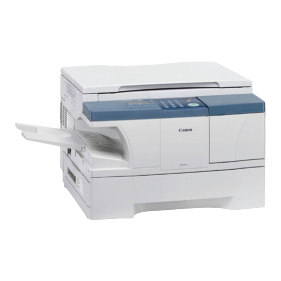
Chapter 1 1.1 Product Specifications 1.1.1 Names of Parts 1.1.1.1 External View (ADF type) 0006-2706 [14] [13] [12] [11] [10] F-1-1 T-1-1 [1] Reader unit slide lever [8] Control panel [2] Reader unit [9] Cassette [3] White sheet [10] Delivery tray [4] White roller [11] Power cord connector assembly [5] Copyboard glass... -
Page 20: External View (Copyboard Type)
Chapter 1 1.1.1.2 External View (copyboard type) 0006-2715 [12] [11] [10] F-1-2 T-1-2 [1] Reader unit slide lever [7] Control panel [2] Reader unit [8] Cassette [3] Copyboard cover [9] Delivery tray [4] Copyboard glass [10] Power cord connector assembly [5] Manual feed tray [11] USB cable connector assembly [6] Toner supply cover... -
Page 21: External View (Adf)
Chapter 1 F-1-3 T-1-3 [1] Drum shutter stopper [4] Right door [2] Cartridge cover [5] Shipping screw slot [3] Cartridge 1.1.1.3 External View (ADF) 0006-2722 F-1-4... -
Page 22: External Covers
Chapter 1 T-1-4 [1] Original placement area [3] Delivery slot [2] Open/close cover [4] Slide guide 1.1.1.4 External Covers 0007-3730 [1] ADF (copyboard cover) [2] Cartridge cover [3] Toner supply cover [4] Front cover [5] Delivery cover [6] Delivery upper cover [7] Delivery rear cover [8] Left cover F-1-5... -
Page 23: Cross Section (Body)
Chapter 1 1.1.1.5 Cross Section (Body) 0006-2724 [2] [3] [4] [5] [6] [7] [8] [9] [ 10] [23] [22] [20] [18] [16] [14] [12] [21] [19] [17] [15] [13] [11] F-1-7 T-1-5 [1] Contact sensor [13] Registration roller [2] Copyboard [14] Cassette pickup roller [3] Laser scanner motor unit [15] Developing cylinder... -
Page 24: Using The Machine
Chapter 1 1.1.1.6 Cross Section (ADF) 0006-2770 [2] [3] [4] [5] [6] [15] [14] [13] [12] [11] [10] F-1-8 T-1-6 [1] Slide guide [9] Original feed roller [2] Open/close cover [10] Contact sensor (body) [3] Original pickup roller [11] White roller [4] Original feed/separation roller [12] ADF registration roller [5] Original delivery tray... - Page 25 Chapter 1 T-1-7 Additional Functions Key Press it to bring up the user mode menu for making various settings and registering items. The key flashes when the machine is in user mode menu, and goes OFF in response to a press. Use it to refer to the Copy/Fax basic screen, various Settings screens, and error messages.
- Page 26 Chapter 1 [11] Start Key Press it to start making a copy or sending a fax. [12] # Key Press it to enter a "symbol"when registering fax/telephone number or when entering a fax telephone number. [13] Keypad Use it to enter a copy count or a value for Zoom, or when entering a fax telephone number.
- Page 27 Chapter 1 *2: Only for the iR1310/1330/1370F models. [1] [2] [3] Function [17] Fax Monitor Redial / Pause [16] Memory D.T. Reference Coded Dial [15] Report Tone/+ Directory [14] Delayed Space Transmission Receive Mode [13] Book Sending Delete Fax Resolution Clear [12] [11] [10]...
- Page 28 Chapter 1 *2: If equipped with fax functions. Coded Dial Key*1 Press it to use speed dialing. Directly Key*1 Use it to search for a one-touch or speed number using a name. Receive Mode Key*1 Press it to change the reception mode (faxtel, faxonly, DPRD*3, manual, ansmode).
-
Page 29: User Mode Items
Chapter 1 *2: Function key is ON. *3: Only for the iR1370F model. 1.1.3 User Mode Items 1.1.3.1 Outline 0006-2653 A press on the Additional Functions key in the control panel brings up the user mode menu. On the user mode menu, press the left/right arrow key to make menu settings or increase/decrease a value;... - Page 30 Chapter 1 2.ALARM VOLUME*1 VOLUME1 to 3 (1) 3.TX DONE TONE VOLUME1 to 3 (1) ERROR ONLY VOLUME1 to 3 (1) 4.RX DONE TONE VOLUME1 to 3 (1) ERROR ONLY VOLUME1 to 3 (1) *1: Only if equipped with fax functions. T-1-12 5.PRINTING END TONE VOLUME1 to 3 (1)
- Page 31 Chapter 1 VOLUME1 to 3 (1) 7.CALLING VOLUME 1 to 3 (2) 8.LINE MONITOR VOL. VOLUME1 to 3 (2) 4. STACK BYPASS SIZE T-1-13 BYPASS PAPER SIZE FREE SIZE SET ON LOADING BYPASS PAPER SIZE A4*2 LTR*3 STMT CUSTOM PAER SIZE 1.VERTICAL SIZE 76 to 216mm (216)
- Page 32 Chapter 1 *1: Only if equipped with fax functions. *2: Factory default for A/AB area. *3: Factory default for Inch area. 5. DRAWER PAPER SIZE T-1-14 A4*1 LTR/LGL*2 FOLIO FOOLSCAP 6. PRINT EXPOSURE T-1-15 5 settings (Center) 7. MP PAPERTYPE T-1-16 PLAIN PAPER TRACING PAPER...
- Page 33 Chapter 1 T-1-18 10. PRT FEED INTERVAL T-1-19 LONG INTERVAL NORMAL INTERVAL 11. DISPLAY LANGUAGE*3 T-1-20 ENGLISH FRENCH SPANISH GERMAN ITALIAN DUTCH FINNISH PORTUGUESE NORWEGIAN SWEDISH DANISH SLOVENE CZECH HUNGARIAN RUSSIAN *1: Factory default for A/AB area. *2: Factory default for Inch area. *3: This setting may be unavailable depending on the value set for service mode #5 TYPE.
-
Page 34: Copy Settings
Chapter 1 1.1.3.3 COPY SETTINGS 0006-2683 1. STD. IMAGEQUALITY T-1-21 TEXT ORIGINAL TEXT/PHOTO PHOTO 2. STANDARD EXPOSURE T-1-22 AUTO MANUAL 9 settings (Center) 3. STD ZOOM RATIO T-1-23 50 to 200% (100%) 4. STANDARD COPY QTY T-1-24 01 to 99 (01) 5. -
Page 35: Fax Settings*1
Chapter 1 T-1-26 330mm*1 356mm*2 7. PAPER SIZE GROUP T-1-27 INCH*2 AB*4 8. SHARPNESS T-1-28 1 to 9 (5) *1: Factory default for A/AB area. *2: Factory default for Inch area. *3: Factory default for A area. *4: Factory default for AB area. 1.1.3.4 FAX SETTINGS*1 0006-2692 T-1-29... - Page 36 Chapter 1 14400bps 9600bps 7200bps 4800bps 2400bps 4.RX START SPEED 33600 14400bps 9600bps 7200bps 4800bps 2400bps 2.UNIT NAME *1: Only if equipped with fax functions. 3.TX TERMINAL ID 1.TTI POSITION OUTSIDE IMAGE INSIDE IMAGE 2.TEL NUMBER MARK 4.DENSITY CONTROL LIGHT STANDARD DARK...
- Page 37 Chapter 1 1.REPORT 2.DELAYED TX 3.FAX MONITOR 4.MEMORY REFERENCE 5.BOOK SENDING 6.OFFHOOK ALARM 7.R-KEY SETTING*2 PSTN HOOKING EARTH CONNECTION PREFIX *1:Only if equipped with fax functions. *2:Only if equipped with fax functions and a 230V model. 2.REPORT SETTINGS 1.TX REPORT OUTPUT NO PRINT ERROR ONLY REPORT WITH TX IMAGE...
- Page 38 Chapter 1 REPORT WITH TX IMAGE 2.RX REPORT OUTP PRINT ERROR ONLY OUTPUT YES 3.ACTIVITY REPORT 3.TX SETTINGS 1.ECM TX 2.PAUSE TIME 01 to 15SEC (02) 3.AUTO REDIAL 1.REDIAL TIMES 01 to 10TIMES (02) 2.REDIAL INTERBAL 02 to 99MIN. (02) 3.TX ERROR RESEND RESEND TX FROM ERROR &...
- Page 39 Chapter 1 *1:Only if equipped with fax functions 4.ERASE FAILED TX 5.TIME OUT 4.RX SETTINGS 1.ECM RX 2.FAX/TEL OPT. SET 1.RING START TIME 00 to 30SEC (08) 2.F/T RING TIME 15 to 300SEC (15) 3.F/T SWITCH ACTION RECEIVE DISCONNECT 3.DRPD: SELECT FAX*2 NORMAL RING...
- Page 40 Chapter 1 SHORT- SHORT-LONG SHORT-LONG- SHORT OTHER RING TYPE 4.INCOMING RING RING COUNT 01 to 99TIMES (02) 5.MAN/AUTO SWITCH F/T RING TIME 01 to 99SEC (15) 6.REMOTE RX REMOTE RX ID 00 to 99 (25) *1: Only if equipped with fax functions. *2: Only for the iR1370F model.
- Page 41 Chapter 1 2.SELE REDU CE DIR VERTICAL ONLY HORIZ & VERTICAL 2.TONER SUPPLY LOW KEEP PRINTING RX TO MEMORY 6. SYSTEM SETTINGS 1.FAX DEFAULT 1.RESOLUTIO STANDARD FINE PHOTO SUPER FINE ULTRA FINE 2.BOOK TX SCAN SIZE A4*2 A5*2 LTR*2 LGL*2 SHEET 2.LOCK PHONE 1-23...
- Page 42 Chapter 1 *1: Only if equipped with fax functions. *2: This setting may be unavailable depending on the valve set for service mode SSSW>SW-14>bit 0,1. 3.COUNTRY SELECT*2 GERMANY FRANCE ITALY SPAIN HOLLAND DENMARK NORWAY SWEDEN FINLAND AUSTRIA BELGIUM SWITZERLAN PORTUGAL IRELAND GREECE...
-
Page 43: Fax Settings*1
Chapter 1 SOUTH AFRICA OTHERS *1: Only if equipped with fax functions. *2: This setting may be unavailable depending on the value set for service mode #5 TYPE. 1.1.3.5 FAX SETTINGS*1 0007-1181 T-1-30 1.USER SETTINGS 1.TEL LINE SETTINGS 1.USER TEL NO. 2.TEL LINE TYPE TOUCH TONE ROTARY PULSE... - Page 44 Chapter 1 2400bps 2.UNIT NAME *1: Only if equipped with fax functions. 3.TX TERMINAL ID 1.TTI POSITION OUTSIDE IMAGE INSIDE IMAGE 2.TEL NUMBER MARK 4.DENSITY CONTROL LIGHT STANDARD DARK 5.PROG. 1-TOUCH KEY 01 to 12 1.REPORT 2.DELAYED TX 3.FAX MONITOR 4.MEMORY REFERENCE 5.BOOK...
- Page 45 Chapter 1 7.R-KEY SETTING*2 PSTN HOOKING EARTH CONNECTION PREFIX *1:Only if equipped with fax functions. *2:Only if equipped with fax functions and a 230V model. 2.REPORT SETTINGS 1.TX REPORT OUTPUT NO PRINT ERROR ONLY REPORT WITH TX IMAGE OUTPUT YES REPORT WITH TX IMAGE 2.RX REPORT OUTP...
- Page 46 Chapter 1 3.TX SETTINGS 1.ECM TX 2.PAUSE TIME 01 to 15SEC (02) 3.AUTO REDIAL 1.REDIAL TIMES 01 to 10TIMES (02) 2.REDIAL INTERBAL 02 to 99MIN. (02) 3.TX ERROR RESEND RESEND TX FROM ERROR & 1ST PG ERROR PAGE ALL PAGES *1:Only if equipped with fax functions 4.ERASE FAILED TX 5.TIME OUT...
- Page 47 Chapter 1 1.ECM RX 2.FAX/TEL OPT. SET 1.RING START TIME 00 to 30SEC (08) 2.F/T RING TIME 15 to 300SEC (15) 3.F/T SWITCH ACTION RECEIVE DISCONNECT 3.DRPD: SELECT FAX*2 NORMAL RING DOUBLE RING SHORT- SHORT-LONG SHORT-LONG- SHORT OTHER RING TYPE 4.INCOMING RING RING COUNT 01 to 99TIMES...
- Page 48 Chapter 1 F/T RING TIME 01 to 99SEC (15) 6.REMOTE RX REMOTE RX ID 00 to 99 (25) *1: Only if equipped with fax functions. *2: Only for the iR1370F model. 5.PRINTER SETTINGS 1.RX REDUCTION 1.RX REDUCTION AUTO SELECTION FIXED REDUCTION 2.SELE REDU...
- Page 49 Chapter 1 ON*2 3.TONER SUPPLY LOW KEEP PRINTING RX TO MEMORY 6. SYSTEM SETTINGS 1.FAX DEFAULT 1.RESOLUTIO STANDARD FINE PHOTO SUPER FINE ULTRA FINE 2.BOOK TX SCAN SIZE A4*3 A5*3 LTR*3 LGL*3 SHEET 2.LOCK PHONE *1: Only if equipped with fax functions. *2: This setting may be unavailable depending on the valve set for service mode SSSW>SW-14>bit 0,1.
- Page 50 Chapter 1 GERMANY FRANCE ITALY SPAIN HOLLAND DENMARK NORWAY SWEDEN FINLAND AUSTRIA BELGIUM SWITZERLAN PORTUGAL IRELAND GREECE LUXEMBOUR HUNGARY CZECH RUSSIA SLOVENIA SOUTH AFRICA OTHERS *1: Only if equipped with fax functions. *2: Default setting (USA model only) *3: This setting may be unavailable depending on the value set for service mode #5 TYPE.
-
Page 51: Add. Registration*1
Chapter 1 1.1.3.6 ADD. REGISTRATION*1 0006-2705 T-1-31 1.1-TOUCH SPD DIAL 01 to 12 1. TEL NUMBER ENTRY 2. NAME 3. OPTIONAL SETTING 1. TX TIME SETTING 1 to 5 2. TX TYPE REGULAR TX SUBADDRESS TX 1. PASSWORD 2. SUBADDRESS POLLING RX 1. -
Page 52: Timer Settings
Chapter 1 2. SUBADDRESS 3. GROUP DIAL 01 to 12 1. TEL NUMBER ENTRY 2. NAME 3. TX TIME SETTING 1 to 5 *1: Only if equipped with fax functions. 1.1.3.7 TIMER SETTINGS 0006-2714 T-1-32 DATE/TIME SETTING AUTO CLEAR AUTO CLEAR TIME 1 to 9MIN. -
Page 53: Adjust./Clean
Chapter 1 7. SAT DATE SETUP YYYY YYYY YYYY 1.1.3.8 ADJUST./CLEAN 0006-2719 1. ROLLER CLEANING 2. CLEAN ADF ROLLER*1 3. RESTART PRINTER 4. MIX TONER *1: Only if equipped with ADF functions. 1.1.3.9 PRINT LISTS 0006-2720 T-1-33 1 USER DATA 2 SPEED DIAL LIST*1 1. -
Page 54: Count Check
Chapter 1 4. CODED(DETAIL) 1. NO SORT 2. SORT 5. GROUP DIAL LIST 3 CANCEL REPORT *1: Only if equipped with fax functions. 1.1.3.10 COUNT CHECK 0006-2738 101: TOTAL T1: XX*2 201: COPY T1: XX*3 000*3 000*3 000*3 000*3 *2: Cannot be changed. -
Page 55: Reports Generating (Automatically Generating Reports: If Equipped With Fax Functions)
Chapter 1 Name of report Operation Docement memory list*1 Select fax mode. Press Function key and Report key in this order. Use the Left or Right Arrow key to select a list to print, then press OK key. Activity report*1 *1: Only if equipped with fax functions. -
Page 56: Maintenance By The User
Chapter 1 Name of report Settings Memory clear list If the machine remains without power for a specific period of time (about 2 hr or more) while an image exists in its memory, the power of the vanadium lithium secondary battery (BAT2) will become exhausted. -
Page 57: Other Cleaning
Chapter 1 follows: 1) Place an A4 or larger sheet of plain paper in the manual feed tray. 2) Press the Additional Functions key, and hold down the Right Arrow key or the Left Arrow key until the LCD indicates '6. ADJUST/CLEAN'. 3) Press the OK key. -
Page 58: Points To Note When Handling The Cartridge
Chapter 1 data.) g. Keep it out of reach of children. h. Keep the temperature between 0 deg and 35 deg C (32 deg and 95 deg F). 1.1.4.5 Points to Note When Handling the Cartridge 0007-3727 a. Do not shake the cartridge after setting the toner bottle. b. - Page 59 Chapter 1 F-1-14 e. Do not disassemble the cartridge. f. Do not subject the cartridge to unnecessary vibration or impact. In particular, do not force down on the photosensitive drum through the shutter found under the cartridge. g. Do not keep the cartridge inside the machine when moving the machine. Be sure to put the cartridge in its protective bag, or wrap it in thick cloth to avoid light.
-
Page 60: Safety
Chapter 1 Whenever possible, keep the drum unit intact with the developing unit. If you must separate the drum unit and the developing unit as when checking image faults, be sure to keep it in a protective bag to prevent damage to the drum surface. -
Page 61: Cdrh Requirements
Chapter 1 1.1.5.2 CDRH Requirements 0006-2833 The Center for Devices and Radiological Health (CDRH) of the US Department of Health and Human Services put into force a set of requirements with a view to regulating laser-related products on August 2, 1976. The requirements apply to laser products produced on August 1, 1996, or later, and all laser products must comply with them if they are to be marketed in the US. -
Page 62: Safety Of The Toner
Chapter 1 F-1-16 The label is attached to covers inside the machine used to block out laser radiation. 1.1.5.4 Safety of the Toner 0006-2836 The machine's toner is a non-toxic material consisting of plastic, iron, and small amounts of dye. If toner came into contact with your skin or clothes, remove as much of it as possible with dry tissue, and wash with water. -
Page 63: Product Specifications
Chapter 1 1.1.6 Product Specifications 1.1.6.1 Mechanisms/Functions 0007-0834 Body Desk top (ADF standard type, copyboard standard type) Copyboard Fixed Light source type Lens type CIS (contact sensor) Photosensitive medium OPC drum (30-mm dia.): Drum unit Reproduction method Indirect electrostatic Charging method Roller contact Exposure method Semiconductor laser... - Page 64 Chapter 1 Reproduction Ratio 3R2E 3R2E (Inch configuration) Reproduction ratio 50% to 200% (1% increments) Warm-up time 8.5 sec (after plug in)/1.0 sec (after pressing Energy Saver key) First print time 13 sec or less 21.5 sec (after plug in) 18 sec (after pressing Energy Saver key) Continuous 99 pages max.
-
Page 65: Others
Chapter 1 1.1.6.2 Others 0006-2639 Operating environment 0 deg to 35 deg C/32 deg to 95 deg C (temperature range) Operating environment 35% to 85% (humidity range) Operating environment 0.61 to 1.01 hPa (0.6 to 1 atm) (atmospheric pressure) Power supply rating 120 V (50/60 Hz), 230 V (50/60 Hz) Power consumption Maximum:... -
Page 66: Mechanisms/Functions (Adf)
Chapter 1 Reproduction Ratio Direct 1 : 1.000 Reduce I 1 : 0.500 Reduce II 3R2E (Inch 1 : 0.647 Reduce IV 1 : 0.786 Enlarge II 1 : 1.294 configuration) Enlarge IV 1 : 2.000 1.1.6.4 Mechanisms/Functions (ADF) 0006-2701 Pickup method Auto pickup/delivery (top separation by double-pad) - Page 67 21.6Kbps, 19.2Kbps, 16.8Kbps, 14.4Kbps, 12Kbps, TC9.6Kbps, TC7.2Kbps, 9.6Kbps, 7.2Kbps, 4.8Kbps, 2.4Kbps With automatic fallback function Coding MH, MR, MMR, JBIG Error correction ITU-T ECM Canon express protocol None Transmission output from 0 to -15 dBm level Minimum receive input -43 dBm (at. V.17)
- Page 68 Chapter 1 Polling Polling transmission: None Polling reception: Receives from a fax in automatic transmission mode One touch locations Max. 12 Confidential reception None Confidential None transmission Remote reception Method ID call# (ID input method) Remote (with ID call#) 2 digits (Default: 25) Memory reception Auto dialing Telephone number digits...
-
Page 69: Function List
Chapter 1 Redial Interval: 2 min. (from 2 to 99 min. can be selected in user data) Count: 2 times (from 1 to 10 times can be selected in user data) Memory backup Backup contents: dial registration data, user data, service data, time Backup IC: 128 Kbyte SRAM Backup battery: Lithium battery 3.0 V DC / 560 mAh Battery life: Approx. - Page 70 Chapter 1 Ratio Size Paper size copies/min Cassette Manual feed tray*1 IV (200.0%) postcard -> A4R *1: If the manual feed tray is in use, the copying speed is indicated assuming that the paper size setting is correct. *2: AB-configured paper only. *3: In the case of "Special paper 2 mode"...
- Page 71 Chapter 1 1.1.7.3 Printing Speed (Inch type) 0007-0818 T-1-41 Ratio Size Paper copies/min size Cassette Manual feed tray*1 Direct LTR (216 × 279mm / 8.5" x 11.0") LGL (216 × 356mm / 8.5" x 14.0") STMTR (139 × STMT 216mm / 5.5" x 8.5") Reduce I (50.0%) STMT...
- Page 72 Chapter 1 Items Specifications Original reading Stream reading Stack 30 sheets or less (if A4/LTR or smaller) 15 sheets or less (if LGL) Mixed original sizes Yes (only if of the same paper configuration) Original AE detection Original size recognition Stamp Power supply From host (5 VDC and 24 V)
- Page 73 33.6Kbps, 31.2Kbps, 28.8Kbps, 26.4Kbps, 24Kbps, 21.6Kbps, 19.2Kbps, 16.8Kbps, 14.4Kbps, 12Kbps, TC9.6Kbps, TC7.2Kbps, 9.6Kbps, 7.2Kbps, 4.8Kbps, 2.4Kbps With automatic fallback function Coding MH, MR, MMR, JBIG Error correction ITU-T ECM Canon express protocol None Transmission output level from 0 to -15 dBm Minimum receive input level -43 dBm (at. V.17)
- Page 74 Chapter 1 Ultrafine 406.4 dpi (16 dots/mm) (Interpolated) Vertical: Standard 97.79 dpi (3.85 lines/mm) Fine 195.58 dpi (7.7 lines/mm) Superfine/Ultrafine 391.16 dpi (15.4 lines/mm) Scanning density adjustment Light, Standard, Dark: The density level of each mode can be selected by the user mode menu.
- Page 75 Chapter 1 Polling Polling transmission None Polling reception Receives from a fax in automatic transmission mode One touch locations Max. 12 Confidential reception None Confidential transmission None Remote reception T-1-46 Method ID call# (ID input method) Remote ID (with ID call#) 2 digits (Default : 25) Memory reception T-1-47...
- Page 76 Chapter 1 No. of reseruation Max. 20 Broadcast transmission Locations Max. 122 (One-touch : 12, Coded speed dial : 100) Numeric button: 10) Group button addresses Max. 111 (One-touch : 11, Coded speed dial : 100) Relay broadcasting originating None Relay broadcasting None...
- Page 77 Chapter 1 Document memory list b) Service report System data list System dump list Key history report Counter report Print spec report T-1-48 Transmitting terminal identification Items Time, telephone No. (max 20 digits), senders ID, address, number of transmitted pages (ma x 3 digits) Address Can be registered with one-touch/ coded speed dial keys...
- Page 78 Chapter 1 Image data backup Backup contents Memory reception, delayed transmission and broadcast transmission image data, activity management report Backup IC 16 Mbyte SDRAM Backup coding method JBIG Backup battery Rechargeable vanadium lithium battery 3.0V DC/ 50 mAh Battery life 40 cycles with 100% discharge (Temperature 77 deg F (25 deg C)) Time...
- Page 79 33.6Kbps, 31.2Kbps, 28.8Kbps, 26.4Kbps, 24Kbps, 21.6Kbps, 19.2Kbps, 16.8Kbps, 14.4Kbps, 12Kbps, TC9.6Kbps, TC7.2Kbps, 9.6Kbps, 7.2Kbps, 4.8Kbps, 2.4Kbps With automatic fallback function Coding MH, MR, MMR, JBIG Error correction ITU-T ECM Canon express protocol None Transmission output level from 0 to -15 dBm Minimum receive input level -43 dBm (at. V.17)
- Page 80 Chapter 1 Ultrafine 406.4 dpi (16 dots/mm) (Interpolated) Vertical: Standard 97.79 dpi (3.85 lines/mm) Fine 195.58 dpi (7.7 lines/mm) Superfine/Ultrafine 391.16 dpi (15.4 lines/mm) Scanning density adjustment Light, Standard, Dark: The density level of each mode can be selected by the user mode menu.
- Page 81 Chapter 1 Polling Polling transmission None Polling reception Receives from a fax in automatic transmission mode One touch locations Max. 12 Confidential reception None Confidential transmission None Remote reception T-1-53 Method ID call# (ID input method) Remote ID (with ID call#) 2 digits (Default : 25) Memory reception T-1-54...
- Page 82 Chapter 1 No. of reseruation Max. 20 Broadcast transmission Locations Max. 122 (One-touch : 12, Coded speed dial : 100) Numeric button: 10) Group button addresses Max. 111 (One-touch : 11, Coded speed dial : 100) Relay broadcasting originating None Relay broadcasting None...
- Page 83 Chapter 1 Document memory list b) Service report System data list System dump list Key history report Counter report Print spec report T-1-55 Transmitting terminal identification Items Time, telephone No. (max 20 digits), senders ID, address, number of transmitted pages (ma x 3 digits) Address Can be registered with one-touch/ coded speed dial keys...
- Page 84 Chapter 1 Image data backup Backup contents Memory reception, delayed transmission and broadcast transmission image data, activity management report Backup IC 16 Mbyte SDRAM Backup coding method JBIG Backup battery Rechargeable vanadium lithium battery 3.0V DC/ 50 mAh Battery life 40 cycles with 100% discharge (Temperature 77 deg F (25 deg C)) Time...
-
Page 85: Chapter 2 Installation
Chapter 2 Installation... - Page 87 Contents Contents 2.1 Making Pre-Checks ............................2-1 2.1.1 Selecting the Site ............................2-1 2.2 Unpacking and Installation..........................2-2 2.2.1 Before Starting ............................2-2 2.2.2 Installation Procedure..........................2-2 2.2.3 Unpacking ..............................2-2 2.2.4 Fitting the Cartridge ............................ 2-3 2.2.5 Fitting the Toner bottle..........................2-3 2.2.6 Putting Paper in the Cassette ........................
-
Page 89: Making Pre-Checks
Chapter 2 2.1 Making Pre-Checks 2.1.1 Selecting the Site 0006-2646 T-2-1 The site must meet the following requirements; if possible, visit the user's before the machine is delivered: The site must offer a power outlet whose rating is as specified volts (-/ +10%) and which may be used exclusively for the machine. -
Page 90: Unpacking And Installation
Chapter 2 Unpacking 2.2.3 Unpacking 0006-2670 Installation 1) Unpack the machine, and take out the attachments. Check to see that none of the following is missing: - cassette 2.2.1 Before Starting 0006-2663 - delivery tray - cartridge (durm unit and developing unit) Go through the following before starting to install the - power cord machine:... -
Page 91: 4Fitting The Cartridge
Chapter 2 F-2-2 6) Open the cartridge cover. F-2-5 3) Close the cartridge cover, and put back the reader unit. 2.2.5 Fitting the Toner bottle 0006-2713 1) Open the toner supply cover. F-2-3 7) Store away the securing member removed in step 4 in the shipping screw slot. -
Page 92: 6Putting Paper In The Cassette
Chapter 2 F-2-8 4) Holding the toner bottle steady with one hand, firmly and slowly pull the sealing tape tab with the Before Complete F-2-10 other hand to remove the sealing tape completely. Throw the tape away. To avoid breaking the tape, do not pull it at an angle. F-2-11 6) Close the toner supply cover. -
Page 93: 7Putting Paper In The Manual Feed Tray
Chapter 2 F-2-13 F-2-16 2) Put paper in the cassette, under the claw must 3) Place the paper (with the side to be copied onto indicate what [1] and [2] are. facing up). F-2-17 4) Adjust the slide guide to suit the width of the paper. F-2-14 3) Slide in the cassette until it stops. -
Page 94: 9Connect The Power Cord
Chapter 2 Use interface cables that comply with specifications of the machine. USB cable specifications: 5 m or shorter. Parallel interface cable specifications: 3 m or shorter (Compliant IEEE1284, bi-directional communication) F-2-21 2.2.11 Setting the Printer Functions 0006-2744 1) Install printer drivers, and perform test printing from the PC to check the images. -
Page 95: Connection To Telephone Line
Chapter 2 2.3 Connection to Telephone Line 2.3.1 Connecting the Modular Cable (if equipped with fax functions) 0006-2740 1) Connect one end of the modular cable to the terminal [L], and the other end to the socket of the telephone. If both telephone and fax are to be used, connect the modular cable from the telephone (or answering machine) to the [telephone] terminal. - Page 96 Chapter 2 2) Try sending and receiving an original and check the operation and the images.
-
Page 97: Checking The Images/Operations
Chapter 2 2.4 Checking the Images/Operations 2.4.1 Checking the Copy Images 0006-2743 1) Execute the following in user mode to stir toner: 6.ADJUST/CLEAN>4.MIX TONER. 2) Place an original on the copyboard glass or in the ADF and select the cassette or the manual feed tray as the source of paper;... -
Page 98: Relocating The Machine
Chapter 2 2.5 Relocating the Machine 2.5.1 When Relocating the Machine 0006-2950 If the machine must be moved by truck or other means of transportation, be sure to go through the following: 1. If the machine is equipped with fax function and the move will take 2 hours or more, the fax image data, if any, will be lost. - Page 99 Chapter 2 Take full care to avoid severe vibration during the relocation. 2-11...
-
Page 101: Chapter 3 Basic Operation
Chapter 3 Basic Operation... - Page 103 Contents Contents 3.1 Construction ............................... 3-1 3.1.1 Functional Construction ..........................3-1 3.1.2 Functional Block Diagram .......................... 3-2 3.1.3 Image Processor PCB ..........................3-2 3.1.4 DC Controller PCB ............................. 3-3 3.1.5 Control Panel PCB ............................3-5 3.1.6 Power Supply PCB ............................3-5 3.1.7 Analog Processor PCB ..........................
-
Page 105: Construction
Chapter 3 3.1 Construction 3.1.1 Functional Construction 0006-2835 The machine may broadly be divided into the following 7 functional blocks: <System Used for Communication with External Devices> Printer Controller PCB <Image Reading/Processing System> Modular Jack Original NCU PCB Contact sensor Control panel Analog processor PCB Image processor PCB... -
Page 106: Functional Block Diagram
Chapter 3 3.1.2 Functional Block Diagram 0006-2838 Toner bottle Humidity sensor sensor PS11 J6521 J6531 Modular Delivery J652 J653 Jack sensor Waste toner Sensor relay Memb- Fixing assembly Cartridge LCD Speaker full sensor rane J907 /J911 J912 PS10 J651 J4030 J4020 J1051 J2521... -
Page 107: 4Dc Controller Pcb
The 16MB (as mounted) SDRAM used for the storage of image data is capable of storing about 255 pages in fax reception made of Canon Fax Standard Chart No.1. The image data is backed up by a vanadium lithium secondary battery (BAT2), so that it remains intact for about 2 hr after the machine is deprived of power. - Page 108 Chapter 3 transfer charging roller, and fixing film. Of these, the application of DC bias is controlled based on the readings of the humidity around the machine (checked by the humidity sensor) of the primary charging roller, developing cylinder, and transfer roller. This mechanism of control is used to increase the bias level in a low humidity environment, thereby improving the reproduction of images.
-
Page 109: Control Panel Pcb
Chapter 3 3.1.5 Control Panel PCB 0006-2855 Key Detection and LCD/LED Drive The keys are monitored, and the LCD and LEDs are driven. LCD Function The LCD consisting of 2 lines of 20 characters is controlled according to the display signals from the image processor PCB. -
Page 110: Ncu Pcb (If Equipped With Fax Functions)
Chapter 3 Communication Control Communications with the PC are controlled using a bi-directional parallel interface (IEEE std 1284-1994) or USB (Ver. 1.1). The communication protocols used for bi-directional communications include: Nibble, ECP, Rapid Port. The communication with the image processor PCB by means of a video interface are also controlled. USB Serial Number Notice Function The USB serial number is communicated to the PC. -
Page 111: Controlling The Main Motor
Chapter 3 3.1.15 Controlling the Main Motor 0006-2869 The rotation of the machine's main motor (M1) is controlled by the drive signal (MON) generated by the DC controller PCB. The machine keeps the following ON at all times using the drive of the main motor, thereby moving paper at the selected printing speed: - vertical path roller - registration roller... - Page 112 Chapter 3 Copyboard glass Contact sensor Image processing block Cartridge Photosensitive drum Laser scanner assembly Developing cylinder Primary charging roller Cleaning blade Paper Fixing assembly Static eliminator Transfer charging roller Vertical path roller Paper F-3-4 The machine has a cartridge construction, in which the drum, toner housing, primary charging assembly, developing cylinder, and cleaning blade are designed as a single entity (items serving as the core of image formation).
- Page 113 Chapter 3 Static image formation block Cartridge 1.Primary charging 2.Laser exposure 3.Development 7.Drum cleaning 4.Transfer Manual feed tray Registration Delivery 6.Fixing 5.Separation Cassette flow of paper rotation of drum F-3-5 The machine's sequence of operation is controlled by the CPU on the image processor PCB and the CPU on the DC controller PCB.
- Page 114 Chapter 3 Period Definition Purpose Remarks STBY After the end of WAIT, The machine is ready If a shift is from last rotation of (standby) unit the Start key is for a print command. printing on LTR or larger, the pressed.
-
Page 115: Basic Sequence
Chapter 3 3.2 Basic Sequence 3.2.1 Basic Sequence of Operations at Power-On 0006-2867 The following is the flow of operation occurring from when the machine is turned on until it enters standby state: Power-On Initializes the CPU, Clears the RAM, Sets the Port •... - Page 117 Chapter 4 Original Exposure System...
- Page 119 Contents Contents 4.1 Construction ............................... 4-1 4.1.1 Major Components ............................4-1 4.2 Parts Replacement Procedure..........................4-2 4.2.1 Reader Unit..............................4-2 4.2.1.1 Removing the Rear Cover ........................4-2 4.2.1.2 Removing the Right Cover........................4-2 4.2.1.3 Removing the ADF..........................4-2 4.2.1.4 Removing the Printer Controller PCB....................4-3 4.2.1.5 Removing the Image Processor PCB ....................
-
Page 121: Construction
Chapter 4 4.1 Construction 4.1.1 Major Components 0006-2872 The image reading/processing system consists of the following major components: - contact sensor used to read originals - reader motor, drive pulley, drive belt, carriage, and carriage rail used to move the contact sensor - The analog processor PCB is used to convert the analog image data colleted by the contact sensor into digital image data. -
Page 122: Parts Replacement Procedure
Chapter 4 Parts Replacement 4.2.1.3 Removing the ADF 0006-3855 Procedure 1) Remove the screw [1], and detach the ADF harness cover [2]. 4.2.1 Reader Unit 4.2.1.1 Removing the Rear Cover 0006-3235 1) Remove the screw [1], and detach the left cover [2]. 2) Remove the 13 screws [3], and detach the rear cover [4]. -
Page 123: Controller Pcb
Chapter 4 4.2.1.4 Removing the Printer Controller PCB 0006-3236 1) Disconnect the connector [1]. 2) Remove the 5 screws [2], and detach the printer controller PCB [3]. F-4-6 6) Return the reader unit to its initial position. F-4-8 7) Open the ADF. 8) Using a flat-blade screwdriver, remove the cover 4.2.1.5 Removing the Image [1]. - Page 124 Chapter 4 For installation, fasten the core to the upper position with the part [1] and fix the cable with the part [2]. F-4-12 MEMO: F-4-10 To mount the control panel, turn it over as shown in below figure, and connect the connector [1]; then, turn back over [2] the control panel to facilitate the work.
-
Page 125: Copyboard Glass
Chapter 4 4.2.2 Copyboard glass 4.2.2.1 Removing Copyboard Glass 0006-2823 1) Open the ADF (copyboard cover). 2) Remove the 2 screws [1], and detach the copyboard glass retainer [2]. 3) Remove the copyboard glass [3]. F-4-14 2) Remove the 4 screws [1], and detach the 2 reader stoppers [2]. -
Page 126: Removing The Adf
Chapter 4 4.2.3.2 Removing the Right Cover 0006-3850 1) Slide the reader unit, and open the cartridge cover. 2) Open the manual feed tray. 3) Remove the 2 screws [1], and detach the right cover [2]. F-4-21 5) Using a flat-blade screwdriver or the like, remove the 2 covers [1];... -
Page 127: Removing The Copyboard Glass
Chapter 4 cover [2]. F-4-23 F-4-25 Take care so that no part will become trapped by 3) Remove the sensor flag [1] and the spring [2]. harness of the ADF. 4) Disconnect the connector [3]. 5) Remove the 2 screws [4], and detach the sensor PCB [5]. -
Page 128: Removing The Copyboard Glass
Chapter 4 grounding plates [2]. 5) Disconnect the connector [3]. 6) While paying attention to the rib [4], lift the rear motor drive unit [5] toward the right to detach. F-4-27 4.2.4.2 Removing the Reader Motor Drive Unit 0006-3232 1) Free the contact sensor [1] from the drive belt [2]. - Page 129 Chapter 4 F-4-32 2) Shift up the contact sensor [1], and disconnect the connector [2]. 3) Remove the contact sensor [1]. F-4-33...
- Page 131 Chapter 5 Laser Exposure...
- Page 133 Contents Contents 5.1 Construction ............................... 5-1 5.1.1 Outline ................................. 5-1 5.2 Parts Replacement Procedure..........................5-2 5.2.1 Laser Scanner Unit ............................5-2 5.2.1.1 Removing the Right Cover........................5-2 5.2.1.2 Removing the Toner Supply Cover...................... 5-2 5.2.1.3 Removing the Control Panel ........................ 5-2 5.2.1.4 Removing the Front Cover ........................
-
Page 135: Construction
Chapter 5 5.1 Construction 5.1.1 Outline 0006-2874 The laser scanner unit consists of the following major components: - laser unit, which serves as the source of laser beam. - laser scanner motor, equipped with a 4-face mirror for laser scanning. - laser driver/BD PCB used to detect laser beam or to control emission of laser beam. -
Page 136: Laser Scanner Unit
Chapter 5 Parts Replacement Procedure To mount, fit a screw or the like with the gear [1] lifted in place the direction of the arrow as shown to stop; 5.2.1 Laser Scanner Unit then, attach the toner supply cover, and remove the screw. - Page 137 Chapter 5 3) Close the cartridge cover. 2) Remove the screw [1]. 4) Disconnect the connector [2], and detach the 3) Free the 5 hooks [2], and detach the front cover [3]. control panel [1]. To prevent damage to the flexible cable, be sure to lift control panel slightly...
- Page 138 Chapter 5 For installation, fasten the core to the upper position with the part [1] and fix the cable with the part [2]. F-5-10 F-5-13 3) Disconnect the connector [1] connecting the leader slide detecting switch and the toner supply cover detecting switch.
- Page 139 Chapter 5 F-5-15 4) Remove the 4 screws [1], and detach the laser scanner unit [2]. F-5-16...
- Page 141 Chapter 6 Image Formation...
-
Page 143: Removing The Right Cover
Contents Contents 6.1 Construction ............................... 6-1 6.1.1 Outline ................................. 6-1 6.2 Parts Replacement Procedure..........................6-2 6.2.1 Developing Cylinder ........................... 6-2 6.2.1.1 Removing the Developing Cylinder..................... 6-2 6.2.1.2 Notes on replacing the Developing Cylinder ..................6-3 6.2.2 Developing Blade ............................6-3 6.2.2.1 Removing the Developing Cylinder..................... - Page 145 Chapter 6 6.1 Construction 6.1.1 Outline 0006-2877 Below illustration shows the construction of the image formation system. The machine is a cartridge type, in which the core of its image formation components are constructed as a signal entity: photosensitive drum, primary charging roller, developing cylinder, cleaning blade, and toner housing. The DC controller PCB has a built-in high-voltage output assembly, and generates high voltage for charging at such times as necessary.
-
Page 146: Developing Cylinder
Chapter 6 Parts Replacement Procedure 6.2.1 Developing Cylinder 6.2.1.1 Removing Developing Cylinder 0006-3344 1. To avoid toner scatter, spread something like newspapers on the floor before work. F-6-2 2. Do not touch on the surfaces of the drum and the developing cylinder. -
Page 147: Developing Blade
Chapter 6 the developing blade [1] facing to the developing cylinder. F-6-4 9) Remove the 3 screws [1] and remove the covers [2]. F-6-7 MEMO: When you replace the developing cylinder [3], do not need to replace the developing blade [2] at the same F-6-5 time. - Page 148 Chapter 6 As for the following, care should be taken when attaching or detaching the drum unit. 1. Be sure to use the drum shutter stopper as attaching or detaching work. 2. Use the packaging box of the new drum unit if available.
-
Page 149: Transfer Charging Roller
Chapter 6 F-6-12 6.2.2.2 Removing Developing Blade 0006-3346 1) Remove the 2 screws [1] and remove the developing blade [2]. F-6-14 MEMO: When you replace the developing cylinder [3], do not need to replace the developing blade [2] at the same time. -
Page 150: Toner Bottle Sensor
Chapter 6 F-6-17 F-6-15 To mount, fit a screw or the like with the gear [1] lifted 6.2.4 Toner Bottle Sensor in place the direction of the arrow as shown to stop; then, attach the toner supply cover, and remove the screw. - Page 151 Chapter 6 F-6-19 F-6-21 3) Close the cartridge cover. 4) Disconnect the connector [2], and detach the control panel [1]. 6.2.4.4 Removing the Front Cover 0006-2885 To prevent damage to the flexible cable, be sure to lift 1) Remove the cassette. control panel slightly...
-
Page 152: Waste Toner Full Sensor
Chapter 6 4) Disconnect the connector [6], and detach the toner bottle sensor [7]. F-6-23 6.2.5 Waste Toner Full Sensor 6.2.5.1 Removing the Waste Toner Full Sensor 0006-2888 1) Open the cartridge cover. 2) Remove the screw [1]. 3) Disconnect the connector [2], and detach the waste toner full sensor [3]. - Page 153 Chapter 7 Pickup/ Feeding System...
- Page 155 Contents Contents 7.1 Construction ............................... 7-1 7.1.1 Outline ................................. 7-1 7.2 Detecting Jams ..............................7-3 7.2.1 Jam Detection Outline ..........................7-3 7.2.1.1 Outline ..............................7-3 7.2.1.2 Types of Jams ............................7-3 7.2.2 Delivery Jams .............................. 7-3 7.2.2.1 Pickup Delay Jam ..........................7-3 7.2.2.2 Delivery Sensor Leading Edge Delay Jam...................
- Page 156 7.6.4.2 Removing the Manual Feed Tray (upper)................... 7-15 7.6.5 Manual Feed (Lower) ..........................7-15 7.6.5.1 Removing the Right Cover ......................... 7-15 7.6.5.2 Removing the Manual Feed Tray (lower)................... 7-15 7.6.6 Manual Pickup Roller ..........................7-15 7.6.6.1 Removing the Right Cover ......................... 7-15 7.6.6.2 Removing the Manual Feed Pickup Roller..................
- Page 157 Chapter 7 7.1 Construction 7.1.1 Outline 0006-2880 The machine is not equipped with a paper width detection mechanism. It uses center reference, in which paper moves centered through the pickup/feeding/delivery path. The source of paper may be from any of two: cassette and manual feed tray. Once picked from the cassette or the manual feed tray, the paper is corrected so that any skew is removed by the registration shutter and is sent as far as the registration roller.
- Page 158 Chapter 7 PS103 PS101 PS102 F-7-1...
-
Page 159: Detecting Jams
Chapter 7 7.2 Detecting Jams 7.2.1 Jam Detection Outline 7.2.1.1 Outline 0006-2933 The machine is equipped with 6 sensors used to detect jams. The presence/absence of paper is checked with reference to the state of each sensor at such times as stored in the CPU on the DC controller PCB. -
Page 160: Other Jams
Chapter 7 - As part of operation after a pickup delay jam, the delivery sensor (PS3) detects paper, the laser is forced OFF, and a specific period of time passes. - At time of cleaning the fixing pressure roller, the trailing edge of paper does not move past the delivery sensor (PS3; i.e., the sensor does not go OFF) within a specific period of time. -
Page 161: Cassette Pick-Up Unit
Chapter 7 7.3 Cassette Pick-Up Unit 7.3.1 Outline 0006-2887 Paper is picked up from the cassette under the control of the CPU on the DC controller PCB and using the drive of the main motor (M1). When the cassette pickup solenoid (SL2) goes ON, the drive of the main motor (M1) is transmitted to the cassette pickup roller assembly to rotate the cassette pickup roller. -
Page 162: 3Detecting The Size Of Paper
Chapter 7 7.3.3 Detecting the Size of Paper 0006-2890 The machine detects the size of paper in the cassette in any of two ways: LGL size detection and non-LGL size detection. LGL detection is performed by means of a LGL paper sensor (PS101). The LGL size detection mechanism is used to prevent picking up a subsequent sheet of paper before the trailing edge of paper leaves the cassette, otherwise occurring if the pickup was let to occur at the same time using other sizes when picking up LGL paper. -
Page 163: Manual Feed Pickup Unit
Chapter 7 7.4 Manual Feed Pickup Unit 7.4.1 Outline 0006-2893 Paper is picked up from the manual feed tray under the control of the CPU on the DC controller PCB and using the drive of the main motor (M1). When the manual feed pickup solenoid (SL1) goes ON, the drive of the main motor (M1) is transmitted as far as the manual feed pickup roller assembly to rotate the manual feed pickup roller. -
Page 164: 3Detecting The Size Of Paper
Chapter 7 machine executes a retry pickup operation once, the machine will identify the condition as a jam and will indicate a jam message on the LCD. 7.4.3 Detecting the Size of Paper 0006-2896 The size of paper in the manual feed tray is detected using the paper leading edge sensor (PS102) with reference to the length of paper. -
Page 165: Delivery
Chapter 7 7.5 Delivery 7.5.1 Outline 0006-2908 The machine uses the following to feed/deliver paper: - registration roller - photosensitive drum - transfer charging roller - fixing pressure roller - delivery roller The paper moved as far as the registration shutter by the work of the various pick operations is corrected for skew movement when it is butted against the registration roller. -
Page 166: 3Reducing The Copying Speed
Chapter 7 7.5.3 Reducing the Copying Speed 0006-2922 The machine is not equipped with a paper width detection mechanism; for this reason, if paper with a limited width is used in continuous printing, the ends of the fixing heater would overheat. To prevent overheating, the machine switches among 3 copying speeds with reference to the readings of the sub thermistor. -
Page 167: Parts Replacement Procedure
Chapter 7 Parts Replacement Procedure 7.6.1 Pickup Roller 7.6.1.1 Removing the Cassette Pickup Roller 0006-3392 1) Remove the copyboard cover. (If the machine has the ADF, the ADF need not be removed.) 2) Remove the cassette. 3) Place the machine so that its pickup side is at the bottom. -
Page 168: Separation Pad
Chapter 7 tray (lower) [2] to detach. 7.6.2 Separation Pad 7.6.2.1 Removing the Right Cover 0006-3326 1) Slide the reader unit, and open the cartridge cover. 2) Open the manual feed tray. 3) Remove the 2 screws [1], and detach the right cover [2]. -
Page 169: Pickup Solenoid
Chapter 7 F-7-14 F-7-16 7.6.3.2 Removing the Printer Controller PCB 0006-3297 1) Disconnect the connector [1]. For installation, fasten the core to the upper position 2) Remove the 5 screws [2], and detach the printer with the part [1] and fix the cable with the part [2]. controller PCB [3]. -
Page 170: Manual Feed (Upper)
Chapter 7 F-7-18 F-7-20 4) Remove the 8 screws [1], and detach the bottom plate [2]. 6) Free the harness [1] from the harness guide [2]. 7) Remove the screw [3], and detach the cassette pickup solenoid [4]. F-7-21 F-7-19 7.6.4 Manual Feed (Upper) 5) Remove the 2 screws [1], and detach the cassette... -
Page 171: Manual Feed (Lower)
Chapter 7 F-7-22 F-7-24 7.6.4.2 Removing the Manual 7.6.5.2 Removing the Manual Feed Tray (upper) Feed Tray (lower) 0006-3314 0006-3316 1) Remove the 4 ribs [1]. 1) Remove the 2 ribs [1], and slide the manual feed tray (lower) [2] to detach. 2) Remove the 2 springs [2], and slide the manual feed tray (upper) [3] to detach. -
Page 172: Manual Feed Tray Sensor
Chapter 7 7.6.7 Manual Feed Tray sensor 7.6.7.1 Removing the Right Cover 0006-3803 1) Slide the reader unit, and open the cartridge cover. 2) Open the manual feed tray. 3) Remove the 2 screws [1], and detach the right cover [2]. - Page 173 Chapter 7 in place the direction of the arrow as shown to stop; then, attach the toner supply cover, and remove the screw. To prevent damage to the flexible cable, be sure to lift control panel slightly shown when disconnecting the connector [2]. F-7-33 MEMO: F-7-31...
-
Page 174: Removing The Cartridge Cover
Chapter 7 F-7-37 F-7-35 3) Disconnect the connector [1] connecting the leader slide detecting switch and the toner supply cover 7.6.7.5 Removing the Cartridge detecting switch. Cover 0006-3809 1) Free the hook [1]. 2) Remove the 2 ribs [2], and detach the cartridge cover [3]. - Page 175 Chapter 7 processor PCB [1]. For installation, fasten the core to the upper position with the part [1] and fix the cable with the part [2]. F-7-42 F-7-40 For installation, fasten the core to the upper position 7.6.7.7 Removing the Rear with the part [1] and fix the cable with the part [2].
-
Page 176: Motor Unit
Chapter 7 F-7-46 F-7-44 2) Remove the 6 screws [1], and detach the plate [2]. 7.6.7.10 Removing Modular Jack PCB 0006-3817 1) Disconnect the connector [1]. 2) Remove the screw [2], and detach the modular jack PCB [3]. F-7-47 5) Remove the 5 screws [1], and detach the plate [2]. -
Page 177: Manual Feed Pickup Solenoid
Chapter 7 F-7-51 7.6.7.13 Removing the Manual Feed Tray Paper Sensor 0006-3823 F-7-49 1) Free the 2 hooks [1], and detach the manual feed tray paper sensor [2]. 6) Remove the 7 screws [1], and detach the main motor unit [2]. F-7-52 F-7-50 7.6.8 Manual Feed Pickup Solenoid... - Page 178 Chapter 7 F-7-53 7.6.8.2 Removing the Toner Supply Cover 0006-3426 F-7-55 1) Open the toner supply cover [1]. 2) Remove the 2 screws [2], and detach the cover [3]. 3) Remove the toner supply cover [1]. 7.6.8.3 Removing the Control Panel 0006-3427 1) Slide the reader unit, and open the cartridge cover.
- Page 179 Chapter 7 control panel slightly shown when disconnecting the connector [2]. F-7-57 F-7-59 MEMO: 7.6.8.5 Removing the Cartridge To mount the control panel, turn it over as shown in Cover 0006-3432 below figure, and connect the connector [1]; then, turn back over [2] the control panel to facilitate the work.
- Page 180 Chapter 7 For installation, fasten the core to the upper position with the part [1] and fix the cable with the part [2]. F-7-61 F-7-64 3) Disconnect the connector [1] connecting the leader slide detecting switch and the toner supply cover detecting switch.
- Page 181 Chapter 7 processor PCB [1]. F-7-66 F-7-68 7.6.8.10 Removing Modular Jack PCB 0006-3448 For installation, fasten the core to the upper position 1) Disconnect the connector [1]. with the part [1] and fix the cable with the part [2]. 2) Remove the screw [2], and detach the modular jack PCB [3].
- Page 182 Chapter 7 F-7-70 2) Remove the 6 screws [1], and detach the plate [2]. F-7-73 6) Remove the 7 screws [1], and detach the main motor unit [2]. F-7-71 5) Remove the 5 screws [1], and detach the plate [2]. F-7-74 7.6.8.12 Removing the Manual Feed Pickup Solenoid...
-
Page 183: Registration Roller Unit
Chapter 7 F-7-75 F-7-77 7.6.9 Registration Roller Unit 7.6.9.3 Removing the Image Processor PCB 0006-3474 7.6.9.1 Removing the Rear 1) Remove the retainer for the flexible cable used to Cover 0006-3472 connect the analog processor PCB and the image 1) Remove the screw [1], and detach the left cover [2]. processor PCB. -
Page 184: Vertical Path Roller
Chapter 7 F-7-81 F-7-79 7.6.10 Vertical Path Roller 7.6.9.4 Removing 7.6.10.1 Removing the Vertical Registration Roller Unit 0006-3475 Path Roller 0006-3463 1) Using long nose pliers or the like, pick the hook [1], 1) Remove the cassette. and detach the registration roller gear [2]. 2) Place the machine so that its pickup side is at the bottom. - Page 185 Chapter 7 F-7-85 F-7-83 6) Place the machine in normal position. 4) Push off the claw [1] of the bushing (front) in the direction of A, and draw out the bushing (front) [2] in the direction of B. F-7-86 7) Open the right door. 8) Slide the vertical path roller [2] to the front to detach.
- Page 186 Chapter 7 F-7-87 7-30...
-
Page 187: Chapter 8 Fixing System
Chapter 8 Fixing System... - Page 189 Contents Contents 8.1 Construction ............................... 8-1 8.1.1 Outline ................................. 8-1 8.2 Various Control Mechanisms..........................8-2 8.2.1 Controlling the Fixing Roller Temperature....................8-2 8.2.1.1 Controlling the Fixing Temperature..................... 8-2 8.2.2 Controlling the Fixing File Bias Temperature .................... 8-3 8.2.2.1 Controlling the Fixing Film Bias......................8-3 8.3 Protective Functions ............................
- Page 190 8.4.4.3 Removing the Delivery Upper Cover ....................8-16 8.4.4.4 Removing the Delivery Rear Cover....................8-16 8.4.4.5 Disconnect connector.......................... 8-16 8.4.4.6 Removing the Control Panel....................... 8-16 8.4.4.7 Removing the Copyboard Glass ......................8-17 8.4.4.8 Removing the Fixing Assembly ......................8-17 8.4.4.9 Removing the Delivery Sensor ......................8-18...
-
Page 191: Construction
Chapter 8 8.1 Construction 8.1.1 Outline 0006-2975 The fixing pressure roller and the delivery roller are driven by the main motor. The paper separated from the photosensitive drum is moved to the inside of the fixing assembly; the paper is then moved outside it after the toner is fused to the paper by the work of the fixing film and the fixing pressure roller. -
Page 192: Various Control Mechanisms
Chapter 8 8.2 Various Control Mechanisms 8.2.1 Controlling the Fixing Roller Temperature 8.2.1.1 Controlling the Fixing Temperature 0006-2977 The fixing film unit has a plate-shaped fixing heater built into it for heating the fixing film. The fixing heater is equipped with 2 thermistor: a main thermistor in the middle and a sub thermistor at the end. The main thermistor is used to control the temperature of the fixing heater and to detect its overheating, while the sub thermistor is used to detect an error temperature on the end of the fixing heater. -
Page 193: Controlling The Fixing File Bias Temperature
Chapter 8 - Paper Passage Temperature Control While printing is taking place, the fixing heater temperature is controlled so that it is identical with the paper passage control temperature target. - Sheet-to-Sheet Temperature Control To prevent overheating of areas not covered by paper (between sheets), the fixing heater temperature is controlled to a level relatively lower than the paper passage control temperature target. -
Page 194: Protective Functions
Chapter 8 8.3 Protective Functions 8.3.1 Outline 0006-2980 The fixing heater safety circuit is part of the DC controller PCB, and is used to monitor the fixing temperature for an error at all times. If the output voltage for the main thermistor or the sub thermistor reaches about 0.37 V or lower (about 310 deg C/590 deg F), the relay will be turned off regardless of the state of the relay drive signal (RLYD) from the CPU to shut the power to the fixing heater. - Page 195 Chapter 8 more continuously. g. Sub Thermistor Error Low Temperature 1 (warm-up) The CPU will identify sub thermistor error low temperature 1 if the temperature reading is lower than 75 deg C/167 deg F for 1 sec or more 10 sec after the heater is first supplied with power. h.Sub Thermistor Error Low Temperature 2 (cool-down) The CPU will identify sub thermistor error low temperature 2 if all the following conditions exit when the heater is off after printing ends and the trailing edge of the paper moves past the delivery sensor.
-
Page 196: Parts Replacement Procedure
Chapter 8 upper cover [2]. Parts Replacement Procedure 8.4.1 Fixing Unit 8.4.1.1 Removing the Left Cover 0006-3480 1) Remove the screw [1], and detach the left cover [2]. F-8-7 8.4.1.4 Removing the Delivery Rear Cover 0006-3483 1) Remove the delivery rear cover [1]. F-8-5 8.4.1.2 Removing the Delivery Cover... -
Page 197: Removing The Control Panel
Chapter 8 8.4.1.6 Removing the Control Panel 0006-3597 1) Slide the reader unit, and open the cartridge cover. 2) Remove the screw [1], and slide the control panel [2] to the left. F-8-12 8.4.1.7 Removing F-8-10 Copyboard Glass 0006-3598 3) Close the cartridge cover. 1) Open the ADF (copyboard cover). -
Page 198: Pressure Roller
Chapter 8 When mounting the fixing assembly, be sure to engage the gear of the fixing assembly and the gear on the main motor side. F-8-14 2) Slide the reader unit so that the hole in the reader unit and the hole in the top plate match. F-8-16 8.4.2 Pressure Roller 8.4.2.1... -
Page 199: Removing The Delivery Upper Cover
Chapter 8 F-8-20 F-8-18 8.4.2.5 Disconnect connector 0006-3615 8.4.2.3 Removing the Delivery 1) Disconnect the 3 connectors [1]. Upper Cover 0006-3613 1) Slide the reader unit. 2) Remove the screw [1], and detach the delivery upper cover [2]. F-8-21 8.4.2.6 Removing the Control Panel 0006-3617 1) Slide the reader unit, and open the cartridge cover. -
Page 200: Removing The Fixing Assembly
Chapter 8 3) Close the cartridge cover. 2) Remove the 2 screws [1], and detach the copyboard glass retainer [2]. 4) Disconnect the connector [2], and detach the control panel [1]. 3) Remove the copyboard glass [3]. To prevent damage to the flexible cable, be sure to lift control panel slightly... -
Page 201: Removing The Fixing Film Unit
Chapter 8 F-8-27 F-8-28 3) Remove the 3 screws [1], and detach the fixing 8.4.2.9 Removing the Fixing assembly [2]. Film Unit 0006-3620 1) Remove the fixing upper cover [1] MEMO: To remove the screw [1] used to secure the fixing 2) Remove the 2 screws [2]. -
Page 202: Fixing Film
Chapter 8 8.4.3 Fixing Film 8.4.3.1 Removing the Left Cover 0006-3600 1) Remove the screw [1], and detach the left cover [2]. F-8-30 5) Free the harness [1] from the harness guide [2], and detach the fixing film unit [3]. F-8-33 8.4.3.2 Removing the Delivery Cover... -
Page 203: Removing The Delivery Rear Cover
Chapter 8 8.4.3.6 Removing the Control Panel 0006-3605 1) Slide the reader unit, and open the cartridge cover. 2) Remove the screw [1], and slide the control panel [2] to the left. F-8-35 8.4.3.4 Removing the Delivery Rear Cover 0006-3603 F-8-38 1) Remove the delivery rear cover [1]. -
Page 204: Removing The Fixing Assembly
Chapter 8 F-8-42 F-8-40 2) Slide the reader unit so that the hole in the reader unit and the hole in the top plate match. 8.4.3.7 Removing Copyboard Glass 0006-3606 1) Open the ADF (copyboard cover). 2) Remove the 2 screws [1], and detach the copyboard glass retainer [2]. -
Page 205: Fixing Delivery Sensor
Chapter 8 When mounting the fixing assembly, be sure to engage the gear of the fixing assembly and the gear on the main motor side. F-8-46 5) Free the harness [1] from the harness guide [2], and detach the fixing film unit [3]. F-8-44 8.4.3.9 Removing the Fixing Film Unit... -
Page 206: Removing The Delivery Cover
Chapter 8 8.4.4.2 Removing the Delivery Cover 0006-3623 1) Remove the 3 screws [1], and detach the delivery cover [2]. F-8-51 8.4.4.5 Disconnect connector 0006-3626 1) Disconnect the 3 connectors [1]. F-8-49 8.4.4.3 Removing the Delivery Upper Cover 0006-3624 1) Slide the reader unit. - Page 207 Chapter 8 3) Close the cartridge cover. 2) Remove the 2 screws [1], and detach the copyboard glass retainer [2]. 4) Disconnect the connector [2], and detach the control panel [1]. 3) Remove the copyboard glass [3]. To prevent damage to the flexible cable, be sure to lift control panel slightly...
- Page 208 Chapter 8 F-8-58 F-8-59 3) Remove the 3 screws [1], and detach the fixing 8.4.4.9 Removing the Delivery assembly [2]. Sensor 0006-3630 1) Disconnect the connector [1]. MEMO: To remove the screw [1] used to secure the fixing 2) Free the 2 hooks [2], and detach the delivery sensor assembly in place, try removing the screws from [3].
-
Page 209: Chapter 9 External And Controls
Chapter 9 External and Controls... - Page 211 Contents Contents 9.1 Fans ..................................9-1 9.1.1 Outline ................................. 9-1 9.2 Power Supply System............................9-2 9.2.1 Power Supply .............................. 9-2 9.2.1.1 Route of Low Voltage Power Supply ....................9-2 9.2.1.2 Hegh-Voltage Power Supply Circuit....................9-3 9.2.2 Protection Function ............................. 9-4 9.2.2.1 Protective Functions ..........................
- Page 212 9.3.8 Removing the Printer Power Supply PCB....................9-18 9.3.8.1 Removing the Rear Cover........................9-18 9.3.8.2 Removing the Right Cover ......................... 9-18 9.3.8.3 Removing the Toner Supply Cover ....................9-19 9.3.8.4 Removing the Control Panel....................... 9-19 9.3.8.5 Removing the Front Cover ......................... 9-20 9.3.8.6 Removing the Delivery Cover ......................
- Page 213 Contents 9.3.14.2 Removing the Toner Supply Cover....................9-36 9.3.14.3 Removing the Control Panel ......................9-37 9.3.14.4 Removing the Front Cover ....................... 9-38 9.3.14.5 Removing the Cartridge Cover......................9-38 9.3.14.6 Removing the Upper Cover......................9-38 9.3.14.7 Removing the Rear Cover ........................ 9-39 9.3.14.8 Removing the Image Processor PCB ....................
-
Page 214: Fans
Chapter 9 9.1 Fans 9.1.1 Outline 0006-3002 The machine is equipped with a single fan at the rear of the delivery assembly to cool the laser scanner unit, to discharge heat from around the fixing assembly, to cool the elements of the PCBs, and to discharge ozone. The fan is controlled by the CPU on the DC controller PCB for the following: - full-speed rotation while the main motor is in operation. -
Page 215: Power Supply System
Chapter 9 9.2 Power Supply System 9.2.1 Power Supply 9.2.1.1 Route of Low Voltage Power Supply 0006-2989 The machine's DC power supply is generated by the power supply PCB. The AC power arriving at the power supply PCB is converted into the following for supply to loads: +3.3 VDC, +3.3 VSDC, +5 VDC, +5 VSDC, +12 VDC, +24 VDC. -
Page 216: Hegh-Voltage Power Supply Circuit
Chapter 9 Power supply PCB Analog +3.3V Sensor PCB processor Contact sensor +3.3V Laser scanner unit +24V +24V Low-voltage power Solenoids supply circuit +3.3V +24V Main motor +3.3 V circuit +3.3VS +3.3V Sensors + 5 V circuit +5VS Control +12V +5VS +12 V circuit panel PCB... -
Page 217: Protection Function
Chapter 9 9.2.2 Protection Function 9.2.2.1 Protective Functions 0006-2992 The power supply PCB is equipped with an over-current/over-voltage protection mechanism to prevent damage to the power circuit in the event of an over-current or over-voltage, as caused by a short circuit or the like on the load side. -
Page 218: Vanadium Lithium Secondary Battery (Bat2)
Chapter 9 exhaustion of the lithium battery (BAT1). Vanadium lithium secondary battery (BAT2) Lithium battery Jumper plug (BAT1) (JP1) F-9-3 9.2.3.3 Vanadium Lithium Secondary Battery (BAT2) 0006-3012 The data backed up by the vanadium lithium secondary battery (BAT2) is image data used for fax transmission/ reception, and it does not include the image data for memory copying. -
Page 219: Types Of Data
Chapter 9 07/30/2001 17:52 FAX * * * * * * * * * * * * * * * * * * MEMORY CLEAR REPORT * * * * * * * * * * * * * * * * * * MEMORY FILES DELETED TX/RX NO MODE... -
Page 220: Printing The Backup Data List
Chapter 9 Item Description SCANNER image position adjustment, etc. PRINTER reduction, etc. malfunction COUNTER reading counter, print counter, etc. #10. REPORT system dump list, key history report output, etc. #11. DOWN LOAD malfunction #12. CLEAR various data initialization, etc. #13. version No., checksum, etc. -
Page 221: Energy-Saving Function
Chapter 9 a. User Data T-9-7 Item List register mode user data list dial register mode 1-touch spd dial list 1-touch spd dail list (detail) coded speed dial list coded speed dial list (detail) group dial list b. Service Mode Data T-9-8 Item List... -
Page 222: Operation
Chapter 9 9.2.4.2 Operation 0006-2998 While the machine remains in ESS mode, all in the control panel except the LED indicator of the Energy Saver key will remain OFF. The machine will not shift to ESS mode under any of the following conditions: - The shift to ESS mode is not enabled in user mode. -
Page 223: Analog Processor Pcb
Chapter 9 Parts Replacement MEMO: Procedure To mount the control panel, turn it over as shown in below figure, and connect the connector [1]; then, turn back over [2] the control panel to facilitate the work. 9.3.1 Control Panel 9.3.1.1 Removing the Control Panel 0006-2444... -
Page 224: Removing The Analog Processor Pcb
Chapter 9 9.3.2.2 Removing the Analog Processor PCB 0006-2899 1) Move the contact sensor to the center. 2) Free the hook [1], and detach the cover [2]. 3) Disconnect the 2 connectors [3]. 4) Remove the 2 screws [4], and detach the grounding plate [5]. -
Page 225: Removing The Dc Controller Pcb
Chapter 9 9.3.3 Removing the DC Controller 9.3.3.3 Removing the Toner Supply Cover 0006-3087 1) Open the toner supply cover [1]. 2) Remove the 2 screws [2], and detach the cover [3]. 9.3.3.1 Removing the Rear 3) Remove the toner supply cover [1]. Cover 0006-3085 1) Remove the screw [1], and detach the left cover [2]. -
Page 226: Removing The Delivery Cover
Chapter 9 9.3.3.4 Removing the Control Panel 0006-3157 1) Slide the reader unit, and open the cartridge cover. 2) Remove the screw [1], and slide the control panel [2] to the left. F-9-20 9.3.3.5 Removing the Front F-9-18 Cover 0006-3088 3) Close the cartridge cover. - Page 227 Chapter 9 F-9-22 F-9-24 9.3.3.7 Removing 5) Disconnect the connector [1]. Controller PCB 0006-3093 1) Disconnect the 4 connectors [1] used to connect the image processor PCB and the power supply unit. For installation, fix the flexible cable tightly using a 2) Disconnect the connector [2] used to connect the double-sided tape.
- Page 228 Chapter 9 F-9-26 9) Remove the 8 screws [1], and detach the bottom F-9-28 plate [2]. 11) Free the harness [1] from the harness guide [2]. 12) Remove the 7 screws [3]. 13) Remove the power supply unit [4] by moving, with your finger, the hook of the guide used to route the flexible cable between the sensor relay PCB and the DC controller PCB.
-
Page 229: Image Processor Pcb
Chapter 9 F-9-30 F-9-32 9.3.4 Image Processor PCB 9.3.4.3 Removing the Image Processor PCB 0006-2892 9.3.4.1 Removing the Rear 1) Remove the retainer for the flexible cable used to Cover connect the analog processor PCB and the image 0006-2891 processor PCB. -
Page 230: Printer Controller Pcb
Chapter 9 F-9-34 F-9-36 9.3.6 NCU PCB 9.3.5 Printer Controller PCB 9.3.6.1 Removing the Rear 9.3.5.1 Removing the Rear Cover 0006-3153 Cover 0006-3148 1) Remove the screw [1], and detach the left cover [2]. 1) Remove the screw [1], and detach the left cover [2]. 2) Remove the 13 screws [3], and detach the rear 2) Remove the 13 screws [3], and detach the rear cover [4]. -
Page 231: Modular Jack Pcb
Chapter 9 F-9-40 9.3.8 Removing the Printer Power F-9-38 Supply PCB 9.3.7 Modular Jack PCB 9.3.8.1 Removing the Rear 9.3.7.1 Removing the Rear Cover 0006-3141 Cover 0006-3170 1) Remove the screw [1], and detach the left cover [2]. 1) Remove the screw [1], and detach the left cover [2]. 2) Remove the 13 screws [3], and detach the rear cover [4]. - Page 232 Chapter 9 F-9-42 9.3.8.3 Removing the Toner Supply Cover 0006-3142 F-9-44 1) Open the toner supply cover [1]. 2) Remove the 2 screws [2], and detach the cover [3]. 3) Remove the toner supply cover [1]. 9.3.8.4 Removing the Control Panel 0006-3158 1) Slide the reader unit, and open the cartridge cover.
- Page 233 Chapter 9 control panel slightly shown when disconnecting the connector [2]. F-9-46 F-9-48 MEMO: 9.3.8.6 Removing the Delivery To mount the control panel, turn it over as shown in Cover 0006-3146 below figure, and connect the connector [1]; then, turn back over [2] the control panel to facilitate the work.
- Page 234 Chapter 9 6) Remove the copyboard cover. (If the machine has the ADF, the ADF need not be removed.) 7) Remove the cassette. 8) Place the machine so that its pickup side is at the bottom. F-9-50 4) Disconnect the 3 connectors [1]. F-9-53 9) Remove the 8 screws [1], and detach the bottom plate [2].
- Page 235 Chapter 9 F-9-57 F-9-55 9.3.8.8 Removing the Power 11) Free the harness [1] from the harness guide [2]. Supply PCB 0006-3201 12) Remove the 7 screws [3]. 1) Remove the 5 screws [1], and detach the power 13) Remove the power supply unit [4] by moving, supply PCB [2].
-
Page 236: Relay Pcb
Chapter 9 9.3.9.2 Removing the Toner Supply Cover 0006-3213 1) Open the toner supply cover [1]. 2) Remove the 2 screws [2], and detach the cover [3]. 3) Remove the toner supply cover [1]. F-9-61 F-9-59 9.3.9 Relay PCB To mount, fit a screw or the like with the gear [1] lifted in place the direction of the arrow as shown to stop;... - Page 237 Chapter 9 9.3.9.3 Removing the Control Panel 0006-3216 1) Slide the reader unit, and open the cartridge cover. 2) Remove the screw [1], and slide the control panel [2] to the left. F-9-65 9.3.9.4 Removing the Front F-9-63 Cover 0006-3217 3) Close the cartridge cover.
- Page 238 Chapter 9 F-9-69 F-9-67 9.3.10 Humidity Sensor To mount, fit a screw or the like with the gear [1] lifted in place the direction of the arrow as shown to stop; 9.3.10.1 Removing the Right then, attach the toner supply cover, and remove the Cover 0006-2875 screw.
- Page 239 Chapter 9 F-9-71 F-9-73 3) Close the cartridge cover. 4) Disconnect the connector [2], and detach the control panel [1]. 9.3.10.4 Removing the Front Cover 0006-2881 To prevent damage to the flexible cable, be sure to lift 1) Remove the cassette. control panel slightly...
- Page 240 Chapter 9 F-9-77 F-9-75 9.3.11 Reader Unit Slide Detecting To mount, fit a screw or the like with the gear [1] lifted Switch in place the direction of the arrow as shown to stop; then, attach the toner supply cover, and remove the 9.3.11.1 Removing the Right screw.
-
Page 241: Cartridge Cover
Chapter 9 F-9-79 F-9-81 3) Close the cartridge cover. 4) Disconnect the connector [2], and detach the control panel [1]. 9.3.11.4 Removing the Front Cover 0006-2843 To prevent damage to the flexible cable, be sure to lift 1) Remove the cassette. control panel slightly... - Page 242 Chapter 9 F-9-85 F-9-83 4) Remove the 11 screws [1], and detach the plate [2] and the upper cover [3]. 9.3.11.6 Removing the Upper Cover 0006-2847 1) Detach the part [1] holding the core and the part [2] holding the cable. 2) Disconnect the 2 connectors [3] and remove the core [4].
-
Page 243: Toner Supply Cover Switch
Chapter 9 9.3.11.7 Removing the Reader 9.3.12.2 Removing the Toner Unit Slide Detecting Switch Supply Cover 0006-2849 0006-2852 1) Free the 2 hooks [1], and detach the reader unit 1) Open the toner supply cover [1]. slide detecting switch [2]. 2) Remove the 2 screws [2], and detach the cover [3]. - Page 244 Chapter 9 9.3.12.3 Removing the Control Panel 0006-3161 1) Slide the reader unit, and open the cartridge cover. 2) Remove the screw [1], and slide the control panel [2] to the left. F-9-94 9.3.12.4 Removing the Front F-9-92 Cover 0006-2853 3) Close the cartridge cover.
- Page 245 Chapter 9 F-9-96 F-9-98 9.3.13 Fans To mount, fit a screw or the like with the gear [1] lifted 9.3.13.1 Removing the Right in place the direction of the arrow as shown to stop; Cover 0006-2826 then, attach the toner supply cover, and remove the 1) Slide the reader unit, and open the cartridge cover.
- Page 246 Chapter 9 F-9-100 F-9-102 3) Close the cartridge cover. 4) Disconnect the connector [2], and detach the control panel [1]. 9.3.13.4 Removing the Front Cover 0006-2830 To prevent damage to the flexible cable, be sure to lift 1) Remove the cassette. control panel slightly...
- Page 247 Chapter 9 F-9-106 F-9-104 4) Remove the 11 screws [1], and detach the plate [2] and the upper cover [3]. 9.3.13.6 Removing the Upper Cover 0006-2848 1) Detach the part [1] holding the core and the part [2] holding the cable. 2) Disconnect the 2 connectors [3] and remove the core [4].
- Page 248 Chapter 9 9.3.13.7 Removing the Rear Cover 0006-3166 1) Remove the screw [1], and detach the left cover [2]. 2) Remove the 13 screws [3], and detach the rear cover [4]. F-9-111 9.3.13.10 Removing Modular Jack PCB 0006-3174 F-9-109 1) Disconnect the connector [1]. 9.3.13.8 Removing the Printer 2) Remove the screw [2], and detach the modular jack PCB [3].
- Page 249 Chapter 9 When mounting the fan, pay attention to the direction of its current. F-9-113 2) Remove the 5 screws [1], and detach the plate [2]. F-9-116 9.3.14 Motor Main Drive Assembly 9.3.14.1 Removing the Right Cover 0006-3068 F-9-114 1) Slide the reader unit, and open the cartridge cover.
- Page 250 Chapter 9 2) Remove the 2 screws [2], and detach the cover [3]. 9.3.14.3 Removing the Control 3) Remove the toner supply cover [1]. Panel 0006-3163 1) Slide the reader unit, and open the cartridge cover. 2) Remove the screw [1], and slide the control panel [2] to the left.
- Page 251 Chapter 9 F-9-124 F-9-122 9.3.14.6 Removing the Upper Cover 0006-3074 9.3.14.4 Removing the Front 1) Detach the part [1] holding the core and the part [2] Cover holding the cable. 0006-3072 2) Disconnect the 2 connectors [3] and remove the 1) Remove the cassette.
-
Page 252: Removing The Image Processor Pcb
Chapter 9 9.3.14.7 Removing the Rear Cover 0006-3075 1) Remove the screw [1], and detach the left cover [2]. 2) Remove the 13 screws [3], and detach the rear cover [4]. F-9-126 4) Remove the 11 screws [1], and detach the plate [2] and the upper cover [3]. -
Page 253: Removing The Main Motor Unit
Chapter 9 with the part [1] and fix the cable with the part [2]. F-9-133 F-9-131 9.3.14.11 Removing the Main Motor Unit 0006-3079 1) Pick the hook [1] with long nose pliers or the like, 9.3.14.9 Removing the NCU and detach the registration roller gear [2]. -
Page 254: Right Door
Chapter 9 6) Remove the 7 screws [1], and detach the main motor unit [2]. F-9-135 F-9-138 5) Remove the 5 screws [1], and detach the plate [2]. 9.3.15 Right Door 9.3.15.1 Removing the Right Cover 0006-3324 1) Slide the reader unit, and open the cartridge cover. 2) Open the manual feed tray. -
Page 255: Removing The Right Door
Chapter 9 F-9-140 9.3.15.3 Removing the Right Door 0006-2442 1) Remove the screw [1], and detach the right door [2]. F-9-141 9-42... - Page 256 Chapter 10 Original Feeding System...
- Page 258 Contents Contents 10.1 Basic Construcion............................10-1 10.1.1 Outline ..............................10-1 10.2 Basic Operation .............................. 10-2 10.2.1 Picking Up and Moving Originals......................10-2 10.2.2 Moving Down the Original Pickup Roller and Moving Up the Original Stopper ........10-2 10.3 Detection Jams ............................... 10-4 10.3.1 Outline ..............................
- Page 259 10.4.6.5 Removing the White Roller ......................10-19 10.4.6.6 Removing the ADF Motor Unit......................10-20 10.4.6.7 Removing the Separation Roller Unit.....................10-20 10.4.6.8 Removing the Original Pickup Roller ....................10-21 10.4.6.9 Removing the Original Separation Roller ..................10-21 10.4.7 Pickup Roller ............................10-21 10.4.7.1 Removing the Rear Cover....................... 10-21 10.4.7.2 Removing the Right Cover ......................10-21 10.4.7.3 Removing the ADF.........................10-21 10.4.7.4 Removing the ADF Drive Unit.......................10-23...
- Page 260 Contents 10.4.13.6 Removing the Delivery Stacking Tray ..................10-38 10.4.13.7 Removing the Original Delivery Roller ..................10-39 10.4.14 Original Sensor............................ 10-39 10.4.14.1 Removing the Rear Cover ......................10-39 10.4.14.2 Removing the Right Cover......................10-39 10.4.14.3 Removing the ADF........................10-39 10.4.14.4 Removing the ADF Drive Unit ....................10-40 10.4.14.5 Removing the White Roller......................
-
Page 261: Basic Construcion
Chapter 10 10.1 Basic Construcion 10.1.1 Outline 0006-3574 The ADF is a feeding device used exclusively for stream reading, and its series of operations (original pickup, feeding, delivery) is performed using the drive of the ADF motor (M3). An original picked from the original placement assembly is controlled so that its movement will match the read start timing of the host machine's contact sensor. -
Page 262: Basic Operation
Chapter 10 10.2 Basic Operation 10.2.1 Picking Up and Moving Originals 0006-3651 The ADF picks up and moves originals under the control of the CPU on the host machine's image processor PCB and using the drive of the ADF motor (M3). When the host machine's Start key is pressed, with an original placed in the original tray, the ADF motor starts to rotate counterclockwise and the pickup roller moves down to move up the original stopper. - Page 263 Chapter 10 Original stopper Original separation roller Original stopper Timing belt Original pickup roller (feed direction) F-10-3 10-3...
-
Page 264: Detection Jams
Chapter 10 10.3 Detection Jams 10.3.1 Outline 0006-4279 The ADF is equipped with 2 sensors to detect original jams. The CPU on the host machine's image processor PCB checks the presence of paper over the sensor at such times as stored in advance; if it identifies a jam, it turns off the ADF motor (M3) and indicates a jam message on the LCD. - Page 265 Chapter 10 PS8 (for jam d or e) PS7 (for jam a, b, or c) PS2 (for jam f) F-10-4 10-5...
- Page 266 Chapter 10 10.4 Parts Replacement 10.4.1.3 Removing the ADF 0006-3835 Procedure 1) Remove the screw [1], and detach the ADF harness cover [2]. 10.4.1 ADF 10.4.1.1 Removing the Rear Cover 0006-3830 1) Remove the screw [1], and detach the left cover [2]. 2) Remove the 13 screws [3], and detach the rear cover [4].
-
Page 267: Adf Drive Unit
Chapter 10 10.4.2 ADF Drive Unit 10.4.2.1 Removing the Rear Cover 0006-3888 1) Remove the screw [1], and detach the left cover [2]. 2) Remove the 13 screws [3], and detach the rear cover [4]. F-10-9 6) Return the reader unit to its initial position. 7) Open the ADF. - Page 268 Chapter 10 F-10-13 2) Remove the harness retainer [1]. 3) Remove the screws [2] and disconnect the grounding wire from the core. F-10-15 4) Disconnect the connector [3]. 6) Return the reader unit to its initial position. 7) Open the ADF. 8) Using a flat-blade screwdriver, remove the cover [1].
-
Page 269: Adf Motor Unit
Chapter 10 10.4.2.4 Removing the ADF Drive Unit 0006-3892 1) Holding the tab [1], detach the white plate [2]. F-10-19 10.4.3.2 Removing the Right F-10-17 Cover 0006-3964 1) Slide the reader unit, and open the cartridge cover. 2) Remove the 4 screws [1], and detach the ADF drive 2) Open the manual feed tray. - Page 270 Chapter 10 F-10-21 2) Remove the harness retainer [1]. 3) Remove the screws [2] and disconnect the grounding wire from the core. F-10-23 4) Disconnect the connector [3]. 6) Return the reader unit to its initial position. 7) Open the ADF. 8) Using a flat-blade screwdriver, remove the cover [1].
-
Page 271: Drive Unit
Chapter 10 10.4.3.4 Removing the ADF 2) Remove the spring [1] and the hook [2], and detach the white roller [3]. Drive Unit 0006-3967 1) Holding the tab [1], detach the white plate [2]. F-10-25 F-10-28 2) Remove the 4 screws [1], and detach the ADF drive 10.4.3.6 Removing the ADF unit [2]. - Page 272 Chapter 10 10.4.4 Feeding Outside Guide 10.4.4.1 Removing the Rear Cover 0006-4004 1) Remove the screw [1], and detach the left cover [2]. 2) Remove the 13 screws [3], and detach the rear cover [4]. F-10-32 2) Remove the harness retainer [1]. 3) Remove the screws [2] and disconnect the grounding wire from the core.
- Page 273 Chapter 10 10.4.4.4 Removing the ADF Drive Unit 0006-4007 1) Holding the tab [1], detach the white plate [2]. F-10-36 F-10-34 2) Remove the 4 screws [1], and detach the ADF drive unit [2]. 6) Return the reader unit to its initial position. 7) Open the ADF.
-
Page 274: Separation Roller Unit
Chapter 10 F-10-40 10.4.5.2 Removing the Right Cover 0006-3993 F-10-38 1) Slide the reader unit, and open the cartridge cover. 2) Open the manual feed tray. 3) Remove the 2 screws [1], and detach the feeding 3) Remove the 2 screws [1], and detach the right cover outside guide [2]. - Page 275 Chapter 10 F-10-42 2) Remove the harness retainer [1]. 3) Remove the screws [2] and disconnect the grounding wire from the core. F-10-44 4) Disconnect the connector [3]. 6) Return the reader unit to its initial position. 7) Open the ADF. 8) Using a flat-blade screwdriver, remove the cover [1].
- Page 276 Chapter 10 10.4.5.4 Removing the ADF 2) Remove the spring [1] and the hook [2], and detach the white roller [3]. Drive Unit 0006-3999 1) Holding the tab [1], detach the white plate [2]. F-10-46 F-10-49 2) Remove the 4 screws [1], and detach the ADF drive 10.4.5.6 Removing the ADF unit [2].
-
Page 277: Separation Roller
Chapter 10 pin [4]. 5) Free the 3 hooks [1], and detach the separation roller unit [2]. F-10-51 F-10-54 2) Remove the spring [1], screw [2], and plate [3]. 3) Remove the E-ring [4], gear [5], belt [6], and 10.4.6 Separation Roller bushing [7]. - Page 278 Chapter 10 F-10-56 F-10-58 10.4.6.3 Removing the ADF 5) Using a flat-blade screwdriver or the like, remove 0006-4060 the 2 covers [1]; then, using long nose pliers or the 1) Remove the screw [1], and detach the ADF harness like, remove the 2 pins [2].
- Page 279 Chapter 10 F-10-62 F-10-60 10.4.6.5 Removing the White Roller 0006-4064 1) Remove the spring [1] and the hook [2]. Take care so that no part will become trapped by harness of the ADF. 10.4.6.4 Removing the ADF Drive Unit 0006-4062 1) Holding the tab [1], detach the white plate [2].
- Page 280 Chapter 10 10.4.6.6 Removing the ADF 3) Remove the E-ring [4], gear [5], belt [6], and bushing [7]. Motor Unit 0006-3925 1) Disconnect the 3 connectors [1]. 2) Remove the E-ring [2] and the bushing [3]. 3) Remove the 3 screws [4], and detach the ADF motor unit [5].
- Page 281 Chapter 10 10.4.6.8 Removing the Original Pickup Roller 0006-4054 1) Free the 2 hooks [1], and detach the original pickup roller [2]. F-10-72 10.4.7.2 Removing the Right Cover 0006-4043 1) Slide the reader unit, and open the cartridge cover. 2) Open the manual feed tray. F-10-70 3) Remove the 2 screws [1], and detach the right cover [2].
- Page 282 Chapter 10 F-10-74 2) Remove the harness retainer [1]. 3) Remove the screws [2] and disconnect the grounding wire from the core. F-10-76 4) Disconnect the connector [3]. 6) Return the reader unit to its initial position. 7) Open the ADF. 8) Using a flat-blade screwdriver, remove the cover [1].
- Page 283 Chapter 10 10.4.7.4 Removing the ADF 2) Remove the spring [1] and the hook [2], and detach the white roller [3]. Drive Unit 0006-4045 1) Holding the tab [1], detach the white plate [2]. F-10-78 F-10-81 2) Remove the 4 screws [1], and detach the ADF drive 10.4.7.6 Removing the ADF unit [2].
-
Page 284: Original Separation Pad
Chapter 10 pin [4]. 5) Free the 3 hooks [1], and detach the separation roller unit [2]. F-10-83 F-10-86 2) Remove the spring [1], screw [2], and plate [3]. 3) Remove the E-ring [4], gear [5], belt [6], and 10.4.7.8 Removing the Original bushing [7]. -
Page 285: Registration Roller
Chapter 10 F-10-90 F-10-88 10.4.9.2 Removing the Right 3) Remove the spring [1], and detach the original Cover 0006-3948 separation pad [2]. 1) Slide the reader unit, and open the cartridge cover. 2) Open the manual feed tray. 3) Remove the 2 screws [1], and detach the right cover [2]. - Page 286 Chapter 10 F-10-92 2) Remove the harness retainer [1]. 3) Remove the screws [2] and disconnect the grounding wire from the core. F-10-94 4) Disconnect the connector [3]. 6) Return the reader unit to its initial position. 7) Open the ADF. 8) Using a flat-blade screwdriver, remove the cover [1].
- Page 287 Chapter 10 10.4.9.4 Removing the ADF Drive Unit 0006-3950 1) Holding the tab [1], detach the white plate [2]. F-10-98 2) Remove the spring [1] and the screw [2], and detach F-10-96 the plate [3]. 2) Remove the 4 screws [1], and detach the ADF drive unit [2].
-
Page 288: White Roller
Chapter 10 10.4.10 White Roller 10.4.10.1 Removing the Rear Cover 0006-3956 1) Remove the screw [1], and detach the left cover [2]. 2) Remove the 13 screws [3], and detach the rear cover [4]. F-10-103 2) Remove the harness retainer [1]. 3) Remove the screws [2] and disconnect the grounding wire from the core. - Page 289 Chapter 10 10.4.10.4 Removing the ADF Drive Unit 0006-3959 1) Holding the tab [1], detach the white plate [2]. F-10-107 F-10-105 2) Remove the 4 screws [1], and detach the ADF drive unit [2]. 6) Return the reader unit to its initial position. 7) Open the ADF.
-
Page 290: Feed Roller
Chapter 10 2) Remove the spring [1] and the hook [2], and detach the white roller [3]. F-10-112 F-10-110 10.4.11.3 Removing the ADF 0006-4019 1) Remove the screw [1], and detach the ADF harness 10.4.11 Feed Roller cover [2]. 10.4.11.1 Removing the Rear Cover 0006-4016... - Page 291 Chapter 10 F-10-114 F-10-116 5) Using a flat-blade screwdriver or the like, remove the 2 covers [1]; then, using long nose pliers or the like, remove the 2 pins [2]. Take care so that no part will become trapped by harness of the ADF.
- Page 292 Chapter 10 F-10-118 F-10-120 10.4.11.5 Removing 10.4.11.6 Removing the Feed Feeding Outside Guide Roll 0006-4021 0006-4025 1) Disconnect the connector [1], and detach the 1) Free the 2 hooks [1], and detach the feed roll [2]. grounding plate [2]. 2) Remove the static eliminator [3] as much as shown.
- Page 293 Chapter 10 F-10-122 F-10-124 10.4.12.2 Removing the Right 2) Remove the harness retainer [1]. 3) Remove the screws [2] and disconnect the Cover 0006-4140 grounding wire from the core. 1) Slide the reader unit, and open the cartridge cover. 4) Disconnect the connector [3]. 2) Open the manual feed tray.
- Page 294 Chapter 10 10.4.12.4 Removing the ADF Drive Unit 0006-4142 1) Holding the tab [1], detach the white plate [2]. F-10-128 F-10-126 2) Remove the 4 screws [1], and detach the ADF drive unit [2]. 6) Return the reader unit to its initial position. 7) Open the ADF.
- Page 295 Chapter 10 F-10-132 2) Remove the 2 screws [1], and free the 2 hooks [2]. 3) Remove the delivery stacking tray [3]. F-10-130 3) Remove the 2 screws [1], and detach the feeding outside guide [2]. F-10-133 10.4.12.7 Removing Original Feed Roller 0006-4069 1) Remove the 2 E-rings [1].
- Page 296 Chapter 10 F-10-135 F-10-137 10.4.13 Original Delivery Roller 10.4.13.3 Removing the ADF 0006-4126 1) Remove the screw [1], and detach the ADF harness 10.4.13.1 Removing the Rear cover [2]. Cover 0006-4124 1) Remove the screw [1], and detach the left cover [2]. 2) Remove the 13 screws [3], and detach the rear cover [4].
- Page 297 Chapter 10 F-10-139 F-10-141 5) Using a flat-blade screwdriver or the like, remove the 2 covers [1]; then, using long nose pliers or the like, remove the 2 pins [2]. Take care so that no part will become trapped by harness of the ADF.
-
Page 298: Removing The Delivery Stacking Tray
Chapter 10 F-10-143 F-10-145 10.4.13.5 Removing 10.4.13.6 Removing Feeding Outside Guide Delivery Stacking Tray 0006-4133 0006-4134 1) Disconnect the connector [1], and detach the 1) Remove the E-ring [1], gear [2], pin [3], and grounding plate [2]. bushing [4]. 2) Remove the static eliminator [3] as much as shown. -
Page 299: Removing The Original Delivery Roller
Chapter 10 10.4.13.7 Removing Original Delivery Roller 0006-4135 1) Detach the original delivery roller [1]. F-10-150 F-10-148 10.4.14.3 Removing the ADF 0006-3976 10.4.14 Original Sensor 1) Remove the screw [1], and detach the ADF harness cover [2]. 10.4.14.1 Removing the Rear Cover 0006-3971 1) Remove the screw [1], and detach the left cover [2]. - Page 300 Chapter 10 F-10-152 F-10-154 5) Using a flat-blade screwdriver or the like, remove the 2 covers [1]; then, using long nose pliers or the like, remove the 2 pins [2]. Take care so that no part will become trapped by harness of the ADF.
-
Page 301: Removing The Adf Motor Unit
Chapter 10 10.4.14.6 Removing the ADF Motor Unit 0006-3936 1) Disconnect the 3 connectors [1]. 2) Remove the E-ring [2] and the bushing [3]. 3) Remove the 3 screws [4], and detach the ADF motor unit [5]. The ADF motor is positioned using a special tool and, therefore, cannot be adjusted in the field. -
Page 302: Registration Sensor
Chapter 10 10.4.15 Registration Sensor 10.4.15.1 Removing the Rear Cover 0006-3980 1) Remove the screw [1], and detach the left cover [2]. 2) Remove the 13 screws [3], and detach the rear cover [4]. F-10-163 2) Remove the harness retainer [1]. 3) Remove the screws [2] and disconnect the grounding wire from the core. - Page 303 Chapter 10 10.4.15.4 Removing the ADF Drive Unit 0006-3983 1) Holding the tab [1], detach the white plate [2]. F-10-167 F-10-165 2) Remove the 4 screws [1], and detach the ADF drive unit [2]. 6) Return the reader unit to its initial position. 7) Open the ADF.
-
Page 304: Removing The Adf Motor Unit
Chapter 10 [2]. 2) Remove the spring [1] and the hook [2], and detach the white roller [3]. F-10-172 F-10-170 10.4.15.8 Removing Registration Sensor 0006-3941 10.4.15.6 Removing the ADF 1) Free the 2 hooks [1], and detach the registration Motor Unit 0006-3939 sensor [2]. - Page 305 Chapter 10 F-10-174 F-10-176 10.4.16.2 Removing the Right 2) Remove the harness retainer [1]. 3) Remove the screws [2] and disconnect the Cover 0006-4159 grounding wire from the core. 1) Slide the reader unit, and open the cartridge cover. 4) Disconnect the connector [3]. 2) Open the manual feed tray.
-
Page 306: Removing The Original Delivery Sensor
Chapter 10 10.4.16.4 Removing the ADF Drive Unit 0006-4162 1) Holding the tab [1], detach the white plate [2]. F-10-180 F-10-178 2) Remove the 4 screws [1], and detach the ADF drive unit [2]. 6) Return the reader unit to its initial position. 7) Open the ADF. -
Page 307: Slide Guide
Chapter 10 F-10-182 10.4.17 Slide Guide 10.4.17.1 Removing the Slide F-10-184 Guide (front, rear) 0006-3903 10.4.17.2 Mounting the Slide 1) Open the ADF. Guide (front, rear) 2) Pick the tab [1], and detach the white plate [2]. 0006-3910 1) Mount the gear [3] while trying to match the 2 cut- offs [1] and the marking [2] on the slide guide (front, rear). -
Page 308: Delivery Stacking Tray
Chapter 10 to secure the plate in place. F-10-188 F-10-186 10.4.18.3 Removing the ADF 0006-4080 3) Adjust the left/right registration. 1) Remove the screw [1], and detach the ADF harness 10.4.18 Delivery Stacking Tray cover [2]. 10.4.18.1 Removing the Rear Cover 0006-4077 1) Remove the screw [1], and detach the left cover [2]. - Page 309 Chapter 10 F-10-190 F-10-192 5) Using a flat-blade screwdriver or the like, remove the 2 covers [1]; then, using long nose pliers or the like, remove the 2 pins [2]. Take care so that no part will become trapped by harness of the ADF.
- Page 310 Chapter 10 F-10-194 F-10-196 10.4.18.5 Removing 10.4.18.6 Removing Feeding Outside Guide Delivery Stacking Tray 0006-4085 0006-4086 1) Disconnect the connector [1], and detach the 1) Remove the E-ring [1], gear [2], pin [3], and grounding plate [2]. bushing [4]. 2) Remove the static eliminator [3] as much as shown.
- Page 311 Chapter 11 Maintenance and Inspection...
- Page 313 Contents Contents 11.1 Periodically Replaced Parts..........................11-1 11.1.1 Periodically Replaced Parts........................11-1 11.2 Durables and Consumables ..........................11-2 11.2.1 Durables..............................11-2 11.3 Scheduled Servicing Basic Procedure ......................11-3 11.3.1 Scheduled Servicing Chart ........................11-3 11.4 Cleaning................................11-4 11.4.1 Outline ..............................11-4 11.4.2 Selfoc Lens Array of the Contact Sensor ....................
-
Page 315: Periodically Replaced Parts
Chapter 11 11.1 Periodically Replaced Parts 11.1.1 Periodically Replaced Parts 0006-3064 The machine does not have parts that require periodical replacement. 11-1... -
Page 316: Durables
Chapter 11 11.2 Durables and Consumables 11.2.1 Durables 0006-3067 The machine does not have durables that require replacement once or more during the life of the product because of wear or damage. 11-2... -
Page 317: Scheduled Servicing Basic Procedure
Chapter 11 11.3 Scheduled Servicing Basic Procedure 11.3.1 Scheduled Servicing Chart 0006-3069 The machine does not have items (parts or durables) that require scheduled servicing. To help prolong the life of the product and its parts, it is recommended that the following be performed at time of a service visit. T-11-1 As of August 2002 Work Procedure... -
Page 318: Cleaning
Chapter 11 11.4 Cleaning 11.4.1 Outline 0006-3096 At time of a service visit, clean the items described in 4.1 "Cleaning by the User (machine)" ; then, perform the following as needed: Do not clean the photosensitive drum. 11.4.2 Selfoc Lens Array of the Contact Sensor 0006-3097 1. -
Page 319: Cassette Pickup Roller
Chapter 11 11.4.3 Cassette Pickup Roller 0006-3098 Clean it with a cloth moistened with water (and wrung well). If the dirt is excessive, use alcohol with lint-free paper thereafter, be sure to dry wipe it with a cloth or lint-free paper. 11.4.4 Manual Feed Pickup Roller 0006-3100 Dry wipe it with a cloth moistened with water (and wrung well). -
Page 320: Fixing Pressure Roller
Chapter 11 11.4.12 Fixing Pressure Roller 0006-3109 If dirt cannot be removed by executing fixing pressure roller cleaning from the Additional Functions menu, use alcohol and a soft cloth. 11.4.13 Delivery Roller 0006-3110 Clean it with a cloth moistened with water (and wrung well). If the dirt is excessive, use alcohol and lint-free paper thereafter, dry wipe it with a cloth or lint-free paper. -
Page 321: Adf Registration Roller (Adf)
Chapter 11 thereafter, dry wipe it with a cloth or lint-free paper. 11.4.18 ADF Registration Roller (ADF) 0006-3116 Clean it with a cloth moistened with water (and wrung well). If the dirt is excessive, use alcohol and lint-free paper thereafter, dry wipe it with a cloth or lint-free paper. 11.4.19 Original Feed Roller (ADF) 0006-3117 Clean it with a cloth moistened with water (and wrung well). - Page 323 Chapter 12 Standards and Adjustments...
- Page 325 Contents Contents 12.1 Image Adjustments............................12-1 12.1.1 Leading Edge Read Start Position Adjustment ..................12-1 12.1.2 Left/Right Edge Read Start Position Adjustment..................12-1 12.2 Scanning System ............................12-3 12.2.1 Preparing a Test Sheet for Adjustment....................12-3 12.2.2 Contact Sensor LED Intensity Auto Adjustment ..................12-3 12.3 Fixing System..............................
-
Page 327: Image Adjustments
Chapter 12 12.1 Image Adjustments 12.1.1 Leading Edge Read Start Position Adjustment 0006-3194 Adjust the leading edge read start position for book mode as follows: 1) Make a copy of the test sheet in book mode on paper of the same size in Direct. 2) Measure the length of L on the copy (i.e., the length obtained by subtracting the leading edge margin from the line found 10 mm from the leading edge;... - Page 328 Chapter 12 (feeding direction) Copy of the test sheet F-12-2 4) Press the Additional Functions key and the # key to start service mode. 5) Press the Left/Right Arrow key so that '#6 SCANNER' is indicated. 6) Press the OK key. 7) Press the Left/Right Arrow key so that '7: CCD' is indicated.
-
Page 329: Scanning System
Chapter 12 12.2 Scanning System intensity as follows: 1) Press the Additional Functions key and the # key to start service mode. 12.2.1 Preparing a Test 2) Press the Left/Right Arrow key so that 'TEST MODE' is indicated. Sheet for Adjustment 0006-3145 3) Press the OK key. -
Page 330: Fixing System
Chapter 12 12.3 Fixing System T-12-1 Dimension 12.3.1 Nip Adjustment 0006-3121 5.5 +/- 0.5 mm |c-a| 0.5 mm or less A fixing fault can occur if the nip of the fixing assembly is not correct. The machine is not equipped |b-a| 0.5 mm or less with a mechanism to adjust the nip;... -
Page 331: Electrical Components
Chapter 12 12.4 Electrical Components 12.4.1 Outline 0006-3125 Vanadium lithium secondary battery (BAT2) You need to make the following adjustments whenever you have replaced the machine's major parts. Lithium battery Jumper plug (BAT1) (JP1) F-12-7 Be sure to make the appropriate adjustments if you have replaced a specific major part. -
Page 332: Adf
Chapter 12 12.5 ADF Sequence Item of adjustment left/right registration adjustment 12.5.1 Outline 12.5.1.2 Preparing a Test Sheet 12.5.1.1 Items of Adjustment for Adjustment 0006-3200 and Sequence of Work 0006-3197 When making adjustments (except registration arch The ADF must be adjusted for the following items and auto adjustment original... -
Page 333: Registration Adjustment
Chapter 12 A shift of the ADF upward by 1 mm will increase the the front/rear with reference to the index graduated registration along the left bottom of the paper by about at 1-mm intervals until the registration is as 0.5 mm. -
Page 334: Original Read Position Adjustment
Chapter 12 MODE' is indicated. 12.5.3.3 Original Speed 3) Press '6' on the keypad so that 'FACULTY TEST' is Adjustment 0006-3211 indicated. Adjust the speed at which originals are moved for 4) Press '4' on the keypad so that '6-4 ADF' is ADF mode as follows: indicated. -
Page 335: Trailing Edge Read End Position Adjustment
Chapter 12 as follows: 1) Make a copy of the test sheet on LGL paper in 1) Make a copy of the test sheet in ADF mode on Direct. paper of the same size in Direct. 2) Measure the length "L" on the copy output. 2) Measure the length of L on the copy (i.e., obtained (standard: 8 -/+ 0.5 mm) by subtracting the leading edge margin from the... - Page 337 Chapter 13 Correcting Faulty Images...
- Page 339 Contents Contents 13.1 Making lnitial Checks ............................ 13-1 13.1.1 Outline ..............................13-1 13.1.2 Making Initial Checks ..........................13-1 13.1.3 Site Environment ............................. 13-1 13.1.4 Checking the Drum Unit ......................... 13-1 13.1.5 Checking the Paper..........................13-1 13.1.6 Others ..............................13-1 13.1.7 Troubleshooting Flow Chart ........................13-2 13.1.8 Making Checks in Response to an Image Fault ..................
-
Page 341: Outline
Chapter 13 13.1 Making lnitial Checks 13.1.1 Outline 0006-3243 A fault that can occur in the machine may be one of the following three: an image fault, a malfunction, a feeding fault. If a fault occurs, make initial checks first; then, isolate the problem according to the troubleshooting flow chart, and take appropriate action with the following in mind: 13.1.2 Making Initial Checks 0006-3244... -
Page 342: Troubleshooting Flow Chart
Chapter 13 problems; for example, a. condensation in the charging roller system tends to cause electrical leakage. b. condensation on the pickup/feed path tends to cause a feeding fault. If condensation occurs, dry wipe the parts or leave the machine ON for 60 min. 13.1.7 Troubleshooting Flow Chart 0006-3264 After going through the initial checks, try to isolate the problem using the following flow chart, and take appropriate... -
Page 343: Making Checks In Response To An Image Fault
Chapter 13 *1: When executing test printing, be sure to select the source of paper used by the user when the fault occurred. *2: For malfunctions related to the ADF, see the descriptions of faults unique to machines equipped with ADF functions. - Page 344 Chapter 13 Sensor name Present state of the sensor DS of DES of DDS of CRG on DCVS on Present state of the sensor Sensor name ‘DS of’ indicates that the original sensor (DS) of the ADF is OFF. F-13-3 6) Move the flag of the sensor to see that the indication alternates between 'of' and 'on'to indicate that the sensor is going OFF and ON.
- Page 345 Chapter 13 The paper leading edge sensor (PS102), LGL paper sensor (PS101), and delivery sensor (PS3) cannot be checked by running a sensor test. 13-5...
-
Page 346: Clutch/Solenoid
Chapter 13 13.2 Outline of Electrical Components 13.2.1 Clutch/Solenoid 13.2.1.1 Body 0006-3490 F-13-5 13.2.1.2 ADF 0006-3492 F-13-6 13-6... -
Page 347: Sensor
Chapter 13 T-13-1 Solenoids, Motors, and Fans Symbol Name Notation Description Solenoid manual feed pickup roller drive cassette pickup roller drive Motor main motor reader motor ADF motor (if equipped with ADF functions) laser scanner motor 13.2.2 Sensor 13.2.2.1 Body 0006-3496 PS10 PS101... -
Page 348: Adf
Chapter 13 13.2.2.2 ADF 0006-3497 F-13-8 T-13-2 Sensors Symbol Name Notation Description Photointerrupters constant sensor home position detection ADF (copyboard cover) open/close detection delivery detection manual feed tray paper detection original detection (if equipped with ADF functions) ADF registration paper detection (if equipped with ADF functions) original delivery detection (if equipped with ADF functions) -
Page 349: Others
Chapter 13 13.2.3 Lamps, Heaters, and Others 13.2.3.1 Others 0006-3499 F-13-9 T-13-3 Others Symbol Name Notatio Description Switch reader unit slide detecting toner supply cover open/close detecting Humidity humidity check sensor Heater fixing heater Thermistor fixing main thermistor (fixing assembly center temperature detection) fixing sub thermistor (fixing assembly end temperature detection) -
Page 350: Pcbs
Chapter 13 Others Symbol Name Notatio Description Speaker speaker*1 *1: If equipped with fax functions. 13.2.4 PCBs 13.2.4.1 PCBs 0006-3507 F-13-10 13-10... - Page 351 Chapter 13 [12] [10] [11] [13] F-13-11 T-13-4 PCBs Ref. Name Description Image processor PCB image processing control DC controller PCB DC load control Analog processor PCB contact sensor drive, analog image processing Control panel PCB control panel control Sensor PCB ADF (copyboard cover) open/close detection, contact sensor home position detection Power supply PCB...
- Page 352 Chapter 13 PCBs Ref. Name Description *1: If equipped with ADF functions. 13.2.5 Variable Resistors(VR), Light-Emitting Diodes(LED),and Check Pins by 13.2.5.1 Variable Resistors, Light Emitting Diodes (LED), and Check Pins by PCB 0006-3509 Of the VRs, LEDs, and check pins used in the machine, those needed when servicing in the field are discussed: 1.
- Page 353 Chapter 14 Self Diagnosis...
- Page 355 Contents Contents 14.1 Error Code Table ............................14-1 14.1.1 Troubleshooting Malfunctions (service error) ..................14-1 14.2 FAX Error Codes............................14-6 14.2.1 Outline ..............................14-6 14.2.1.1 Outline .............................. 14-6 14.2.1.2 Error Codes............................14-6 14.2.1.3 How to Record the Protocol ......................14-8 14.2.2 User Error Code............................
-
Page 357: Error Code Table
Chapter 14 14.1 Error Code Table 14.1.1 Troubleshooting Malfunctions (service error) 0006-3271 T-14-1 E000 The error history indicates any of the following error codes 4 times: E001, E002, E003. Action 1) Clear the error. Execute '#4 PRINTER RESET" under '#7 PRINTER' in service mode to clear the error.;... - Page 358 Chapter 14 YES: Replace the fixing film unit. 3. Power supply PCB, DC controller PCB Try replacing the power supply PCB. Is the problem corrected? NO: Replace the DC controller PCB. T-14-3 E002 During printing, the main thermistor detects 0 deg C/32 deg F or lower for 1 sec or more continuously.
- Page 359 Chapter 14 Main cause The fixing film unit is faulty (main thermistor fault, thermal fuse blow, fixing heater fault). The power supply PCB is faulty. The DC controller PCB is faulty. Action 1. Malfunction Turn off the power; wait for 10 min, and turn on the power. Is the problem corrected? YES: End.
- Page 360 Chapter 14 Action 1. Wiring Is the wiring from the DC controller PCB to the laser scanner unit normal? NO: Correct the wiring 2. Laser scanner unit Try replacing the laser scanner unit. Is the problem corrected? YES: End. 3.
- Page 361 Chapter 14 Action 1. Foreign matter Is there any foreign matter that hinders the rotation of the heat discharge fan? YES: Remove the foreign matter. 2. Wiring, Connection Are the wiring and connection (connectors) of the fan normal? NO: Correct them. 3.
-
Page 362: Fax Error Codes
Chapter 14 14.2 FAX Error Codes 14.2.1 Outline 14.2.1.1 Outline 0006-3503 If '1' is set to service data #1 SSSW SW01 bit 0, an appropriate service error code will be indicated on the following reports if a communication ends in error: communication control report, reception result report, error transmission report. - Page 363 "selective polling address". Password A password used by a Canon facsimile machine may be any of the following: Password for Subaddress Communications: This is an ID number used for a subaddress communication and, as in the case of a subaddress, it consists of 20 or fewer characters (numerals, *, #, space).
- Page 364 Chapter 14 Password Used When Making Settings: A password may also be used for memory lock Rx, call restriction, and Memo other functions. Such a password consists of 4 decimal characters (0000 through 9999), and it is important to remember that these passwords are used inside the machine and are not intended for communication proce-dures.
-
Page 365: User Error Code
Chapter 14 Telephone line FAX TELLINE G3 Recording Adaptor LINE DAT recorder MD recorder LINE IN Use Standard (SP) mode for recording. Set the recording level so that the sound of communication can clearly be heard with as little noise as possible when replayed. F-14-1 14.2.2 User Error Code 14.2.2.1 Causes and Remedies for User Error Codes... - Page 366 Chapter 14 #001 [TX] Document has jammed 4. Check the connection between the ADF motor and the image processor PCB. 5. Make copies to find out if the ADF motor is operating normally. 6. Replace the image processor PCB. T-14-10 #003 [TX/RX] Document is too long, or page time-over...
- Page 367 Chapter 14 #003 [TX/RX] Document is too long, or page time-over 5. Make copies to find out if the ADF motor is operating normally. 6. Replace the image processor PCB. T-14-11 #005 [TX/RX] Initial identification (T0/T1) time-over Cause: The tone/pulse setting is wrong. Remedy: Make the correct tone/pulse setting.
- Page 368 Chapter 14 #005 [TX/RX] Initial identification (T0/T1) time-over Remedy: Provide echo remedy 1. T-14-12 #009 [RX] Paper has jammed or the paper has run out Cause: The paper has run out. Remedy: Set new paper. Cause: A paper jam has occurred. Remedy: Remove the paper jam.
- Page 369 Chapter 14 #018 [TX] Auto dialing transmission error Remedy: Start a call once again. Cause: The other party is not connected to the line, or is not turned on so that the transmission did not arrive. Remedy: Ask the operator of the other party to find out the cause. Cause: The other party is not a facsimile machine.
- Page 370 Chapter 14 T-14-17 #022 [TX] Call fails Cause: The data for an auto-dial number used when selecting a party was deleted. Remedy: Register the telephone number of the other party as an auto-dial number, and transmit once again. T-14-18 #025 [TX/RX] Auto-dial setting is wrong Cause:...
- Page 371 Chapter 14 T-14-21 #080 [TX] The other party is not equipped with an ITU-T-compliant subaddress reception function Cause: Bit 49 of DIS received from the other party is '0'. Remedy: 1. Transmit to a fax machine equipped with a subaddress function. 2.
-
Page 372: Service Error Code
Chapter 14 T-14-25 #084 [RX] The other party is not equipped with a password function for ITU-Tcompliant selective polling reception Cause: Bit 50 of DIS received from the other party is '0'. Cause: Remedy: Use selective polling that does not use a password. T-14-26 #995 [TX/RX] Memory transmission reservation clear/memory... - Page 373 Chapter 14 ##100 [TX] The number allowed for retransmission of the procedure signal was exceeded during transmission Cause: After transmission of the Q signal following the image signal, the line condition became poor so that the other party cannot receive the image signal or the Q signal correctly.
- Page 374 Chapter 14 T-14-29 ##102 [TX] Fallback is not possible Cause: The line condition is poor, and the other party cannot receive TCF correctly. Remedy: 1. Increase the transmission level so that the other party may receive TCF correctly. 2. Adjust the NL equalizer so that the other party may receive TCF correctly.
- Page 375 Chapter 14 ##104 [TX] RTN or PIN has been received Remedy: 1. Increase the transmission level so that the other party may receive the image signal correctly. 2. Decrease the transmission start speed. 3. Adjust the NL equalizer so that the other party may receive the image signal correctly.
- Page 376 FTT, CFR, and CRP was received, exceeding the permitted number of transmissions of the procedure signal Cause: The procedure signal is faulty. Remedy: Record the protocol on a DAT or MD, and have it analyzed by the local Canon office and/or Technical Center. 14-20...
- Page 377 Chapter 14 T-14-35 ##111 [TX/RX] Memory error Cause: While printing data stored in the image memory, the effects of noise caused a data error. Remedy: Print out all image data and system data, and execute all-clear; then, store the system data once again. Cause: Noise started wrong dialing.
- Page 378 Chapter 14 ##200 [RX] During image reception, a carrier is not detected for 5 Remedy: 1. Provide echo remedy 2. 2. Decrease the transmission level so that an echo of transmitted CFR will not be received. T-14-38 ##201[TX/RX] DCN was received through a non-normal procedure Cause: The other party is not ready for reception (e.g., out of paper).
- Page 379 Chapter 14 ##201[TX/RX] DCN was received through a non-normal procedure Remedy: 1. Ask the operator of the other party to increase the transmission level so that the signal may be received correctly. 2. Adjust the NL equalizer so that the signal may be received correctly.
- Page 380 Cause: The procedure signal is faulty. Remedy: Record the protocol on a DAT or MD, and have it analyzed by the local Canon office and/or Technical Center. T-14-42 ##229 [RX] The recording system became locked for 1 min Cause: Not identified.
-
Page 381: Control Board
Chapter 14 T-14-46 ##261 [TX/RX] System error occurred between the modem and system control board Cause: An internal unit is faulty (when RS is set to '1', CS fails to go '1'). Remedy: Replace the image processor PCB. (faulty modem) T-14-47 ##280 [TX] The number of re-transmissions of the procedure signal... - Page 382 Chapter 14 ##281 [TX] The number of re-transmissions of the procedure signal has been exceeded Remedy: 1. Increase the transmission level so that the other party may receive EOP correctly. 2. Decrease the transmission start speed. 3. Adjust the NL equalizer so that the other party may receive EOP correctly.
- Page 383 Chapter 14 ##283 [TX] The number of re-transmissions of the procedure signal has been exceeded Remedy: 1. Increase the transmission level so that the other party may receive MPS correctly. 2. Decrease the transmission start speed. 3. Adjust the NL equalizer so that the other party may receive MPS correctly.
- Page 384 Cause: The procedure signal has a fault. Remedy: Record the protocol on a DAT or MD, and have it analyzed by the local Canon office and/or Technical Center. T-14-56 ##289 [TX] After transmitting EOM, a signal other than PIN, PIP,...
- Page 385 Chapter 14 T-14-58 ##670 [TX] In V.8 late start, the V.8 ability was detected in DIS from the other party and, in response, CI was transmitted; however, the procedure failed to advance, causing a T1 time-over condition Cause: CI was transmitted, but the other party failed to receive it correctly and disconnect the line.
- Page 386 Chapter 14 ##672 [TX] In V.34 transmission, the procedure fails to move from phase 2 to phase 3 and later, causing a T1 time-over condition Remedy: (1) Increase the transmission level so that the other party may receive the signal correctly. (2) Prohibit the V8./V.34 procedure.
- Page 387 Chapter 14 ##674 [TX] In V.34 transmission, the procedure fails to move from phase 3 or phase 4 to a control channel or later, causing a T1 time-over condition Remedy: (1) Ask the operator of the other party to increase the transmission level so that the signal may be received correctly.
- Page 388 1. Start G3 mode, and transmit once again (Prohibit the ECM mode). 2. Decrease the transmission start speed. 3. Record the protocol on a DAT or MD, and have it analyzed by the local Canon office and/or Technical Center. T-14-67 ##754 [TX] In ECM transmission, the allowed number of procedure...
- Page 389 Chapter 14 ##754 [TX] In ECM transmission, the allowed number of procedure signal retransmissions was exceeded after transmission of PPS-NULL Cause: The line condition is poor; as such, although PPR was received 4 times after transmission of PPS-NULL and then CTC was transmitted, no significant signal was received correctly thereafter.
- Page 390 1. Start G3 mode, and transmit once again (Prohibit the ECM mode). 2. Decrease the transmission start speed. 3. Record the protocol on a DAT or MD, and have it analyzed by the local Canon office and/or Technical Center. T-14-71 ##759 [TX] In ECM transmission, the allowed number of procedure...
- Page 391 Chapter 14 T-14-72 ##760 [TX] In ECM transmission, no significant signal can be received after transmission of PPS-EOM, and the allowed number of procedure signal re-transmissions was exceeded Cause: The line condition is poor, and the other party cannot receive PPS- EOM correctly.
- Page 392 1. Start G3 mode, and transmit once again (Prohibit the ECM mode). 2. Decrease the transmission start speed. 3. Record the protocol on a DAT or MD, and have it analyzed by the local Canon office and/or Technical Center. T-14-75 ##764 [TX] In ECM transmission, the allowed number of...
- Page 393 Chapter 14 ##765 [TX] In ECM transmission, no significant signal can be received after transmission of PPS-EOP, and the allowed number of procedure signal re-transmissions was exceeded Remedy: 1. Increase the transmission level so that the other party may receive PPS-EOP correctly.
- Page 394 1. Start G3 mode, and transmit once again (Prohibit the ECM mode). 2. Decrease the transmission start speed. 3. Record the protocol on a DAT or MD, and have it analyzed by the local Canon office and/or Technical Center. T-14-79 ##769 [TX] In ECM transmission, the allowed number of procedure...
- Page 395 Chapter 14 ##770 [TX] In ECM transmission, no significant signal can be received after transmission of EOR-NULL, and the allowed number of procedure signal re-transmissions was exceeded Remedy: 1. Increase the transmission level so that the other party may receive EOR-NULL correctly. 2.
- Page 396 1. Start G3 mode, and transmit once again (Prohibit the ECM mode). 2. Decrease the transmission start speed. 3. Record the protocol on a DAT or MD, and have it analyzed by the local Canon office and/or Technical Center. T-14-83 ##774 [TX] In ECM transmission, ERR was received after...
- Page 397 Chapter 14 ##775 [TX] In ECM transmission, no significant signal can be received after transmission of EOR-MPS, and the allowed number of procedure signal re-transmissions was exceeded Remedy: 1. Increase the transmission level so that the other party may receive EOR-MPS correctly. 2.
- Page 398 1. Start G3 mode, and transmit once again (Prohibit the ECM mode). 2. Decrease the transmission start speed. 3. Record the protocol on a DAT or MD, and have it analyzed by the local Canon office and/or Technical Center. T-14-87 ##779 [TX] In ECM transmission, ERR was received after...
- Page 399 Chapter 14 ##780 [TX] In ECM transmission, no significant signal can be received after transmission of EOR-EOM, and the allowed number of procedure signal re-transmissions was exceeded Remedy: 1. Increase the transmission level so that the other party may receive EOR-EOM correctly. 2.
- Page 400 1. Start G3 mode, and transmit once again (Prohibit the ECM mode). 2. Decrease the transmission start speed. 3. Record the protocol on a DAT or MD, and have it analyzed by the local Canon office and/or Technical Center. T-14-91 ##784 [TX] In ECM transmission, ERR was received after...
- Page 401 Chapter 14 ##785 [TX] In ECM transmission, no significant signal can be received after transmission of EOR-EOP, and the allowed number of procedure signal re-transmissions was exceeded Remedy: 1. Increase the transmission level so that the other party may receive EOR-EOP correctly.
- Page 402 1. Start G3 mode, and transmit once again (Prohibit the ECM mode). 2. Decrease the transmission start speed. 3. Record the protocol on a DAT or MD, and have it analyzed by the local Canon office and/or Technical Center. T-14-95 ##789 [TX] In ECM transmission, ERR was received after...
- Page 403 Cause: The procedure signal is faulty. Remedy: Record the protocol on a DAT or MD, and have it analyzed by the local Canon office and/or Technical Center. T-14-98 ##792 [RX] In ECM reception, PPS-NULL between partial pages cannot be detected Cause: The line condition is poor, and PPS-NULL cannot be received.
-
Page 404: Common Faults
Chapter 14 ##793 [RX] In ECM reception, no effective frame was detected while signals were received at high speed, and a time- over condition occurred Cause: An echo of CFR prevents reception of the training signal. Remedy: 1. Provide echo remedy 2. 2. - Page 405 Chapter 15 Service Mode...
- Page 407 Contents Contents 15.1 Outline ................................15-1 15.1.1 Outline ..............................15-1 15.1.2 Using Service Mode ..........................15-3 15.1.3 List of Menus............................15-4 15.2 Service Mode Table............................15-12 15.2.1 Bit Switch Settings ..........................15-12 15.2.2 Menu Switch Settings..........................15-24 15.2.3 Numeric Parameter Setting ........................15-26 15.2.4 SPECIAL Setting ..........................
-
Page 409: Outline
Chapter 15 15.1 Outline 15.1.1 Outline 0006-2791 The following items may be checked or set in the machine's service mode, which consists of those found in existing fax machines. You may use them as you would on a fax machine. The machine's service mode items are grouped into the following 15 blocks: T-15-1 SSSW: service soft switch... - Page 410 Chapter 15 Use it to select a country/region from the list so that the setting of #1 through #4 will comply with the communications standards of the selected country/region. SCANNER: partially available for service Do not change the settings except '7: CCD', used to adjust the image position;...
-
Page 411: Using Service Mode
Chapter 15 CS SET: not used TEST MODE: Use it to execute various testings. 15.1.2 Using Service Mode 0006-2825 1 0 0 % L TR TE XT 1) Starting user mode menu. Press the Additional Functions key. REG I STRAT I ON / SE T T I NG COMONN SE T T I NGS 2) Selecting service mode menu. -
Page 412: List Of Menus
Chapter 15 15.1.3 List of Menus 0006-2828 service data error/copy control #1 SSSW SW01 00010000 network connection setting SW02 00000000 (service soft echo remedy setting switch settings) SW03 00000000 communication fault remedy setting SW04 10000000 standard function (DIS signal) setting SW05 00000000 read conditions setting SW06 10010000... - Page 413 Chapter 15 #2 MENU 001: not used (menu switch 002: not used setting) 003: not used 004: not used 005: NL equalizer setting DIAL 006: line monitor setting SERVICEMAN [1] SERVICEMAN [2] 007: 0dBm transmission level setting 1dBm 2dBm 14dBm 15dBm 008: V.34 baud rate...
- Page 414 Chapter 15 Initial Range of setting setting not used #3 NUMERIC Param. 001: (numerical 002: RTM signal transmission 10 (10%) (1~99) parameter setting) condition (1) setting RTM signal transmission 003: 15 (15times) (2~99) condition (2) setting 004: 12 (12lines) (1~99) RTM signal transmission (3) setting...
- Page 415 Chapter 15 #4A SPECIAL #4B NCU (NCU setting) #4C ISDN EUROPE #5 TYPE (type setting) U.K. SWEDEN SWISS AUSTRIA DENMARK NORWAY HOLLAND BELGUIM AUSTRALIA FINLAND N.Z. ITALY SPAIN PORTUGAL IRELAND HONG KONG MALAYSIA HUNGARY KOREA CHINA GERMAN FRANCE SINGAPORE CZECH SLOVENIA ASIA POLAND...
- Page 416 Chapter 15 The settings under this item are collectively and automatically set in conjunction with #5 TYPE to suit the communications standards of a specific country/region. Not used. (Do not change the setting.) ISDN Not used. TYPE Use it to select a specific country/region from the list so that the settings under #1 through #4 will comply with the communications standards of the selected country/region.
- Page 417 Chapter 15 #6 SCANNER 1. Bit SW (scanner function 2. SLICE setting) 3. GAMMA 4. Numeric 5. LUT 1 fno 6. LUT 2 adj 7. CCD 8. MODEL #1 SSSW SW01 00000000 SW01 through 05: not used #7 PRINTER (printer function setting) SW05 10000000 SW06 00000100 reduction setting...
- Page 418 Chapter 15 #8 PDL service-use total counter 1 indication #9 COUNTER TOTAL SERVICE1 SERVICE2 service-use total counter 2 indication total counter indication COPY total copy counter indication PDL-PRT print counter indication fax reception print counter indication FAX-PRT RPT-PRT report print counter indication scan counter indication SCAN PICK-UP...
- Page 419 Chapter 15 #10 REPORT 1.SERVICE & SYSTEM service mode data, start date, system dump list output, etc. 2.SERVICE DATA service mode data, start date output 3.SYSTEM DUMP system dump list output recent key presses history 4.KEY HISTORY REPORT (1800 presses) output not used 5.BCH LOG REPORT 6.COUNTER REPORT...
-
Page 420: Service Mode Table
Chapter 15 15.2 Service Mode Table 15.2.1 Bit Switch Settings 0006-2856 A bit switch consists of 8 bits, used for registering/setting an item. The switch is configured as follows, and each bit is always either '0' or '1' : SW01 F-15-9 Do not change service data marked "not used"... - Page 421 Chapter 15 [Bit 7] Use it to impose or not impose restrictions on user settings. If set to '0', certain items cannot be set by the user, depending on the country setting. If set to '1', on the other hand, all items may be set by the user, regardless of the country setting.
- Page 422 Chapter 15 T-15-7 Function Factory setting not used echo product tone in high-speed transmit do not transmission transmit not used not used Transmission mode; long distance (1) Transmission mode; long distance (2) or long distance (3) Transmission mode Long Long distance (3) distance (2)
- Page 423 Chapter 15 MEMO: Codes for errors that can occur during transmission because of echo: ##005, ##100, ##101, ##102, ##104, ##201, ##280, ##281, ##283, ##284, ##750, ##760, ##765, ##774, ##779, ##784, ##794 TEL registration: Set "Long distance (1)" when registering the one-touch speed dialing and coded speed dialing transmission mode. If errors do not disappear, try "Long distance (2)"...
- Page 424 Chapter 15 Function Factory setting length of time during which to ignore low- 1500ms 700ms speed signal after transmission of CFFR signal not used not used CED signal at time of manual reception do not transmit transmit [Bit 0] Selects whether or not to monitor loop current.
- Page 425 [Bit 3] Use it specify whether or not to transmit bit 33 and thereafter for the DIS signal. If 'Prohibit' is selected, Super Fine reception from a non-Canon machine can no longer be used. #1 SSSW-SW06: read condition setting T-15-11...
- Page 426 Chapter 15 Function Factory setting not used not used [Bit 4] Use it to select a read width for originals. If 'LTR' is selected, the machine will read LTR originals at LTR width (212 mm). #1 SSSW-SW12: page timer setting T-15-12 Function Factory setting...
- Page 427 Chapter 15 T-15-14 Time-Out Length for Transmission (text mode) time-out length 8 min 16 min 32 min 64 min T-15-15 Time-Out Length for Transmission (image mode other than text mode) time-out length 8 min 16 min 32 min 64 min T-15-16 Time-Out Length for Reception time-out length...
- Page 428 Chapter 15 T-15-17 Function Factory setting paper size identification paper size identification inch/meter resolution conversion main/sub sub scanning scanning direction scanning only not used declare inch resolution declare do not declare not used not used not used [Bit 0, 1] Use a combination of bit 0 and bit 1 to set the size of paper (default side).
- Page 429 Chapter 15 T-15-18 SW05 SW14 Image and scanning direction subject to inch/meter conversion bit1 bit2 bit2 bit3 do not execute inch/meter conversion text image/sub scanning text image/main scanning and sub scanning text and photo image/sub scanning text and photo image/main and sub scanning #1 SSSW-SW25: report indication function setting T-15-19 Function...
- Page 430 Chapter 15 Number of other party: Select it to indicate the telephone number sent by the other party (CSI signal data). MEMO: If a change is made using a means other than one-touch dialing or speed dialing, the telephone number sent by the other party (CSI signal data) will be indicated on the report even when 'Number of caller' is selected.
- Page 431 Chapter 15 suspended. [Bit 7] Use it to specify whether or not to generate an error TX report when a transmission is suspended by pressing the Stop key. #1 SSSW-SW28: V.8/V.34 protocol settings T-15-22 Function Factory setting Caller V.8 protocol Called party V.8 protocol Caller V.8 protocol late start...
-
Page 432: Menu Switch Settings
Chapter 15 Select whether the receiver falls back during V.34 reception. If "Prohibit" is selected, the receiver does not fall back. [Bit 5] Select whether the transmitter falls beck during V.34 transmission. If "Prohibit" is selected, the transmitter does not fall back. - Page 433 Chapter 15 Item Selection Initial setting V.34 modulation speed 3429, 3200, 3000, 2800, 3429 upper limit 2743, 2400 V.34 data speed upper from 2.4 to 33.6 kbps 33.6 limit pseudo CI signal 50Hz, 25Hz, 17Hz 25Hz frequency 005 NL equalizer Use it to turn on/off the NL equalizer.
-
Page 434: Numeric Parameter Setting
Chapter 15 ##103, ##106, ##107, ##201, ##793 008 V.34 modulation speed upper limit Use it to set an upper limit to the modulation speed (baud rate) for the V.34 primary channel. 009 V.34 data speed upper limit Use it to set an upper limit to the data transmission speed for the V.34 primary channel between 2.4K and 33.6K bps in increments of 2400 bps. - Page 435 Chapter 15 Item Range of settings Initial setting pseudo CI signal pattern ON time length 0 to 999 (10ms) pseudo CI signal pattern OFF time length 0 to 999 (10ms) (short) pseudo CI signal pattern OFF time length 0 to 999 (10ms) (long) fax/tel switch-over pseudo RBT 0 to 20 dBm...
- Page 436 Chapter 15 dialed on an NCC (new common carrier) line. [No. 06] Use it to set the length of time (pause) automatically put between the ID code and the telephone number of the other party when a number is dialed on an NCC (new common carrier) line. [No.
- Page 437 Chapter 15 Use it to set the length of time during which the absence of sound on the line, 2nd NSS signal, or CNG signal transmitted by the other party is monitored after the answering phone acquires the telephone line when answering machine mode is selected.
-
Page 438: Special Setting
Chapter 15 508: not used 701: received print 702: not used 703: not used 704: not used 801: report print 802: not used 803: not used 804: not used T-15-26 Guide to the Table yes: available for the machine. Setting Basic counter Copy... -
Page 439: Isdn Setting
Chapter 15 The settings of this item are collectively set in relation to the setting of #5 TYPE so that all values will comply with the communications standards of a specific country/region. 15.2.6 ISDN Setting 0006-3066 Not used. 15.2.7 Country/Region of Installation 0006-3070 When a country/region is selected for the indicated list, the data under #4 NCU will be set to suit the communication standards of the county/region. -
Page 440: Setting The Printer Parameters
Chapter 15 7. CCD Settings Item Unit of adjustment left/right edge read start position adjustment 1 unit = approx. 0.03 mm (book mode) leading edge read start position adjustment 1 unit = 0.1 mm (book mode) leading edge read start position (ADF mode) 1 unit = 0.1 mm trailing edge read end position adjustment (ADF 1 unit = 0.1 mm... - Page 441 Chapter 15 [bit 0] Use it to specify whether or not to reduce the received image of an extra-long original if it can be printed in divisions after reducing to the maximum reduction ratio (70%). prohibit: select it to divide and print on the next page (Direct). For instance, if an extra-length original as long as 2.5 A4R original is received, it will be divided into 3 A4R sheets for printing;...
- Page 442 Chapter 15 T-15-31 Bit1 Bit0 Mode fixed mode disabled L/L mode N/N mode H/H mode T-15-32 fixed mode disabled: use it for normal environment. L/L mode: use it if the environment is L/L, and the site of installation is subject to an extremely high level of temperature/humidity.
-
Page 443: Pdl
Chapter 15 Use it to reset the printer; or, use it to clear service error 'E000'. T-15-36 #5 MLT CLEANING Not used. 15.2.10 PDL 0006-3099 T-15-37 #8 PDL Not used. 15.2.11 Counter 0006-3102 The machine is equipped with various counters, whose readings may be used to obtain an idea of when to replace specific parts. - Page 444 Chapter 15 The COUNTER items are as follows: Level 1 item Level 2 item Level 3 item Description SCAN scan counter PICK-UP (pickup-related counter)*1 cassette pickup counter not used not used not used manual feed tray pickup counter FEEDER (ADF-related counter) FEED ADF pickup counter JAM (jam counter)
-
Page 445: Generating A Report
Chapter 15 Start service mode, and select [#11 CLEAR]; then, press the OK key. Thereafter, select [COUNTER], and press the OK key to clear all counter readings. MEMO: Generating a Counter Report Start service mode, and select [#10 REPORT]; then, press the OK key. Thereafter, select [COUNTER REPORT], and press the OK key to obtain a counter report. -
Page 446: Clearing
Chapter 15 15.2.14 Clearing 0006-3122 T-15-40 Item Level 2 Description item TEL & Use it to clear all areas under user registration/ USER setting. DATA Use it to clear the tel registration data* and user data. *One-touch dial, speed dial, and group dial numbers. -
Page 447: Resetting The Contact Sensor Position
Chapter 15 T-15-41 Item Description MAIN Use it to indicate the version of the ROM on the image processor PCB. MAIN2 Use it to indicate the version of the CPU on the image processor PCB. ECONT Use it to indicate the version of the ROM on the DC controller PCB. - Page 448 Chapter 15 EUROP U.K. SWEDE SWISS AUSTRI DENMA NORWA SW07 0000000 0000000 0000000 0000000 00000000 00000000 00000000 SW08 0000000 0000000 0000000 0000000 00000000 00000000 00000000 SW09 0000000 0000000 0000000 0000000 00000000 00000000 00000000 SW10 0000000 0000000 0000000 0000000 00000000 00000000 00000000 SW11...
- Page 449 Chapter 15 EUROP U.K. SWEDE SWISS AUSTRI DENMA NORWA SW25 0000000 0000000 0000000 0000000 00000000 00000000 00000000 SW26 0000000 0000000 0000000 0000000 00000000 00000000 00000000 SW27 0000000 0000000 0000000 0000000 00000000 00000000 00000000 SW28 0000000 0000000 0000000 0000000 00000000 00000000 00000000 SW29 0000000...
- Page 450 Chapter 15 HOLLA BELGUI AUSTRAL FINLAN N.Z. ITALY SPAIN 00000000 00000000 00000000 00000000 0000000 0000000 0000000 00000000 00000000 00000000 00000000 0000000 0000000 0000000 00000000 00000000 00000000 00000000 0000000 0000000 0000000 10000000 10000000 10000000 10000000 1000000 1000000 1000000 00000000 00000000 00000000 00000000 0000000...
- Page 451 Chapter 15 HOLLA BELGUI AUSTRAL FINLAN N.Z. ITALY SPAIN 00000000 00000000 00000000 00000000 0000000 0000000 0000000 00000000 00000000 00000000 00000000 0000000 0000000 0000000 00000000 00000000 00000000 00000000 0000000 0000000 0000000 00000000 00000000 00000000 00000000 0000000 0000000 0000000 00000000 00000000 00000000 00000000 0000000 0000000...
- Page 452 Chapter 15 T-15-44 PORTUG IRELAN HONG MALAYS HUNGA KORE KONG SW01 00010000 0001000 0001000 00010000 00010000 0001000 000100 SW02 00000000 0000000 0000000 00000000 00000000 0000000 000000 SW03 00000000 0000000 0000000 00000000 00000000 0000000 000000 SW04 00000000 0000000 0000000 00000000 00000000 0000000 000000...
- Page 453 Chapter 15 PORTUG IRELAN HONG MALAYS HUNGA KORE KONG SW17 00000000 0000000 0000000 00000000 00000000 0000000 000000 SW18 00000000 0000000 0000000 00000000 00000000 0000000 000000 SW19 00000000 0000000 0000000 00000000 00000000 0000000 000000 SW20 00000000 0000000 0000000 00000000 00000000 0000000 000000 SW21 00000000...
- Page 454 Chapter 15 PORTUG IRELAN HONG MALAYS HUNGA KORE KONG 3429 3429 3429 3429 3429 3429 3429 33.6 33.6 33.6 33.6 33.6 33.6 33.6 25Hz 25Hz 25Hz 25Hz 25Hz 25Hz 25Hz T-15-45 CHINA GERMA FRANC SINGAPO CZECH SLOVEN ASIA SW01 0001000 0001000 0001000...
- Page 455 Chapter 15 CHINA GERMA FRANC SINGAPO CZECH SLOVEN ASIA SW13 0000000 0000000 0000000 00000000 0000000 00000000 0000000 SW14 0000001 0000001 0000001 00000010 0000001 00000010 0000001 SW15 0000000 0000000 0000000 00000000 0000000 00000000 0000000 SW16 0000001 0000001 0000001 00000011 0000001 00000011 0000001 SW17 0000000...
- Page 456 Chapter 15 CHINA GERMA FRANC SINGAPO CZECH SLOVEN ASIA SW33 0000000 0000000 0000000 00000000 0000000 00000000 0000000 DIAL DIAL DIAL DIAL DIAL DIAL DIAL 3429 3429 3429 3429 3429 3429 3429 33.6 33.6 33.6 33.6 33.6 33.6 33.6 25Hz 25Hz 25Hz 25Hz...
- Page 457 Chapter 15 TYPE POLAND EUROPE2 TAIWAN STANDAR SW17 00000000 00000000 not used not used 00000000 SW18 00000000 00000000 not used not used 00000000 SW19 00000000 00000000 not used not used 00000000 SW20 00000000 00000000 not used not used 00000000 SW21 00000000 00000000 not used...
- Page 458 Chapter 15 TYPE EUROP U.K. SWEDE SWISS AUSTRI DENMAR NORWA 5500 5500 5500 5500 5500 5500 5500 3500 3500 3500 3500 3500 3500 3500 1300 1300 1300 1300 1300 1300 1300 #5 TYPE EUROP U.K. SWEDE SWISS AUSTRI DENMAR NORWA 15-50...
- Page 459 Chapter 15 T-15-48 TYPE HOLLAN BELGUI AUSTRALI FINLAN N.Z. ITALY SPAIN NUMER Param 5500 5500 5500 5500 5500 5500 5500 3500 3500 3500 3500 3500 3500 3500 1300 1300 1300 1300 1300 1300 1300 15-51...
- Page 460 Chapter 15 TYPE HOLLAN BELGUI AUSTRALI FINLAN N.Z. ITALY SPAIN #5 TYPE HOLLAN BELGUI AUSTRALI FINLAN N.Z. ITALY SPAIN T-15-49 TYPE PORTUG IRELAN MALAYSI HUNGA KORE NUMER Param 5500 5500 5500 5500 5500 3500 5500 3500 3500 3500 3500 3500 3500 3500...
- Page 461 Chapter 15 TYPE PORTUG IRELAN MALAYSI HUNGA KORE #5 TYPE PORTUGA IRELAN HONG MALAYSI HUNGAR KORE KONG T-15-50 TYPE CHIN GERMA FRANC SINGAPO CZEC SLOVEN ASIA NUMERI Param 4500 9000 5500 5500 5500 5500 5500 3500 3500 3500 3500 3500 3500 3500 1300...
- Page 462 Chapter 15 TYPE CHIN GERMA FRANC SINGAPO CZEC SLOVEN ASIA #5 TYPE CHINA GERMA FRANC SINGAPOR CZECH SLOVENI ASIA T-15-51 TYPE POLAND EUROPE2 TAIWAN STANDAR NUMERIC Param not used not used not used not used not used not used not used not used not used...
-
Page 463: Test Mode
Chapter 15 TYPE POLAND EUROPE2 TAIWAN STANDAR not used not used not used not used not used not used not used not used not used not used not used not used not used not used not used not used not used not used not used not used... - Page 464 Chapter 15 5. AGING Test (5: AGING TEST) Not used. 6. FACULTY Test (6: FACULTY TEST) Use it to check the operation of microswitches, sensors, speakers, and ADF. 7. BOOK Test (8: BOOK TEST) Use it to turn on the contact sensor or to initialize the book reading position parameter. List of Test Mode Items To use test mode, press the Additional Functions key and # key;...
- Page 465 Chapter 15 4: MODEM RELAY 1 RELAY 1 100000 4-1. RELAY [0] - - - [5] 1-0: [1] - - - [8] [1] - - - [2] RELAY 1 010000 1-1: RELAY 1 001000 1-2: RELAY 1 000100 1-3: RELAY 1 000010 1-4: RELAY 1 000001 1-5:...
- Page 466 Chapter 15 4-2: FREQ 4-2: FREQ [1] - - - [7] 462 Hz 4-2: FREQ 1100 Hz 4-2: FREQ 1300 Hz 4-2: FREQ 1500 Hz 4-2: FREQ 1650 Hz 4-2: FREQ 1850 Hz 4-2: FREQ 2100 Hz 4-4: G3 Tx 4-4: G3 Tx [0] - - - [8] 300 bps...
- Page 467 Chapter 15 4-4: G3 Tx 12000 bps 4-4: G3 Tx 14400 bps 4-5: DTMF Tx TEST 4-5: DTMF Tx TEST [*] , 4-5: DTMF Tx TEST 4-5: DTMF Tx TEST 4-5: DTMF Tx TEST 4-5: DTMF Tx TEST 4-5: DTMF Tx TEST 4-5: DTMF Tx TEST 4-5: DTMF Tx TEST 4-5: DTMF Tx TEST...
- Page 468 Chapter 15 6: FACULTY TEST 6-1: G3 4800 bps Tx [1] - - - [9], [#] 4800 bps 6-2: REGISTRATION REGISTRATION SW OFF 6-3: SENSOR DS of DES of DDS of CRG on DCVS on [1]---[4] HPS on BCVS of TBS on WTS of CT1 on A4 MLT on A4 TN on...
- Page 469 Chapter 15 '2' on Keypad Press it to execute a data read check for the entire area of the D-RAM (SDRAM). If an error occurs during the check, the machine will stop the check and indicate an error on the LCD. Indicated only when image data exists in the D-RAM.
- Page 470 Chapter 15 '6' on Keypad 3-6: Press it to generate ENDURANCE, which is a black band. To stop test printing, press the Stop key. Check to make sure that the print Check it to make sure that the pattern is free of contraction, print pattern is free of white elongation, dirt, or black lines.
- Page 471 Chapter 15 Type Description V.34 G3 signal transmission The modem sends V.34 G3 signals from the test modular jack and speaker. Relay Test Press '1' on the keypad on the Modem NCU Test menu to select relay test mode. Use the keypad to operate the various relays of the NCU.
- Page 472 Chapter 15 G3 Signal Transmission Test A press on '4' on the keypad from the MODEM NCU Test menu selects the G3 signal transmission test. In this test, the following G3 signals from the modem are transmitted using the telephone line terminal and the speaker. To select a different transmission speed, use the keypad.
- Page 473 Chapter 15 Tonal signal reception test 4-6 : TONE Rx changes from '0' to '1' in response to detection of a signal of 1300 ± 25 Hz. changes from '0' to '1' in response to detection of a signal of 400 ± 30 Hz. changes from '0' to '1' in response to detection of a signal of 1100 ±...
- Page 474 Chapter 15 Cursor key Speed 16800 bps 19200 bps 21600 bps 24000 bps 26400 bps 28800 pbs 31200 bps 33600 bps AGING Test (5: AGING TEST) Not used. FACULTY (function) Test (6: FACULTY TEST) A press on '6' on the keypad from the TEST MODE menu selects the FACULTY test. A press on the keypad (1 through 7, 9, #) during the test will bring up the following menu: T-15-57 Keypad...
- Page 475 Chapter 15 Keypad Item Description ESS Test Executes an operation test on the ESS function. G3 Signal Transmission Test (6-1: G3 4800 bps Tx) A press on '1' on the keypad on the FACULTY TEST menu selects the G3 transmission test. In this test, a G3 signal is transmitted using the telephone line terminal and the speaker at 4800 bps.
- Page 476 Chapter 15 ADF Test (6-4: ADF) Use it to check the operation of the ADF. Press '4' on the keypad while the FACULTY TEST menu is indicated to select ADF test. Place an original in the original placement area, and press the Start key so that the original will be moved at a specific speed.
- Page 477 Chapter 15 Same as LCD indications. F-15-23 Key Correspondence for Control Key Test 1 (if equipped with fax functions) [I ] Function Fax Monitor Redial / Pause D.T. Memory Reference Coded Dial Tone/+ Report Directory Delayed Space Transmission PQRS WXYZ Receive Mode Book Sending Delete...
- Page 478 Chapter 15 [9] [8] [7] Function Fax Monitor Redial / Pause Memory D.T. Reference Coded Dial Report Tone/+ Directory Delayed Space Transmission Receive Mode Book Sending Delete Fax Resolution Clear F-15-25 The following is the flow of work for the control panel test: 15-70...
- Page 479 Chapter 15 6 - 7 : OPERA T I ON PANE L LCD test Press the Start key. HHHHHHHHHHHHHHHHHHHH Character H is indicated. HHHHHHHHHHHHHHHHHHHH Press the Start key. The screen turns totally black. Press the Start key. 6 - 7 : OPERA T I ON PANE L All LED lamps go ON.
-
Page 480: Service Report
Chapter 15 key in the control panel to go OFF. The machine ends ESS mode for the following: - The Energy Saver key is pressed. - Print data arrives from the PC. - A fax arrives.*1 - Off-hook set is detected.*1 - The report output time arrives.*1 - The timer call time arrives.*1 *1: If equipped with fax functions. -
Page 481: System Dump List
Chapter 15 02/01/2001 13:49 FAX * * * * * * * * * * * * * * * * * * * * * SYSTEM DATA LIST * * * * * * * * * * * * * * * * * * * * * * * * * * * SSSW SW01 -----... - Page 482 Chapter 15 *8: Number of transmissions/receptions by mode. *9: Number of prints, total number of prints; number of pages read, total number of pages read. *10: Number of occurrences of specific error codes. T-15-59 Guide to Indication ##000 Number of Number of Number of ##000 errors...
- Page 483 Chapter 15 02/01/2001 13:55 FAX * * * * * * * * * * * * * * * * * * * * * KEY HISTORY REPORT * * * * * * * * * * * * * * * * * * * * * * * * * * * 02/01 13:55:48 SET_KEY 02/01 13:55:47...
- Page 484 Chapter 15 02/01/2001 14:00 FAX TYPE ----- EURO LBP SPEED ----- 13SHEETS TOTAL MEMORY ----- 6656K MAIN ----- EURO-22-03 MAIN2 ----- WLD-03-01 ECONT ----- 0038 CAPT ----- 0005 READ ADJ PRM 18 : ----- 3551 21 : ----- 0025 23 : ----- 0010...
- Page 485 Chapter 15 02/08/2001 19:29 FAX ************************** ERROR TX REPORT ************************** TX FUNCTION WAS NOT COMPLETED TX/RX NO 0004 DESTINATION TEL # DESTINATION ID ST. TIME 02/08 19:28 TIME USE 01`31 PGS. ##0765 RESULT START TIME 02/08 19:28 OTHER PARTY MAKER CODE 10001000 MACHINE CODE 10011100 00000000...
- Page 486 Chapter 15 02/08/2001 19:33 FAX ************************** RX REPORT ************************** INCOMPLETE RECEPTION TX/RX NO 5001 DESTINATION TEL # DESTINATION ID ST. TIME 02/08 19:30 TIME USE 03`02 PGS. ##0793 RESULT START TIME 02/08 19:30 OTHER PARTY MAKER CODE 10001000 MACHINE CODE 10011100 00000000 Rx : (bit 1) 00000000 01100110 00011111 00100010 00000000 00000000 00000000 (bit56) Tx : (bit 1) 00000000 01110111 00010001 00100011 00000001 10101011 11000001(bit56)
- Page 487 Chapter 16 Service Tools...
- Page 489 Contents Contents 16.1 List of Special Tools............................16-1 16.2 List of Solvents and Oils ..........................16-2...
-
Page 491: List Of Special Tools
Chapter 16 16.1 List of Special Tools 0006-3476 The following tools are required in addition to the standard set of tools when servicing the machine: T-16-1 Tool name Tool Shape Rank* Remarks Digital FY9- For making multimeter 2002 electrical checks. NA-3 Test FY9- Sheet... -
Page 492: List Of Solvents And Oils
Chapter 16 16.2 List of Solvents and Oils 0006-4310 T-16-2 Name Composition Remarks Alcohol Cleaning: e.g., glass, Fluoride-family - Do not bring near plastic, rubber; hydrocarbon, alcohol, fire. external covers. surface activating agent, water. - Procure locally. - IPA (isopropyl alcohol) may be substituted. - Page 493 Jun 17 2004...
Need help?
Do you have a question about the iR1200 Series and is the answer not in the manual?
Questions and answers