Table of Contents
Advertisement
Quick Links
Advertisement
Table of Contents

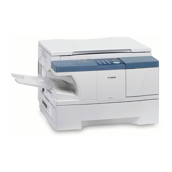
Summary of Contents for Canon iR1200 Series
- Page 1 Installation Procedure iR1200 Series iR1570F Jun 18 2004...
- Page 3 When changes occur in applicable products or in the contents of this manual, Canon will release technical information as the need arises. In the event of major changes in the contents of this manual over a long or short period, Canon will issue a new edition of this manual.
- Page 4 Introduction Symbols Used This documentation uses the following symbols to indicate special information: Symbol Description Indicates an item of a non-specific nature, possibly classified as Note, Caution, or Warning. Indicates an item requiring care to avoid electric shocks. Indicates an item requiring care to avoid combustion (fire). Indicates an item prohibiting disassembly to avoid electric shocks or problems.
- Page 5 Introduction The following rules apply throughout this Service Manual: 1. Each chapter contains sections explaining the purpose of specific functions and the relationship between electrical and mechanical systems with reference to the timing of operation. In the diagrams, represents the path of mechanical drive; where a signal name accompanies the symbol , the arrow indicates the direction of the electric signal.
-
Page 7: Table Of Contents
Contents Contents 第 1 章 Installation Procedure 1.1 Making Pre-Checks ............................... 2 1.1.1Selecting the Site ............................. 2 1.2 Unpacking and Installation............................ 3 1.2.1Before Starting ..............................3 1.2.2Installation Procedure............................3 1.2.3Unpacking ............................... 3 1.2.4Fitting the Cartridge ............................4 1.2.5Fitting the Toner bottle............................ 4 1.2.6Putting Paper in the Cassette ........................... - Page 8 Contents...
- Page 9 Chapter 1 Installation Procedure...
-
Page 10: Making Pre-Checks
Chapter 1 1.1 Making Pre-Checks 1.1.1 Selecting the Site 0006-2646 T-1-1 The site must meet the following requirements; if possible, visit the user's before the machine is delivered: The site must offer a power outlet whose rating is as specified volts (-/ +10%) and which may be used exclusively for the machine. -
Page 11: Unpacking And Installation
Chapter 1 Unpacking 1.2.3 Unpacking 0006-2670 Installation 1) Unpack the machine, and take out the attachments. Check to see that none of the following is missing: - cassette 1.2.1 Before Starting 0006-2663 - delivery tray - cartridge (durm unit and developing unit) Go through the following before starting to install the - power cord machine:... -
Page 12: 4Fitting The Cartridge
Chapter 1 F-1-2 6) Open the cartridge cover. F-1-5 3) Close the cartridge cover, and put back the reader unit. 1.2.5 Fitting the Toner bottle 0006-2713 1) Open the toner supply cover. F-1-3 7) Store away the securing member removed in step 4 in the shipping screw slot. -
Page 13: 6Putting Paper In The Cassette
Chapter 1 F-1-8 4) Holding the toner bottle steady with one hand, firmly and slowly pull the sealing tape tab with the Before Complete F-1-10 other hand to remove the sealing tape completely. Throw the tape away. To avoid breaking the tape, do not pull it at an angle. F-1-11 6) Close the toner supply cover. -
Page 14: 7Putting Paper In The Manual Feed Tray
Chapter 1 F-1-13 F-1-16 2) Put paper in the cassette, under the claw must 3) Place the paper (with the side to be copied onto indicate what [1] and [2] are. facing up). F-1-17 4) Adjust the slide guide to suit the width of the paper. F-1-14 3) Slide in the cassette until it stops. -
Page 15: 9Connect The Power Cord
Chapter 1 Use interface cables that comply with specifications of the machine. USB cable specifications: 5 m or shorter. Parallel interface cable specifications: 3 m or shorter (Compliant IEEE1284, bi-directional communication) F-1-21 1.2.11 Setting the Printer Functions 0006-2744 1) Install printer drivers, and perform test printing from the PC to check the images. -
Page 16: Connection To Telephone Line
Chapter 1 1.3 Connection to Telephone Line 1.3.1 Connecting the Modular Cable (if equipped with fax functions) 0006-2740 1) Connect one end of the modular cable to the terminal [L], and the other end to the socket of the telephone. If both telephone and fax are to be used, connect the modular cable from the telephone (or answering machine) to the [telephone] terminal. - Page 17 Chapter 1 2) Try sending and receiving an original and check the operation and the images.
-
Page 18: Checking The Images/Operations
Chapter 1 1.4 Checking the Images/Operations 1.4.1 Checking the Copy Images 0006-2743 1) Execute the following in user mode to stir toner: 6.ADJUST/CLEAN>4.MIX TONER. 2) Place an original on the copyboard glass or in the ADF and select the cassette or the manual feed tray as the source of paper;... -
Page 19: 第 2 章 Relocating The Machine
Chapter 2 Relocating the Machine... -
Page 20: When Relocating The Machine
2.1 When Relocating the Machine 0006-2950 If the machine must be moved by truck or other means of transportation, be sure to go through the following: 1. If the machine is equipped with fax function and the move will take 2 hours or more, the fax image data, if any, will be lost. - Page 21 Take full care to avoid severe vibration during the relocation.
- Page 23 Jun 18 2004...


Need help?
Do you have a question about the iR1200 Series and is the answer not in the manual?
Questions and answers