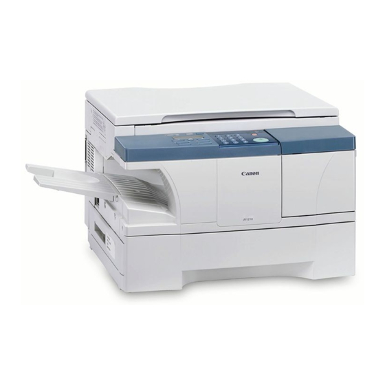
Canon iR1200 Series Service Manual

Canon iR1200 Series Service Manual

Hide thumbs Also See for iR1200 Series:
Table of Contents

Advertisement

iR1200/iR1300
Series
REVISION 0
FY8-13HU-000
AUG. 2002
COPYRIGHT © 2002 CANON INC.
2000 2000 2000 2000
CANON iR1200/iR1300 Series REV. 0 AUG. 2002

Advertisement

Table of Contents
loading

Summary of Contents for Canon iR1200 Series

  • Page 1 Series REVISION 0 FY8-13HU-000 AUG. 2002 COPYRIGHT © 2002 CANON INC. 2000 2000 2000 2000 CANON iR1200/iR1300 Series REV. 0 AUG. 2002...
  • Page 2 Application This manual has been issued by Canon Inc. for qualified persons to learn technical theory, installation, maintenance, and repair of products. This manual covers all localities where the products are sold. For this reason, there may be information in this manual that does not apply to your locality.
  • Page 3 Provides a description of a service mode. Provides a description of the nature of an error indication. Refers to the Copier Basics Series for a better understanding of the contents. COPYRIGHT © 2002 CANON INC. 2000 2000 2000 2000 CANON iR1200/iR1300 Series REV. 0 AUG. 2002...
  • Page 4 INTRODUCTION 2 Outline of the Manual This Service Manual provides basic facts and figures needed to service the iR1200 Series/ iR1300 Series products in the field, and it consists of the following chapters: Chapter 1 Product Outline: specifications, names of parts, safety and warnings...
  • Page 5 (as by being able to identify possible causes of problems). COPYRIGHT © 2002 CANON INC. 2000 2000 2000 2000 CANON iR1200/iR1300 Series REV. 0 AUG. 2002...
  • Page 6 500 sheet (LTR/LGL) 3R2E √ √ √ 120V iR1370F 500 sheet (LTR/LGL) 3R2E The notation “ √” indicates that the item in question is available. COPYRIGHT © 2002 CANON INC. 2000 2000 2000 2000 CANON iR1200/iR1300 Series REV. 0 AUG. 2002...
  • Page 7: Table Of Contents

    3.6 Numeric Parameter Setting fax functions) ..... 2-19 (#3 NUMERIC Param.) ... 2-50 2.2.2.1 Memory Clear List ..2-20 3.7 SPECIAL Setting (#4A SPECIAL) ....... 2-55 COPYRIGHT © 2002 CANON INC. 2000 2000 2000 2000 CANON iR1200/1300 Series REV. 0 AUG. 2002...
  • Page 8 2.7 Putting Paper in the Manual 2.2 Installation Procedure ....3-2 Feed Tray ........3-9 2.3 Unpacking ........3-3 2.8 Connecting the Interface Cable ..........3-10 COPYRIGHT © 2002 CANON INC. 2000 2000 2000 2000 CANON iR1200/1300 Series REV. 0 AUG. 2002...
  • Page 9 3.1 Outline ........4-14 Bias ........4-29 4 Image Formation System ....4-16 6.2.3 Fixing Heater Safety 4.1 Outline ........4-16 Mechanism ......4-29 COPYRIGHT © 2002 CANON INC. 2000 2000 2000 2000 CANON iR1200/1300 Series REV. 0 AUG. 2002...
  • Page 10 Removing the Analog Cover ......5-9 Processor PCB ....5-23 2.1.1.9 Removing the Right 2.2.3 Removing the Sensor Door ......5-11 PCB ........5-25 viii COPYRIGHT © 2002 CANON INC. 2000 2000 2000 2000 CANON iR1200/1300 Series REV. 0 AUG. 2002...
  • Page 11 Tray Paper Sensor ....5-50 Stacking Tray/Original 2.6.8 Removing the Vertical Path Delivery Roller ..... 5-75 Roller ......... 5-51 2.8.4.2 Removing the Original Delivery Sensor .... 5-76 COPYRIGHT © 2002 CANON INC. 2000 2000 2000 2000 CANON iR1200/1300 Series REV. 0 AUG. 2002...
  • Page 12 Intensity Auto Adjustment ....7-12 Adjustment ..... 7-5 1.3.4.2 Original Read Position 1.2.4.2 Leading Edge Read Start Adjustment ....7-12 Position Adjustment ..7-6 COPYRIGHT © 2002 CANON INC. 2000 2000 2000 2000 CANON iR1200/1300 Series REV. 0 AUG. 2002...
  • Page 13 4.2.10 The message “PLATEN/COVER (vertical)......7-28 3.1.10 The output has white lines IS OPEN CLOSE PLATEN/ (vertical)......7-28 COVER” fails to go OFF. .. 7-47 COPYRIGHT © 2002 CANON INC. 2000 2000 2000 2000 CANON iR1200/1300 Series REV. 0 AUG. 2002...
  • Page 14 6.2.1.1 Body ......7-101 6.2.1.2 ADF (if equipped with #1 SSSW ....... 7-54 4.5.3.10 Subaddress ....7-55 ADF functions) ... 7-102 4.5.3.11 Password ....... 7-55 COPYRIGHT © 2002 CANON INC. 2000 2000 2000 2000 CANON iR1200/1300 Series REV. 0 AUG. 2002...
  • Page 15 1 General Timing Chart ......A-1 3 List of Special Tools ......A-5 2 General Circuit Diagram ....A-3 4 List of Solvents and Oils ....A-6 xiii COPYRIGHT © 2002 CANON INC. 2000 2000 2000 2000 CANON iR1200/1300 Series REV. 0 AUG. 2002...
  • Page 17: Chapter 1 Product Outline

    CHAPTER 1 PRODUCT OUTLINE COPYRIGHT © 2002 CANON INC. 2000 2000 2000 2000 CANON iR1200/iR1300 Series REV. 0 AUG. 2002...
  • Page 19: Specifications

    Dry, 1-component toner projection Pickup Cassette: 1 cassette Multifeeder: 1 feeder Transfer Roller transfer Separate Static (static eliminator) + curvature Cleaning Rubber blade Fixing SURF (on-demand) COPYRIGHT © 2002 CANON INC. 2000 2000 2000 2000 CANON iR1200/iR1300 Series REV. 0 AUG. 2002...
  • Page 20: Functions

    Delivery tray capacity 100 sheets max. Non-image width Leading edge: 3.0 ± 2.0 mm (0.12" ± 0.08"), left/right edge: 2.5 ± 2.0 mm (0.10" ± 0.08") COPYRIGHT © 2002 CANON INC. 2000 2000 2000 2000 CANON iR1200/iR1300 Series REV. 0 AUG. 2002...
  • Page 21 In the case of fax, select “Print” or “Remain the image data in the memory” at the user mode display in advance. Follow the action selected at the user mode. COPYRIGHT © 2002 CANON INC. 2000 2000 2000 2000 CANON iR1200/iR1300 Series REV. 0 AUG. 2002...
  • Page 22: Others

    Paper Keep wrapped to avoid humidity. Toner Avoid direct sunshine, and store between 0° and 35°C / 32° and 95°F, between 35% and 85%. COPYRIGHT © 2002 CANON INC. 2000 2000 2000 2000 CANON iR1200/iR1300 Series REV. 0 AUG. 2002...
  • Page 23: Reproduction Ratio

    Enlarge II 1 : 1.294 Enlarge III 1 : 1.414 1 : 1.414 Enlarge IV 1 : 2.000 1 : 2.000 1 : 2.000 COPYRIGHT © 2002 CANON INC. 2000 2000 2000 2000 CANON iR1200/iR1300 Series REV. 0 AUG. 2002...
  • Page 24: Copying Speed (Ab Type, A Type)

    (See 5.4 of Chapter 4.) COPYRIGHT © 2002 CANON INC. 2000 2000 2000 2000 CANON iR1200/iR1300 Series REV. 0 AUG. 2002...
  • Page 25 (See 5.4 of Chapter 4.) COPYRIGHT © 2002 CANON INC. 2000 2000 2000 2000 CANON iR1200/iR1300 Series REV. 0 AUG. 2002...
  • Page 26: Adf (If Equipped With Adf Functions)

    Advise the user to remove as much curling as possible, if any, and place the original in the original tray so that the side with the curling is the trailing edge. COPYRIGHT © 2002 CANON INC. 2000 2000 2000 2000 CANON iR1200/iR1300 Series REV. 0 AUG. 2002...
  • Page 27: Fax (If Equipped Fax Functions)

    Canon express protocol None Transmission output level from 0 to -15 dBm Minimum receive input level -43 dBm (at. V.17) Modem IC CONEXANT FM336 COPYRIGHT © 2002 CANON INC. 2000 2000 2000 2000 CANON iR1200/iR1300 Series REV. 0 AUG. 2002...
  • Page 28: Scanner Section Specifications

    64-gradation error diffusion system 1.8.3 Printer section specifications Printing resolution 600dpi × 600dpi Reduction for reception Fixed reduction (75%, 90%, 95%, 97%) Auto reduction (70~100%) 1-10 COPYRIGHT © 2002 CANON INC. 2000 2000 2000 2000 CANON iR1200/iR1300 Series REV. 0 AUG. 2002...
  • Page 29: Functions

    Confidential transmission None Remote reception Method ID call# (ID input method) Remote ID (with ID call#) 2 digits (Default : 25) Memory reception 1-11 COPYRIGHT © 2002 CANON INC. 2000 2000 2000 2000 CANON iR1200/iR1300 Series REV. 0 AUG. 2002...
  • Page 30 Relay broadcasting originating None Relay broadcasting None Closed network None Direct mail prevention None Dual access File No. of reservation Max. 21 files 1-12 COPYRIGHT © 2002 CANON INC. 2000 2000 2000 2000 CANON iR1200/iR1300 Series REV. 0 AUG. 2002...
  • Page 31 Backup IC 128 Kbyte SRAM Backup battery Lithium battery 3.0 V DC / 560 mAh Battery life Approx. 5 years 1-13 COPYRIGHT © 2002 CANON INC. 2000 2000 2000 2000 CANON iR1200/iR1300 Series REV. 0 AUG. 2002...
  • Page 32 40 cycles with 100% discharge (Temperature 77°F (25°C)) Time precision ±60 sec per month The foregoing specifications are subject to change for product improvement. 1-14 COPYRIGHT © 2002 CANON INC. 2000 2000 2000 2000 CANON iR1200/iR1300 Series REV. 0 AUG. 2002...
  • Page 33: Names Of Parts

    [6] Manual feed tray [13] USB cable connector assembly [7] Toner supply cover [14] Parallel interface cable connector assembly *1: If equipped with fax functions. 1-15 COPYRIGHT © 2002 CANON INC. 2000 2000 2000 2000 CANON iR1200/iR1300 Series REV. 0 AUG. 2002...
  • Page 34: Body (Copyboard Type)

    [10] Power cord connector assembly [5] Manual feed tray [11] USB cable connector assembly [6] Toner supply cover [12] Parallel interface cable connector assembly 1-16 COPYRIGHT © 2002 CANON INC. 2000 2000 2000 2000 CANON iR1200/iR1300 Series REV. 0 AUG. 2002...
  • Page 35 CHAPTER 1 PRODUCT OUTLINE F01-201-03 [1] Drum shutter stopper [4] Right door [2] Cartridge cover [5] Shipping screw slot [3] Cartridge 1-17 COPYRIGHT © 2002 CANON INC. 2000 2000 2000 2000 CANON iR1200/iR1300 Series REV. 0 AUG. 2002...
  • Page 36 CHAPTER 1 PRODUCT OUTLINE 2.1.3 ADF (if equipped with ADF functions) F01-201-04 [1] Original placement area [3] Delivery slot [2] Open/close cover [4] Slide guide 1-18 COPYRIGHT © 2002 CANON INC. 2000 2000 2000 2000 CANON iR1200/iR1300 Series REV. 0 AUG. 2002...
  • Page 37 [9] Manual feed pickup roller [21] Delivery roller [10] Manual feed tray [22] Cassette [11] Right door [23] Delivery tray [12] Vertical path roller 1-19 COPYRIGHT © 2002 CANON INC. 2000 2000 2000 2000 CANON iR1200/iR1300 Series REV. 0 AUG. 2002...
  • Page 38 [9] Original feed roller [10] Contact sensor (body) [11] White roller [12] ADF registration roller [13] Registration sensor [14] Original separation pad [15] Original sensor 1-20 COPYRIGHT © 2002 CANON INC. 2000 2000 2000 2000 CANON iR1200/iR1300 Series REV. 0 AUG. 2002...
  • Page 39 US. F01-301-01 The text may differ from product to product or from model to model. 1-21 COPYRIGHT © 2002 CANON INC. 2000 2000 2000 2000 CANON iR1200/iR1300 Series REV. 0 AUG. 2002...
  • Page 40 The laser scanner unit of this model cannot be adjusted in the field. F01-301-02 The label is attached to covers inside the machine used to block out laser radiation. 1-22 COPYRIGHT © 2002 CANON INC. 2000 2000 2000 2000 CANON iR1200/iR1300 Series REV. 0 AUG. 2002...
  • Page 41 01, and keep the following in mind: • Avoid direct sunshine. • Avoid vibration. • Avoid impact. (Take care not to drop it.) 1-23 COPYRIGHT © 2002 CANON INC. 2000 2000 2000 2000 CANON iR1200/iR1300 Series REV. 0 AUG. 2002...
  • Page 42 Avoid areas exposed to corrosive gas (e.g., insecticide) or salty air. e. Avoid areas subject to dust, ammonium gas, or organic solvent gas. 1-24 COPYRIGHT © 2002 CANON INC. 2000 2000 2000 2000 CANON iR1200/iR1300 Series REV. 0 AUG. 2002...
  • Page 43 Do not place the cartridge on its end or upside down as shown in F01-303-01. Also, do not swing it. F01-303-01 c. Do not touch the surface of the drum unit. F01-303-02 1-25 COPYRIGHT © 2002 CANON INC. 2000 2000 2000 2000 CANON iR1200/iR1300 Series REV. 0 AUG. 2002...
  • Page 44 5 min in a dark place, it may recover to a level that will not cause practical problems. Nevertheless, avoid direct sunshine by all Memo means, which is as strong as 10000 to 30000 lux. 1-26 COPYRIGHT © 2002 CANON INC. 2000 2000 2000 2000 CANON iR1200/iR1300 Series REV. 0 AUG. 2002...
  • Page 45 Be sure to use the drum shutter stopper as replacing the drum unit. m. Use the packaging box of the new drum unit if available. 1-27 COPYRIGHT © 2002 CANON INC. 2000 2000 2000 2000 CANON iR1200/iR1300 Series REV. 0 AUG. 2002...
  • Page 47: Chapter 2 Using The Machine

    CHAPTER 2 USING THE MACHINE COPYRIGHT © 2002 CANON INC. 2000 2000 2000 2000 CANON iR1200/iR1300 Series REV. 0 AUG. 2002...
  • Page 49: Control Panel

    Press it when using a fax function. The key remains ON when the machine is in fax mode. *1: If equipped with fax functions. COPYRIGHT © 2002 CANON INC. 2000 2000 2000 2000 CANON iR1200/iR1300 Series REV. 0 AUG. 2002...
  • Page 50 Press it to dial a pre-registered telephone number. A press on the Function key will cause it to serve as the Fax Function key. *1: If equipped with fax functions. *2: Only for the iR1310/1330/1370F models. COPYRIGHT © 2002 CANON INC. 2000 2000 2000 2000 CANON iR1200/iR1300 Series REV. 0 AUG. 2002...
  • Page 51 Pause key. *1: If equipped with fax functions; or only when the Function key is ON. *2: If equipped with fax functions. COPYRIGHT © 2002 CANON INC. 2000 2000 2000 2000 CANON iR1200/iR1300 Series REV. 0 AUG. 2002...
  • Page 52 *1: If equipped with fax functions. *2: If equipped with fax functions; or only when the Function key is ON. *3: Only for the iR1370F model. COPYRIGHT © 2002 CANON INC. 2000 2000 2000 2000 CANON iR1200/iR1300 Series REV. 0 AUG. 2002...
  • Page 53: User Mode

    3.TX DONE TONE VOLUME1~3 (1) ERROR ONLY VOLUME1~3 (1) 4.RX DONE TONE VOLUME1~3 (1) ERROR ONLY VOLUME1~3 (1) *1: Only if equipped with fax functions. COPYRIGHT © 2002 CANON INC. 2000 2000 2000 2000 CANON iR1200/iR1300 Series REV. 0 AUG. 2002...
  • Page 54 1.VERTICAL SIZE 76~216mm (216) 2.HORIZONTAL SIZE 127~356mm (356) *1: Only if equipped with fax functions. *2: Factory default for A/AB area. *3: Factory default for Inch area. COPYRIGHT © 2002 CANON INC. 2000 2000 2000 2000 CANON iR1200/iR1300 Series REV. 0 AUG. 2002...
  • Page 55 *1: Factory default for A/AB area. *2: Factory default for Inch area. *3: This setting may be unavailable depending on the value set for service mode #5 TYPE. COPYRIGHT © 2002 CANON INC. 2000 2000 2000 2000 CANON iR1200/iR1300 Series REV. 0 AUG. 2002...
  • Page 56 *1: Factory default for A/AB area. *2: Factory default for Inch area. *3: Factory default for A area. *4: Factory default for AB area. COPYRIGHT © 2002 CANON INC. 2000 2000 2000 2000 CANON iR1200/iR1300 Series REV. 0 AUG. 2002...
  • Page 57 33600bps 14400bps 9600bps 7200bps 4800bps 2400bps 4.RX START SPEED 33600bps 14400bps 9600bps 7200bps 4800bps 2400bps 2.UNIT NAME *1: Only if equipped with fax functions. COPYRIGHT © 2002 CANON INC. 2000 2000 2000 2000 CANON iR1200/iR1300 Series REV. 0 AUG. 2002...
  • Page 58 7.R-KEY SETTING* PSTN HOOKING EARTH CONNECTION PREFIX *1:Only if equipped with fax functions. *2:Only if equipped with fax functions and a 230V model. 2-10 COPYRIGHT © 2002 CANON INC. 2000 2000 2000 2000 CANON iR1200/iR1300 Series REV. 0 AUG. 2002...
  • Page 59 2.REDIAL INTERBAL 02~99MIN. (02) 3.TX ERROR RESEND RESEND TX FROM ERROR & 1ST PG ERROR PAGE ALL PAGES *1:Only if equipped with fax functions 2-11 COPYRIGHT © 2002 CANON INC. 2000 2000 2000 2000 CANON iR1200/iR1300 Series REV. 0 AUG. 2002...
  • Page 60 F/T RING TIME 01~99SEC (15) 6.REMOTE RX REMOTE RX ID 00~99 (25) *1: Only if equipped with fax functions. *2: Only for the iR1370F model. 2-12 COPYRIGHT © 2002 CANON INC. 2000 2000 2000 2000 CANON iR1200/iR1300 Series REV. 0 AUG. 2002...
  • Page 61 *1: Only if equipped with fax functions. *2: This setting may be unavailable depending on the valve set for service mode #1 SSSW>SW-14>bit 0,1. 2-13 COPYRIGHT © 2002 CANON INC. 2000 2000 2000 2000 CANON iR1200/iR1300 Series REV. 0 AUG. 2002...
  • Page 62 *1: Only if equipped with fax functions. *2: This setting may be unavailable depending on the value set for service mode #5 TYPE. 2-14 COPYRIGHT © 2002 CANON INC. 2000 2000 2000 2000 CANON iR1200/iR1300 Series REV. 0 AUG. 2002...
  • Page 63 POLLING RX 1. PASSWORD 2. SUBADDRESS 3.GROUP DIAL 01~12 1.TEL NUMBER ENTRY 2.NAME 3.TX TIME SETTING *1: Only if equipped with fax functions. 2-15 COPYRIGHT © 2002 CANON INC. 2000 2000 2000 2000 CANON iR1200/iR1300 Series REV. 0 AUG. 2002...
  • Page 64 YYYY MM/DD MM/DD YYYY DD/MM YYYY 6.ADJUST./CLEAN 1.ROLLER CLEANING 2.CLEAN ADF ROLLER 3.RESTART PRINTER 4.MIX TONER *1: Only if equipped with ADF functions. 2-16 COPYRIGHT © 2002 CANON INC. 2000 2000 2000 2000 CANON iR1200/iR1300 Series REV. 0 AUG. 2002...
  • Page 65 *3: The specifics indicated by the Count Check menu may be selected in service mode (#3 NUMERIC PARAM; No. 57 through 61; see 3.6 of Chapter 2). 2-17 COPYRIGHT © 2002 CANON INC. 2000 2000 2000 2000 CANON iR1200/iR1300 Series REV. 0 AUG. 2002...
  • Page 66: User Report

    Use the Left or Right Arrow key to select a list to print, then press OK key. *1: Only if equipped with fax functions. T02-202-01 2-18 COPYRIGHT © 2002 CANON INC. 2000 2000 2000 2000 CANON iR1200/iR1300 Series REV. 0 AUG. 2002...
  • Page 67: Automatically Generating Reports (If Equipped With Fax Functions)

    (BAT2) will be- come exhausted. A report will automatically be generated when the machine is turned on. T02-202-02 2-19 COPYRIGHT © 2002 CANON INC. 2000 2000 2000 2000 CANON iR1200/iR1300 Series REV. 0 AUG. 2002...
  • Page 68: Memory Clear List

    PGS. : number of pages stored SET TIME : date/time (in 24-hr notation) ST. TIME : start of storage (in 24-hr notation) 2-20 COPYRIGHT © 2002 CANON INC. 2000 2000 2000 2000 CANON iR1200/iR1300 Series REV. 0 AUG. 2002...
  • Page 69: Service Mode

    Or, settings may also be made for humidity sensor fixed mode. PDL: not used COUNTER: counter information Use it to check various counter information. 2-21 COPYRIGHT © 2002 CANON INC. 2000 2000 2000 2000 CANON iR1200/iR1300 Series REV. 0 AUG. 2002...
  • Page 70 Use it to indicate information related to the ROM on the LCD (e.g., ROM version, checksum). #14 CS SET: not used TEST MODE: Use it to execute various testings. 2-22 COPYRIGHT © 2002 CANON INC. 2000 2000 2000 2000 CANON iR1200/iR1300 Series REV. 0 AUG. 2002...
  • Page 71: Using Service Mode

    Press the Left or Right Arrow key. NUMER I C P a r am. 0 0 2 7) Press the Stop key/Additional Functions key to end service mode. F02-302-01 2-23 COPYRIGHT © 2002 CANON INC. 2000 2000 2000 2000 CANON iR1200/iR1300 Series REV. 0 AUG. 2002...
  • Page 72: List Of Service Mode Menus

    Do not change the following, reserved for the future; SW7 through 11, 13, 15 through 24, 27, 29 through 32, 34 through 50. 2-24 COPYRIGHT © 2002 CANON INC. 2000 2000 2000 2000 CANON iR1200/iR1300 Series REV. 0 AUG. 2002...
  • Page 73 11 through 20: not used 020: F02-303-02 Do not change the following, reserved for the future: No. 01 through 04, 11 through 20. 2-25 COPYRIGHT © 2002 CANON INC. 2000 2000 2000 2000 CANON iR1200/iR1300 Series REV. 0 AUG. 2002...
  • Page 74 058: (0~999) no indication 059: (0~999) no indication 060: (0~999) no indication 061: (0~999) no indication 062: not used 080: not used F02-303-03 2-26 COPYRIGHT © 2002 CANON INC. 2000 2000 2000 2000 CANON iR1200/iR1300 Series REV. 0 AUG. 2002...
  • Page 75 The settings under this item are collectively and automatically set in conjunction with #5 TYPE to suit the communications standards of a specific country/region. Not used. (Do not change the setting.) 2-27 COPYRIGHT © 2002 CANON INC. 2000 2000 2000 2000 CANON iR1200/iR1300 Series REV. 0 AUG. 2002...
  • Page 76 #4 will comply with the communications standards of the selected country/region. When changing the TYPE setting, be sure not to select a country/region which is not the country/region of installation. 2-28 COPYRIGHT © 2002 CANON INC. 2000 2000 2000 2000 CANON iR1200/iR1300 Series REV. 0 AUG. 2002...
  • Page 77 #1 SSSW: SW01 through 05, 07 through 12, 14 though 20. Also, do not change the setting of ‘#2 NUMBER Param’. 2-29 COPYRIGHT © 2002 CANON INC. 2000 2000 2000 2000 CANON iR1200/iR1300 Series REV. 0 AUG. 2002...
  • Page 78 MISC not used F02-303-06 #8 PDL Not used. 2-30 COPYRIGHT © 2002 CANON INC. 2000 2000 2000 2000 CANON iR1200/iR1300 Series REV. 0 AUG. 2002...
  • Page 79 PCB ROM version indication #14 CS SET TEST MODE [1] ~ [6], [8] F02-303-07 #11 DOWNLOAD Not used. #14 CS SET Not used. 2-31 COPYRIGHT © 2002 CANON INC. 2000 2000 2000 2000 CANON iR1200/iR1300 Series REV. 0 AUG. 2002...
  • Page 80: Bit Switch Settings (#1 Sssw)

    If set to ‘1’, on the other hand, all items may be set by the user, regardless of the country setting. 2-32 COPYRIGHT © 2002 CANON INC. 2000 2000 2000 2000 CANON iR1200/iR1300 Series REV. 0 AUG. 2002...
  • Page 81 If an error (e.g., jam) occurs during output, the machine goes back to 1. above. If set to ‘0’, on the other hand, the machine will sound the alarm and enters standby state. 2-33 COPYRIGHT © 2002 CANON INC. 2000 2000 2000 2000 CANON iR1200/iR1300 Series REV. 0 AUG. 2002...
  • Page 82 CED signal. Set it to ‘1’ if an error occurs often because of an error at time of reception. The following error codes are associated with an echo at time of reception: ##005, ##101, ##106, ##107, ##114, ##200, ##201, ##790 Memo 2-34 COPYRIGHT © 2002 CANON INC. 2000 2000 2000 2000 CANON iR1200/iR1300 Series REV. 0 AUG. 2002...
  • Page 83 Long distance (2) sends an 1850-Hz tonal signal when the DIS signal is transmitted. Long distance (3) sends a 1650-Hz tonal signal when the DIS signal is transmitted. 2-35 COPYRIGHT © 2002 CANON INC. 2000 2000 2000 2000 CANON iR1200/iR1300 Series REV. 0 AUG. 2002...
  • Page 84 If an error occurs often because of the line condition at time of reception, set it to ‘1’ and, at the same time, set ‘ECM RX’ to ‘OFF’ for user data. 2-36 COPYRIGHT © 2002 CANON INC. 2000 2000 2000 2000 CANON iR1200/iR1300 Series REV. 0 AUG. 2002...
  • Page 85 Use it to specify whether or not to send the CED signal at time of manual reception. Set it to ‘transmit’ if the other party does not start transmission when manual reception is initiated. 2-37 COPYRIGHT © 2002 CANON INC. 2000 2000 2000 2000 CANON iR1200/iR1300 Series REV. 0 AUG. 2002...
  • Page 86 [Bit 3] Use it specify whether or not to transmit bit 33 and thereafter for the DIS signal. If ‘prohibit’ is selected, Super Fine reception from a non-Canon machine can no longer be used. 2-38 COPYRIGHT © 2002 CANON INC.
  • Page 87 Use it to select a read width for originals. If ‘LTR’ is selected, the machine will read LTR originals at LTR width (212 mm). 2-39 COPYRIGHT © 2002 CANON INC. 2000 2000 2000 2000 CANON iR1200/iR1300 Series REV. 0 AUG. 2002...
  • Page 88 32 min or more. To set a time-out length, refer to the next page. If ‘1’ is selected for bit 7, the 1-page time-out length will be as set by bit 0 and bit 1. 2-40 COPYRIGHT © 2002 CANON INC. 2000 2000 2000 2000 CANON iR1200/iR1300 Series REV. 0 AUG. 2002...
  • Page 89 8 min 16 min 32 min 64 min Time-Out Length for Reception time-out length 8 min 16 min 32 min 64 min 2-41 COPYRIGHT © 2002 CANON INC. 2000 2000 2000 2000 CANON iR1200/iR1300 Series REV. 0 AUG. 2002...
  • Page 90 1 and 2 of SW05 and bit Memo 2 of SW14 of #1 SSSW as well as the type of dialing used. 2-42 COPYRIGHT © 2002 CANON INC. 2000 2000 2000 2000 CANON iR1200/iR1300 Series REV. 0 AUG. 2002...
  • Page 91 2-43 COPYRIGHT © 2002 CANON INC. 2000 2000 2000 2000 CANON iR1200/iR1300 Series REV. 0 AUG. 2002...
  • Page 92 (CSI signal data) will be Memo indicated on the report even when ‘number of caller’ is selected. 2-44 COPYRIGHT © 2002 CANON INC. 2000 2000 2000 2000 CANON iR1200/iR1300 Series REV. 0 AUG. 2002...
  • Page 93 Use it to specify whether or not to generate an error TX report when a transmission is sus- pended by pressing the Stop key. 2-45 COPYRIGHT © 2002 CANON INC. 2000 2000 2000 2000 CANON iR1200/iR1300 Series REV. 0 AUG. 2002...
  • Page 94 [Bit 5] Select whether the transmitter falls beck during V.34 transmission. If “Prohibit” is selected, the transmitter does not fall back. 2-46 COPYRIGHT © 2002 CANON INC. 2000 2000 2000 2000 CANON iR1200/iR1300 Series REV. 0 AUG. 2002...
  • Page 95 If ‘yes’ is selected, the serial No. will be indicated. If ‘no’ is selected, on the other hand, the serial No. will not be indicated. 2-47 COPYRIGHT © 2002 CANON INC. 2000 2000 2000 2000 CANON iR1200/iR1300 Series REV. 0 AUG. 2002...
  • Page 96: Menu Switch Settings (#2 Menu)

    SERVICEMAN [2]: not used OFF: Select it to mute the monitor sound for the telephone line for the speaker. 2-48 COPYRIGHT © 2002 CANON INC. 2000 2000 2000 2000 CANON iR1200/iR1300 Series REV. 0 AUG. 2002...
  • Page 97 At times, certain types of external telephones fail to ring while fax/tel switch-over takes place. If so, change the frequency of the pseudo CI signal. 2-49 COPYRIGHT © 2002 CANON INC. 2000 2000 2000 2000 CANON iR1200/iR1300 Series REV. 0 AUG. 2002...
  • Page 98: Numeric Parameter Setting (#3 Numeric Param.)

    0 to 999 count type select 4 0 to 999 count type select 5 0 to 999 count type select 6 0 to 999 2-50 COPYRIGHT © 2002 CANON INC. 2000 2000 2000 2000 CANON iR1200/iR1300 Series REV. 0 AUG. 2002...
  • Page 99 Use it to set the length of time for line connection identification. If an error occurs often because of the line condition at time of a communication, increase the parameter. 2-51 COPYRIGHT © 2002 CANON INC. 2000 2000 2000 2000 CANON iR1200/iR1300 Series REV. 0 AUG. 2002...
  • Page 100 V.21 low-speed command preamble is detected continuously for a specific period of time.) [No. 28] Use it to set the length of time during which the Menu Select screen is indicated on the LCD. 2-52 COPYRIGHT © 2002 CANON INC. 2000 2000 2000 2000 CANON iR1200/iR1300 Series REV. 0 AUG. 2002...
  • Page 101 703 : not used 704 : not used 801 : report print 802 : not used 803 : not used 804 : not used 2-53 COPYRIGHT © 2002 CANON INC. 2000 2000 2000 2000 CANON iR1200/iR1300 Series REV. 0 AUG. 2002...
  • Page 102 1 301 √ total 1 331 received print √ total 1 701 report print √ total 1 801 √ scan total 1 505 2-54 COPYRIGHT © 2002 CANON INC. 2000 2000 2000 2000 CANON iR1200/iR1300 Series REV. 0 AUG. 2002...
  • Page 103: Special Setting (#4A Special)

    When a country/region is selected for the indicated list, the data under #4 NCU will be set to suit the communication standards of the county/region. Be sure not to select a different country/region from the country/region of installation. 2-55 COPYRIGHT © 2002 CANON INC. 2000 2000 2000 2000 CANON iR1200/iR1300 Series REV. 0 AUG. 2002...
  • Page 104: Setting The Original Reading Functions (#6 Scanner)

    The factory settings of these adjustments differ from machine to machine. For instructions on adjustment, see 1.2.4 of Chapter 7 or 1.3.4 of Chapter 7. 2-56 COPYRIGHT © 2002 CANON INC. 2000 2000 2000 2000 CANON iR1200/iR1300 Series REV. 0 AUG. 2002...
  • Page 105: Setting The Printer Parameters (#7 Printer)

    For instance, if an extra-length original as long as 2.5 A4R originals is received, it will be reduced to 70% to print on 2 A4R sheets. 2-57 COPYRIGHT © 2002 CANON INC. 2000 2000 2000 2000 CANON iR1200/iR1300 Series REV. 0 AUG. 2002...
  • Page 106 H/H mode: use it if the environment is H/H, and the site of installation is sub- ject to an extremely low level of temperature/humidity. 2-58 COPYRIGHT © 2002 CANON INC. 2000 2000 2000 2000 CANON iR1200/iR1300 Series REV. 0 AUG. 2002...
  • Page 107: Numeric Param

    Use it to reset the printer; or, use it to clear service error ‘E000’. 3.12.5 #5 MLT CLEANING Not used. 3.13 PDL (#8 PDL) Not used. 2-59 COPYRIGHT © 2002 CANON INC. 2000 2000 2000 2000 CANON iR1200/iR1300 Series REV. 0 AUG. 2002...
  • Page 108: Counter (#9 Counter)

    MISC not used *1: Not incremented at time of printing from the PC. 2-60 COPYRIGHT © 2002 CANON INC. 2000 2000 2000 2000 CANON iR1200/iR1300 Series REV. 0 AUG. 2002...
  • Page 109: Clearing The Counter Readings

    COUNTER REPORT counter readings PRINT SPEC REPORT TYPE setting, printing speed, memory size, ROM indication, ad- justment data 3.16 Downloading (#11 DOWNLOAD) Not used. 2-61 COPYRIGHT © 2002 CANON INC. 2000 2000 2000 2000 CANON iR1200/iR1300 Series REV. 0 AUG. 2002...
  • Page 110: Clearing (#12 Clear)

    Use it to indicate the version of the ROM on the printer controller PCB. 3.19 Resetting the Contact Sensor Position (#14 CS SET) Not used. 2-62 COPYRIGHT © 2002 CANON INC. 2000 2000 2000 2000 CANON iR1200/iR1300 Series REV. 0 AUG. 2002...
  • Page 111: Service Mode Default Setting

    DIAL DIAL 3429 3429 3429 3429 3429 3429 3429 33.6 33.6 33.6 33.6 33.6 33.6 33.6 25Hz 25Hz 25Hz 25Hz 25Hz 25Hz 25Hz 2-63 COPYRIGHT © 2002 CANON INC. 2000 2000 2000 2000 CANON iR1200/iR1300 Series REV. 0 AUG. 2002...
  • Page 112 DIAL DIAL 3429 3429 3429 3429 3429 3429 3429 33.6 33.6 33.6 33.6 33.6 33.6 33.6 25Hz 25Hz 25Hz 25Hz 25Hz 25Hz 25Hz 2-64 COPYRIGHT © 2002 CANON INC. 2000 2000 2000 2000 CANON iR1200/iR1300 Series REV. 0 AUG. 2002...
  • Page 113 DIAL DIAL 3429 3429 3429 3429 3429 3429 3429 33.6 33.6 33.6 33.6 33.6 33.6 33.6 25Hz 25Hz 25Hz 25Hz 25Hz 25Hz 25Hz 2-65 COPYRIGHT © 2002 CANON INC. 2000 2000 2000 2000 CANON iR1200/iR1300 Series REV. 0 AUG. 2002...
  • Page 114 DIAL DIAL 3429 3429 3429 3429 3429 3429 3429 33.6 33.6 33.6 33.6 33.6 33.6 33.6 25Hz 25Hz 25Hz 25Hz 25Hz 25Hz 25Hz 2-66 COPYRIGHT © 2002 CANON INC. 2000 2000 2000 2000 CANON iR1200/iR1300 Series REV. 0 AUG. 2002...
  • Page 115 3429 3429 not used not used 3429 33.6 33.6 not used not used 33.6 25Hz 25Hz not used not used 25Hz 2-67 COPYRIGHT © 2002 CANON INC. 2000 2000 2000 2000 CANON iR1200/iR1300 Series REV. 0 AUG. 2002...
  • Page 116 3500 3500 3500 3500 3500 3500 3500 1300 1300 1300 1300 1300 1300 1300 #5 TYPE EUROPE U.K. SWEDEN SWISS AUSTRIA DENMARK NORWAY 2-68 COPYRIGHT © 2002 CANON INC. 2000 2000 2000 2000 CANON iR1200/iR1300 Series REV. 0 AUG. 2002...
  • Page 117 3500 3500 3500 3500 3500 3500 3500 1300 1300 1300 1300 1300 1300 1300 #5 TYPE HOLLAND BELGUIM AUSTRALIA FINLAND N.Z. ITALY SPAIN 2-69 COPYRIGHT © 2002 CANON INC. 2000 2000 2000 2000 CANON iR1200/iR1300 Series REV. 0 AUG. 2002...
  • Page 118 3500 3500 3500 3500 3500 3500 3500 1300 1300 1300 1300 1300 1300 1310 #5 TYPE PORTUGAL IRELAND HONG KONG MALAYSIA HUNGARY KOREA 2-70 COPYRIGHT © 2002 CANON INC. 2000 2000 2000 2000 CANON iR1200/iR1300 Series REV. 0 AUG. 2002...
  • Page 119 3500 3500 3500 3500 3500 3500 3500 1300 1300 1300 1300 1300 1300 1300 #5 TYPE CHINA GERMAN FRANCE SINGAPORE CZECH SLOVENIA ASIA 2-71 COPYRIGHT © 2002 CANON INC. 2000 2000 2000 2000 CANON iR1200/iR1300 Series REV. 0 AUG. 2002...
  • Page 120 #5 TYPE POLAND EUROPE2 TAIWAN STANDARD 2-72 COPYRIGHT © 2002 CANON INC. 2000 2000 2000 2000 CANON iR1200/iR1300 Series REV. 0 AUG. 2002...
  • Page 121: Test Mode (Test Mode)

    Use it to check the operation of microswitches, sensors, speakers, and ADF. 7. BOOK Test (8: BOOK TEST) Use it to turn on the contact sensor or to initialize the book reading position parameter. 2-73 COPYRIGHT © 2002 CANON INC. 2000 2000 2000 2000 CANON iR1200/iR1300 Series REV. 0 AUG. 2002...
  • Page 122: List Of Test Mode Items

    3: PRINT (disabled) 3-8: BIAS 3: PRINT (disabled) 3-9: CHECKERS-3 3: PRINT (disabled) 3-*: PRINTING AREA 3: PRINT (disabled) 3-#: CRG TEST F02-321-01 2-74 COPYRIGHT © 2002 CANON INC. 2000 2000 2000 2000 CANON iR1200/iR1300 Series REV. 0 AUG. 2002...
  • Page 123 RELAY 2 000000100000 2-7: RELAY 2 000000010000 2-8: DCSEL RELAY 2 000000001000 2-9: DCL1M RELAY 2 000000000100 2-*: IPSEL1 RELAY 2 000000000001 2-#: IPSEL3 F02-321-02 2-75 COPYRIGHT © 2002 CANON INC. 2000 2000 2000 2000 CANON iR1200/iR1300 Series REV. 0 AUG. 2002...
  • Page 124 4800 bps 4-4: G3 Tx 7200 bps 4-4: G3 Tx 9600 bps 4-4: G3 Tx TC7200 bps 4-4: G3 Tx TC9600 bps F02-321-03 2-76 COPYRIGHT © 2002 CANON INC. 2000 2000 2000 2000 CANON iR1200/iR1300 Series REV. 0 AUG. 2002...
  • Page 125 4-5: DTMF Tx TEST 4-5: DTMF Tx TEST 4-5: DTMF Tx TEST 4-5: DTMF Tx TEST 4-5: DTMF Tx TEST 4-5: DTMF Tx TEST F02-321-04 2-77 COPYRIGHT © 2002 CANON INC. 2000 2000 2000 2000 CANON iR1200/iR1300 Series REV. 0 AUG. 2002...
  • Page 126 4-8: V.34 G3 Tx TEST Baud: 2743 Speed: 24.0 4-8: V.34 G3 Tx TEST Baud: 2400 Speed: 21.6 5: AGING TEST (not used) F02-321-05 2-78 COPYRIGHT © 2002 CANON INC. 2000 2000 2000 2000 CANON iR1200/iR1300 Series REV. 0 AUG. 2002...
  • Page 127 [1] - - - [3] HOOK=ON/ON FC=OFF (not used) CNG DETECT (not used) CNG=OFF OFF CNG DETECT CNG=OFF OFF 6-#: ESS TEST F02-321-06 2-79 COPYRIGHT © 2002 CANON INC. 2000 2000 2000 2000 CANON iR1200/iR1300 Series REV. 0 AUG. 2002...
  • Page 128 [1] - - - [6] P.0000/0000 8-2: BOOK ADJ P.0000/0000 8-3: CS POS ADJ (ADF) 8-4: 8-5: BOOK TEST 8-6: BOOK TEST F02-321-07 2-80 COPYRIGHT © 2002 CANON INC. 2000 2000 2000 2000 CANON iR1200/iR1300 Series REV. 0 AUG. 2002...
  • Page 129: D-Ram Test (1: D-Ram)

    Error end the D-RAM (in bytes). . : indicates the memory size for data 1:D-RAM 14848K write operation. complete (error) F02-321-08 2-81 COPYRIGHT © 2002 CANON INC. 2000 2000 2000 2000 CANON iR1200/iR1300 Series REV. 0 AUG. 2002...
  • Page 130: Ccd Test (2: Ccd Test)

    Press it to execute contact sensor LED intensity auto adjustment so that the contact sensor output correction is made and contact sensor parameters are automatically set. (See 1.2.4.1 of Chapter 7.) 2-82 COPYRIGHT © 2002 CANON INC. 2000 2000 2000 2000 CANON iR1200/iR1300 Series REV. 0 AUG. 2002...
  • Page 131: Print Test (3: Print)

    Check it to make sure that the pattern is free of contraction, print pattern is free of white elongation, dirt, or black lines. line or uneven density. F02-321-09 2-83 COPYRIGHT © 2002 CANON INC. 2000 2000 2000 2000 CANON iR1200/iR1300 Series REV. 0 AUG. 2002...
  • Page 132: Modem Ncu Test (4: Modem Ncu)

    LCD to check a fault on a single relay. 1 : relay ON RELAY 1 010000 2 : relay OFF 1-1 : Relay CML P S H D R Keypad F02-321-10 2-84 COPYRIGHT © 2002 CANON INC. 2000 2000 2000 2000 CANON iR1200/iR1300 Series REV. 0 AUG. 2002...
  • Page 133: Frequency Test

    TC9600 bps 12000 bps 14400 bps The output level of individual signals is in keeping with the setting made in service mode. Memo 2-85 COPYRIGHT © 2002 CANON INC. 2000 2000 2000 2000 CANON iR1200/iR1300 Series REV. 0 AUG. 2002...
  • Page 134 1 2 3 4 5 6 7 8 9 0 The received DTMF signals are indicated starting from the right using the 2nd character of the display. F02-321-11 2-86 COPYRIGHT © 2002 CANON INC. 2000 2000 2000 2000 CANON iR1200/iR1300 Series REV. 0 AUG. 2002...
  • Page 135: G3 Signal Transmission Test

    7200 bps 9600 bps 12000 pbs 14400 bps 16800 bps 19200 bps 21600 bps 24000 bps 26400 bps 28800 pbs 31200 bps 33600 bps 2-87 COPYRIGHT © 2002 CANON INC. 2000 2000 2000 2000 CANON iR1200/iR1300 Series REV. 0 AUG. 2002...
  • Page 136: Test

    ON and OFF. The paper leading edge sensor (PS102), LGL paper sensor (PS101), and delivery sensor (PS3) cannot be checked by running a sensor test. 2-88 COPYRIGHT © 2002 CANON INC. 2000 2000 2000 2000 CANON iR1200/iR1300 Series REV. 0 AUG. 2002...
  • Page 137 MLT on A4 TN on JAM of MLT:manual feed tray paper sensor (PS4); 'on' paper present, 'of' paper absent. TN: not used. JAM: not used. F02-321-12 2-89 COPYRIGHT © 2002 CANON INC. 2000 2000 2000 2000 CANON iR1200/iR1300 Series REV. 0 AUG. 2002...
  • Page 138 *, transmission frequency. min.; at #, max.; may be changed in steps by pressing the Start key. F02-321-13 2-90 COPYRIGHT © 2002 CANON INC. 2000 2000 2000 2000 CANON iR1200/iR1300 Series REV. 0 AUG. 2002...
  • Page 139 Key Correspondence for Control Key Test 1 (if not equipped with fax functions) Same as LCD indications. F02-321-14 2-91 COPYRIGHT © 2002 CANON INC. 2000 2000 2000 2000 CANON iR1200/iR1300 Series REV. 0 AUG. 2002...
  • Page 140 Redial / Pause Memory D.T. Reference Coded Dial Report Tone/+ Directory Delayed Space Transmission Receive Mode Book Sending Delete Fax Resolution Clear F02-321-16 2-92 COPYRIGHT © 2002 CANON INC. 2000 2000 2000 2000 CANON iR1200/iR1300 Series REV. 0 AUG. 2002...
  • Page 141 Control key test (2) After all characters are gone, press the Stop key to end the test. F02-321-17 2-93 COPYRIGHT © 2002 CANON INC. 2000 2000 2000 2000 CANON iR1200/iR1300 Series REV. 0 AUG. 2002...
  • Page 142 *1: The term “CCD18 setting” refers to the setting for original read position adjustment ex- ecuted by a press on ‘3’ of the keypad under ‘CCD TEST’ of ‘TEST MODE’. 2-94 COPYRIGHT © 2002 CANON INC. 2000 2000 2000 2000 CANON iR1200/iR1300 Series REV. 0 AUG. 2002...
  • Page 143: Service Report

    00000000 SW19 ----- 00000000 ----- SW20 00000000 ----- SW21 00000000 SW22 ----- 00000000 SW23 ----- 00000000 ----- 00000000 ----- 00000000 00000000 00000000 F02-322-01 2-95 COPYRIGHT © 2002 CANON INC. 2000 2000 2000 2000 CANON iR1200/iR1300 Series REV. 0 AUG. 2002...
  • Page 144: System Dump List

    *10: Number of occurrences of specific error codes. Guide to Indication ##000 Number of Number of Number of ##000 errors ##001 errors ##002 errors 2-96 COPYRIGHT © 2002 CANON INC. 2000 2000 2000 2000 CANON iR1200/iR1300 Series REV. 0 AUG. 2002...
  • Page 145 *6: Bit 1 through 48 of DIS, DCS, or DTC received. *7: Bit 1 through 48 of DIS, DCS, or DTC transmitted. *8: RX: received procedure signal. TX: transmitted procedure signal. 2-97 COPYRIGHT © 2002 CANON INC. 2000 2000 2000 2000 CANON iR1200/iR1300 Series REV. 0 AUG. 2002...
  • Page 146: Key History Report

    02/01 13:50:53 STOP_KEY 02/01 13:50:52 STOP_KEY 02/01 13:50:51 STOP_KEY 02/01 13:50:52 02/01 13:50:51 STOP_KEY 02/01 13:50:51 STOP_KEY 02/01 13:50:49 STOP_KEY 02/01 13:50:51 F02-322-04 2-98 COPYRIGHT © 2002 CANON INC. 2000 2000 2000 2000 CANON iR1200/iR1300 Series REV. 0 AUG. 2002...
  • Page 147 02/01/2001 13:58 FAX ************************** COUNTER REPORT ************************** T0TAL SERVICE1 SERVICE2 COPY PDL-PRT FAX-PRT RPT-PRT SCAN PICK-UP FEEDER FEED FEEDER SORTER MISC WST-TNR F02-322-05 2-99 COPYRIGHT © 2002 CANON INC. 2000 2000 2000 2000 CANON iR1200/iR1300 Series REV. 0 AUG. 2002...
  • Page 148: Print Spec Report

    (w/ error code list, dump list) tings menu in user mode menu (i.e., use bits 0 and 1 of SW01 of service data #1 SSSW). T03-322-02 2-100 COPYRIGHT © 2002 CANON INC. 2000 2000 2000 2000 CANON iR1200/iR1300 Series REV. 0 AUG. 2002...
  • Page 149: Error Tx Report (For Service)

    *6: Bits 1 through 48 of received DIS, DCS, or DTC. *7: Bits 1 through 48 of received DIS, DCS, or DTC. *8: RX: received procedure signal. TX: transmitted procedure signal. 2-101 COPYRIGHT © 2002 CANON INC. 2000 2000 2000 2000 CANON iR1200/iR1300 Series REV. 0 AUG. 2002...
  • Page 150: Rx Report (For Service)

    *6: Bits 1 through 48 of received DIS, DCS, or DTC. *7: Bits 1 through 48 of received DIS, DCS, or DTC. *8: RX: received procedure signal. TX: transmitted procedure signal. 2-102 COPYRIGHT © 2002 CANON INC. 2000 2000 2000 2000 CANON iR1200/iR1300 Series REV. 0 AUG. 2002...
  • Page 151 CHAPTER 3 INSTALLATION COPYRIGHT © 2002 CANON INC. 2000 2000 2000 2000 CANON iR1200/iR1300 Series REV. 0 AUG. 2002...
  • Page 153 6. The machine will have to be placed in a well-ventilated area of the room. Do not, how- ever, place it near the inlet of air. COPYRIGHT © 2002 CANON INC. 2000 2000 2000 2000 CANON iR1200/iR1300 Series REV. 0 AUG. 2002...
  • Page 154 9. fitting the delivery tray 10. checking the copy images 11. setting the printer functions 12. setting the fax functions (if equipped with fax functions) COPYRIGHT © 2002 CANON INC. 2000 2000 2000 2000 CANON iR1200/iR1300 Series REV. 0 AUG. 2002...
  • Page 155 3) Remove the packing material: plastic sheets, securing members, and tape. 4) Remove the shipping screw. COPYRIGHT © 2002 CANON INC. 2000 2000 2000 2000 CANON iR1200/iR1300 Series REV. 0 AUG. 2002...
  • Page 156 6) Open the cartridge cover. 7) Store away the securing member re- moved in step 4 in the shipping screw slot. COPYRIGHT © 2002 CANON INC. 2000 2000 2000 2000 CANON iR1200/iR1300 Series REV. 0 AUG. 2002...
  • Page 157: Fitting The Cartridge

    2) Fully insert the cartridge in the direc- tion of the arrow as indicated. 3) Close the cartridge cover, and put back the reader unit. COPYRIGHT © 2002 CANON INC. 2000 2000 2000 2000 CANON iR1200/iR1300 Series REV. 0 AUG. 2002...
  • Page 158: Fitting The Toner Bottle

    3) Holding the toner bottle lever, insert the toner bottle slowly into the machine as far as it will go. COPYRIGHT © 2002 CANON INC. 2000 2000 2000 2000 CANON iR1200/iR1300 Series REV. 0 AUG. 2002...
  • Page 159 If you can’t turn the toner bottle, please push it into slot unit stop and turn again. Complete Before 6) Close the toner supply cover. COPYRIGHT © 2002 CANON INC. 2000 2000 2000 2000 CANON iR1200/iR1300 Series REV. 0 AUG. 2002...
  • Page 160: Putting Paper In The Cassette

    2) Put paper in the cassette, under the claw must indicate what [1] and [2] are. 3) Slide in the cassette until it stops. COPYRIGHT © 2002 CANON INC. 2000 2000 2000 2000 CANON iR1200/iR1300 Series REV. 0 AUG. 2002...
  • Page 161: Putting Paper In The Manual Feed Tray

    3) Place the paper (with the side to be cop- ied onto facing up). 4) Adjust the slide guide to suit the width of the paper. COPYRIGHT © 2002 CANON INC. 2000 2000 2000 2000 CANON iR1200/iR1300 Series REV. 0 AUG. 2002...
  • Page 162: Connecting The Interface Cable

    If both telephone and fax are to be used, connect the modular cable from the telephone (or answering machine) to the [telephone] terminal. 3-10 COPYRIGHT © 2002 CANON INC. 2000 2000 2000 2000 CANON iR1200/iR1300 Series REV. 0 AUG. 2002...
  • Page 163: Connecting The Power Cord

    ADF and select the cassette or the manual feed tray as the source of pa- per; then, check the copied images. 3-11 COPYRIGHT © 2002 CANON INC. 2000 2000 2000 2000 CANON iR1200/iR1300 Series REV. 0 AUG. 2002...
  • Page 164: Setting The Printer Functions

    Be sure that the PC envi- ronment meets the require- ments of the machine be- fore installing the printer drivers. For details, refer to Quick Start Guide. 3-12 COPYRIGHT © 2002 CANON INC. 2000 2000 2000 2000 CANON iR1200/iR1300 Series REV. 0 AUG. 2002...
  • Page 165 6) Press the OK key so that the date/time will be stored. 3-13 COPYRIGHT © 2002 CANON INC. 2000 2000 2000 2000 CANON iR1200/iR1300 Series REV. 0 AUG. 2002...
  • Page 166 2) Try sending and receiving an original and check the operation and the images. 3-14 COPYRIGHT © 2002 CANON INC. 2000 2000 2000 2000 CANON iR1200/iR1300 Series REV. 0 AUG. 2002...
  • Page 167 9. Close the cartridge cover and put back the reader unit. 10. Fit the shipping screw you removed in step 7 and secure the contact sensor in place. F03-301-02 3-15 COPYRIGHT © 2002 CANON INC. 2000 2000 2000 2000 CANON iR1200/iR1300 Series REV. 0 AUG. 2002...
  • Page 168 12. Tape the machine’s covers in place so that it will not open in transit. 13. Pack the machine and start the relocation. Take full care to avoid severe vibration during the relocation. 3-16 COPYRIGHT © 2002 CANON INC. 2000 2000 2000 2000 CANON iR1200/iR1300 Series REV. 0 AUG. 2002...
  • Page 169: Chapter 4 Operation

    CHAPTER 4 OPERATION COPYRIGHT © 2002 CANON INC. 2000 2000 2000 2000 CANON iR1200/iR1300 Series REV. 0 AUG. 2002...
  • Page 171: Basic Operation

    Photosensitive drum Laser scanner assembly Developing cylinder Primary charging roller Cleaning blade Paper Fixing assembly Static eliminator Transfer charging roller Vertical path roller Paper F04-101-01 COPYRIGHT © 2002 CANON INC. 2000 2000 2000 2000 CANON iR1200/iR1300 Series REV. 0 AUG. 2002...
  • Page 172 PCB and the CPU on the DC controller PCB. F04-101-03 shows the sequential flow, and T04-101-01 provides descriptions of the periods involved. For a timing chart, see Appendix. COPYRIGHT © 2002 CANON INC. 2000 2000 2000 2000 CANON iR1200/iR1300 Series REV. 0 AUG. 2002...
  • Page 173 T04-101-01 COPYRIGHT © 2002 CANON INC. 2000 2000 2000 2000 CANON iR1200/iR1300 Series REV. 0 AUG. 2002...
  • Page 174: Functional Construction

    Drum cleaning <Fixing System> Sepa- Trans- Fixing ration Manual feed tray Delivery tray Feeding Cassette <Pickup/Feeding System> *1 : If equipped with fax functions. F04-102-01 COPYRIGHT © 2002 CANON INC. 2000 2000 2000 2000 CANON iR1200/iR1300 Series REV. 0 AUG. 2002...
  • Page 175: Outline Of The Electrical Circuitry

    *2 : If equipped with fax functions. J3110 *3 : If equipped with fax functions and 230V model. *4 : If equipped with fax functions and 120V model. F04-103-01 COPYRIGHT © 2002 CANON INC. 2000 2000 2000 2000 CANON iR1200/iR1300 Series REV. 0 AUG. 2002...
  • Page 176: Outlines Of Functions

    The 16MB (as mounted) SDRAM used for the storage of image data is capable of storing about 255 pages in fax reception made of Canon Fax Standard Chart No.1. The image data is backed up by a vanadium lithium secondary battery (BAT2), so that it remains intact for about 2 hr after the machine is deprived of power.
  • Page 177: Image Processor Pcb

    PCB. It also returns a state signal in response to a command signal (serial) from the image processor PCB, thereby communicating the state of the printer block to the image processor PCB. COPYRIGHT © 2002 CANON INC. 2000 2000 2000 2000 CANON iR1200/iR1300 Series REV. 0 AUG. 2002...
  • Page 178: Control Panel Pcb

    The following is generated using power from the power outlet for loads: +24 DC, +12 VDC, +5 VSDC, +5 VDC, +3.3 VSDC, +3.3 VDC. COPYRIGHT © 2002 CANON INC. 2000 2000 2000 2000 CANON iR1200/iR1300 Series REV. 0 AUG. 2002...
  • Page 179: Analog Processor Pcb

    The 300 x 300-dpi image data from the PC is converted into image data equivalent of 1200 x 600 dpi; or, 600 x 600-dpi image data is converted into data equivalent of 2400 x 600-dpi. COPYRIGHT © 2002 CANON INC. 2000 2000 2000 2000 CANON iR1200/iR1300 Series REV. 0 AUG. 2002...
  • Page 180: Ncu Pcb (If Equipped With Fax Functions)

    1.3.2.12 Sensor Relay PCB Relay the connection between the DC controller PCB and the sensors below • Humidity sensors (HS) • Toner bottle sensor (PS11) 4-10 COPYRIGHT © 2002 CANON INC. 2000 2000 2000 2000 CANON iR1200/iR1300 Series REV. 0 AUG. 2002...
  • Page 181: Power-On Sequence

    AC/DC bias go OFF. The transfer cleaning bias goes OFF. The main motor and primary charging AC bias go OFF. Standby F04-104-01 4-11 COPYRIGHT © 2002 CANON INC. 2000 2000 2000 2000 CANON iR1200/iR1300 Series REV. 0 AUG. 2002...
  • Page 182: Controlling The Main Motor

    Photosensitive drum Manual feed pickup roller Vertical path roller Registration roller Delivery Fixing Transfer Cassette pickup roller roller pressure charging roller roller F04-105-01 4-12 COPYRIGHT © 2002 CANON INC. 2000 2000 2000 2000 CANON iR1200/iR1300 Series REV. 0 AUG. 2002...
  • Page 183: Outline

    Drive pulley Carriage Analog processor PCB (forward) Drive belt (reverse) Contact sensor home position sensor Carriage rail Reader motor Drive belt Drive pulleys F04-201-01 4-13 COPYRIGHT © 2002 CANON INC. 2000 2000 2000 2000 CANON iR1200/iR1300 Series REV. 0 AUG. 2002...
  • Page 184: Outline

    As the 4-face polygon mirror rotates at a constant speed, the laser beam scans the surface of the photosensitive drum at a constant speed, thereby removing charges and forming static images. 4-14 COPYRIGHT © 2002 CANON INC. 2000 2000 2000 2000 CANON iR1200/iR1300 Series REV. 0 AUG. 2002...
  • Page 185 Image processor PCB • copy image data DC controller PCB • print image data • fax image data (if equipped with fax functions) F04-301-01 4-15 COPYRIGHT © 2002 CANON INC. 2000 2000 2000 2000 CANON iR1200/iR1300 Series REV. 0 AUG. 2002...
  • Page 186: Outline

    Primary J205 charging roller J207 Cleaning blade J208 High-voltage Developing output block Drum cylinder Transfer guide Transfer charging Static J209 roller eliminator F04-401-01 4-16 COPYRIGHT © 2002 CANON INC. 2000 2000 2000 2000 CANON iR1200/iR1300 Series REV. 0 AUG. 2002...
  • Page 187: Outline

    Also, it controls the timing of acti- vation of the laser. PS103 Cassette paper sensor Detects the presence/absence of paper in the cassette. T04-501-01 PS103 PS101 PS102 F04-501-01 4-17 COPYRIGHT © 2002 CANON INC. 2000 2000 2000 2000 CANON iR1200/iR1300 Series REV. 0 AUG. 2002...
  • Page 188: Outline

    When SL2 goes ON, the spring will turn the pickup roller slightly with the result that the gear A engages with the gear B. F04-502-01 4-18 COPYRIGHT © 2002 CANON INC. 2000 2000 2000 2000 CANON iR1200/iR1300 Series REV. 0 AUG. 2002...
  • Page 189: Detecting The Size Of Paper

    DC controller will identify a paper size mismatch at the end of printing and indicate a message on the LCD. 4-19 COPYRIGHT © 2002 CANON INC. 2000 2000 2000 2000 CANON iR1200/iR1300 Series REV. 0 AUG. 2002...
  • Page 190: Pickup From The Manual Feed Tray

    A and the gear B become engaged. F04-502-02 4-20 COPYRIGHT © 2002 CANON INC. 2000 2000 2000 2000 CANON iR1200/iR1300 Series REV. 0 AUG. 2002...
  • Page 191: Retry Pickup

    DC controller will identify a paper size mismatch at the end of printing and indicate a message on the LCD. 4-21 COPYRIGHT © 2002 CANON INC. 2000 2000 2000 2000 CANON iR1200/iR1300 Series REV. 0 AUG. 2002...
  • Page 192: Outline

    B5 or smaller, and the delivery sensor (PS3) detects paper after the main motor (M1) is started. 4-22 COPYRIGHT © 2002 CANON INC. 2000 2000 2000 2000 CANON iR1200/iR1300 Series REV. 0 AUG. 2002...
  • Page 193: Outline

    3. The machine will further reduce the copying speed to 2 ppm if the reading of the sub thermistor reaches 260°C/500°F or higher after it has reduced it to 3 ppm. 4-23 COPYRIGHT © 2002 CANON INC. 2000 2000 2000 2000 CANON iR1200/iR1300 Series REV. 0 AUG. 2002...
  • Page 194: Outline

    • At time of cleaning the fixing pressure roller, the trailing edge of paper does not move past the delivery sensor (PS3; i.e., the sensor does not go OFF) within a specific pe- riod of time. 4-24 COPYRIGHT © 2002 CANON INC. 2000 2000 2000 2000 CANON iR1200/iR1300 Series REV. 0 AUG. 2002...
  • Page 195: Operation

    PS4 (for jam a) PS3 (for jam c, d, e, f, or g) PS103 (for jam a) PS102 (for jam a, b, or g) F04-505-01 4-25 COPYRIGHT © 2002 CANON INC. 2000 2000 2000 2000 CANON iR1200/iR1300 Series REV. 0 AUG. 2002...
  • Page 196 Fixing inlet guide roller F04-601-01 Fixing heater (H1) Thermal fuse (FU2) Fixing film Sub thermistor (TH2) Main thermistor (TH1) Fixing pressure roller F04-601-02 4-26 COPYRIGHT © 2002 CANON INC. 2000 2000 2000 2000 CANON iR1200/iR1300 Series REV. 0 AUG. 2002...
  • Page 197: Controlling The Fixing Temperature

    DC controller PCB Fixing heater high tempe- rature error detection thermistor SUBTH Fixing heater FSRTH Main thermistor Power supply PCB +3.3V FSRDO RLYD +24V F04-602-01 4-27 COPYRIGHT © 2002 CANON INC. 2000 2000 2000 2000 CANON iR1200/iR1300 Series REV. 0 AUG. 2002...
  • Page 198 • type of control (cover paper or between sheets) • change in fixing temperature control (OFF → start-up → paper passage, etc.) • count of prints in continuous mode 4-28 COPYRIGHT © 2002 CANON INC. 2000 2000 2000 2000 CANON iR1200/iR1300 Series REV. 0 AUG. 2002...
  • Page 199: Controlling The Fixing Film Bias

    • it will cause the relay drive signal (RYLD) to go ‘1’ to turn off the relay and, at the same time, will communicate the presence of a fault to the image processor PCB. 4-29 COPYRIGHT © 2002 CANON INC. 2000 2000 2000 2000 CANON iR1200/iR1300 Series REV. 0 AUG. 2002...
  • Page 200 • the thermistor reading is lower than 75°C/167°F before the trailing edge of the paper moves past the delivery sensor. 4-30 COPYRIGHT © 2002 CANON INC. 2000 2000 2000 2000 CANON iR1200/iR1300 Series REV. 0 AUG. 2002...
  • Page 201: Power Supply System

    +5.1V +5.1V ± 4% +5.1VS +5.1V ± 4% +12V +12V ± 5% +24V +24V ± 5% *1: Also supplied during ESS mode. T04-701-01 4-31 COPYRIGHT © 2002 CANON INC. 2000 2000 2000 2000 CANON iR1200/iR1300 Series REV. 0 AUG. 2002...
  • Page 202 Toner bottle sensor +3.3V Delivery Sensor *1 : Only if equipped with ADF functions. *2 : Only if equipped with fax functions. F04-701-01 4-32 COPYRIGHT © 2002 CANON INC. 2000 2000 2000 2000 CANON iR1200/iR1300 Series REV. 0 AUG. 2002...
  • Page 203: Protective Functions

    • Off-hook state is detected. • A report output time occurs. • A timer call time occurs. *1: Only if equipped with fax functions. 4-33 COPYRIGHT © 2002 CANON INC. 2000 2000 2000 2000 CANON iR1200/iR1300 Series REV. 0 AUG. 2002...
  • Page 204: Others

    (FANHALF; 0: half-speed, 1: full-speed) to control the fan rotation to any of three: rest, half-speed, full-speed. Main motor • Power supply PCB • DC controller PCB Laser scanner unit Fixing assembly Cartridge F04-801-01 4-34 COPYRIGHT © 2002 CANON INC. 2000 2000 2000 2000 CANON iR1200/iR1300 Series REV. 0 AUG. 2002...
  • Page 205: Back-Up Batteries

    The pin of the jumper plug (JP1) is displaced on the image processor PCB available as a service part so as to prevent exhaustion of the lithium battery Memo (BAT1). 4-35 COPYRIGHT © 2002 CANON INC. 2000 2000 2000 2000 CANON iR1200/iR1300 Series REV. 0 AUG. 2002...
  • Page 206 CHAPTER 4 OPERATION Vanadium lithium secondary battery (BAT2) Lithium battery Jumper plug (BAT1) (JP1) F04-802-01 4-36 COPYRIGHT © 2002 CANON INC. 2000 2000 2000 2000 CANON iR1200/iR1300 Series REV. 0 AUG. 2002...
  • Page 207 DELAYED TX 07/30 13:51 13:59 0002 DELAYED TX 07/30 13:51 13:51 0002 MEMORY RX 07/30 13:53 ----- 0002 MEMORY RX 07/30 13:54 ----- F04-802-02 4-37 COPYRIGHT © 2002 CANON INC. 2000 2000 2000 2000 CANON iR1200/iR1300 Series REV. 0 AUG. 2002...
  • Page 208 #11. DOWN LOAD malfunction #12. CLEAR various data initialization, etc. #13. version No., checksum, etc. #14. CS SET malfunction T04-802-02 4-38 COPYRIGHT © 2002 CANON INC. 2000 2000 2000 2000 CANON iR1200/iR1300 Series REV. 0 AUG. 2002...
  • Page 209 Data Backed Up by BAT2 Item Description Transmission image transmission (memory transmission, broadcast) timer transmission timer broadcast reception image memory reception T04-802-04 4-39 COPYRIGHT © 2002 CANON INC. 2000 2000 2000 2000 CANON iR1200/iR1300 Series REV. 0 AUG. 2002...
  • Page 210 T04-802-06 c. Control Data Item List communication control record activity report system dump record system dump list T04-802-07 4-40 COPYRIGHT © 2002 CANON INC. 2000 2000 2000 2000 CANON iR1200/iR1300 Series REV. 0 AUG. 2002...
  • Page 211: Outline

    ADF registration roller. Original delivery sensor Monitors the movement of the original in the origi- nal delivery assembly. T04-901-01 F04-901-01 4-41 COPYRIGHT © 2002 CANON INC. 2000 2000 2000 2000 CANON iR1200/iR1300 Series REV. 0 AUG. 2002...
  • Page 212 ON when ADF motor rotates CW Original Original delivery roller Original stopper pickup roller ADF motor Original separation roller ADF registration roller White roller Original feed roller F04-902-01 4-42 COPYRIGHT © 2002 CANON INC. 2000 2000 2000 2000 CANON iR1200/iR1300 Series REV. 0 AUG. 2002...
  • Page 213 Original stopper Original separation roller Original stopper Timing belt Original pickup roller (feed direction) F04-902-02 4-43 COPYRIGHT © 2002 CANON INC. 2000 2000 2000 2000 CANON iR1200/iR1300 Series REV. 0 AUG. 2002...
  • Page 214 ADF is open. PS8 (for jam d or e) PS7 (for jam a, b, or c) PS2 (for jam f) F04-903-01 4-44 COPYRIGHT © 2002 CANON INC. 2000 2000 2000 2000 CANON iR1200/iR1300 Series REV. 0 AUG. 2002...
  • Page 215: Chapter 5 Mechanical System

    CHAPTER 5 MECHANICAL SYSTEM COPYRIGHT © 2002 CANON INC. 2000 2000 2000 2000 CANON iR1200/iR1300 Series REV. 0 AUG. 2002...
  • Page 217: Points To Note When Disassembling/Assembling The Machine

    5. Do not, as a rule, operate the machine with any of its parts removed. 6. Touch a metal portion of the machine before handling PCBs and contact sensor, thereby protecting PCBs against static damage. COPYRIGHT © 2002 CANON INC. 2000 2000 2000 2000 CANON iR1200/iR1300 Series REV. 0 AUG. 2002...
  • Page 218 11. Keep the fixing screws separately; they tend to fall inside the machine. 12. If you have removed the read unit, check to make sure that the reader unit moves. smoothly. COPYRIGHT © 2002 CANON INC. 2000 2000 2000 2000 CANON iR1200/iR1300 Series REV. 0 AUG. 2002...
  • Page 219 14. Keep in mind that, as indicated in F05-101-03, the hook must be pushed into the direc- tion of the arrow [1] if you want to open the toner supply with the cartridge cover open (or detached). F05-101-03 COPYRIGHT © 2002 CANON INC. 2000 2000 2000 2000 CANON iR1200/iR1300 Series REV. 0 AUG. 2002...
  • Page 220: Disassembly

    [6] Delivery upper cover [7] Delivery rear cover [8] Left cover F05-201-01 [8] Right door [9] Manual feed tray [10] Rear cover [10] F05-201-02 COPYRIGHT © 2002 CANON INC. 2000 2000 2000 2000 CANON iR1200/iR1300 Series REV. 0 AUG. 2002...
  • Page 221: Removing The Left Cover/Rear Cover

    1) Slide the reader unit, and open the car- tridge cover. 2) Open the manual feed tray. 3) Remove the 2 screws [1], and detach the right cover [2]. F05-201-04 COPYRIGHT © 2002 CANON INC. 2000 2000 2000 2000 CANON iR1200/iR1300 Series REV. 0 AUG. 2002...
  • Page 222: Removing The Toner Supply Cover

    [4] lifted in place the direction of the arrow as shown to stop; then, attach the toner supply cover, and remove the screw. F05-201-05 COPYRIGHT © 2002 CANON INC. 2000 2000 2000 2000 CANON iR1200/iR1300 Series REV. 0 AUG. 2002...
  • Page 223 2.1.1.5 Removing the Delivery Cover 1) Remove the left cover. (See 2.1.1.1) 2) Remove the 3 screws [1], and detach the delivery cover [2]. F05-201-08 COPYRIGHT © 2002 CANON INC. 2000 2000 2000 2000 CANON iR1200/iR1300 Series REV. 0 AUG. 2002...
  • Page 224: Rear Cover

    1) Remove the reader unit. (See 2.3.3) 2) Free the hook [1]. 3) Remove the 2 ribs [2], and detach the cartridge cover [3]. F05-201-10 COPYRIGHT © 2002 CANON INC. 2000 2000 2000 2000 CANON iR1200/iR1300 Series REV. 0 AUG. 2002...
  • Page 225: Removing The Upper Cover

    [4]. F05-201-11 5) Disconnect the connector [5] connecting the leader slide detecting switch and the toner supply cover detecting switch. F05-201-12 COPYRIGHT © 2002 CANON INC. 2000 2000 2000 2000 CANON iR1200/iR1300 Series REV. 0 AUG. 2002...
  • Page 226 F05-201-13 For installation, fasten the core to the upper position with the part [1] and fix the cable with the part [2]. F05-201-14 5-10 COPYRIGHT © 2002 CANON INC. 2000 2000 2000 2000 CANON iR1200/iR1300 Series REV. 0 AUG. 2002...
  • Page 227: Removing The Right Door

    1) Slide the reader unit, and open the car- tridge cover. 2) Remove the screw [1], and slide the control panel [2] to the left. F05-201-16 5-11 COPYRIGHT © 2002 CANON INC. 2000 2000 2000 2000 CANON iR1200/iR1300 Series REV. 0 AUG. 2002...
  • Page 228 Memo F05-201-14, and connect the connector [4]; then, turn back over [5] the control panel to facilitate the work. F05-201-18 5-12 COPYRIGHT © 2002 CANON INC. 2000 2000 2000 2000 CANON iR1200/iR1300 Series REV. 0 AUG. 2002...
  • Page 229 1) Open the ADF (copyboard cover). 2) Remove the 2 screws [1], and detach the copyboard glass retainer [2]. 3) Remove the copyboard glass [3]. F05-201-19 5-13 COPYRIGHT © 2002 CANON INC. 2000 2000 2000 2000 CANON iR1200/iR1300 Series REV. 0 AUG. 2002...
  • Page 230 Take care not to break the claw when removing the gear. F05-201-20 6) Remove the 6 screws [3], and detach the plate [4]. F05-201-21 5-14 COPYRIGHT © 2002 CANON INC. 2000 2000 2000 2000 CANON iR1200/iR1300 Series REV. 0 AUG. 2002...
  • Page 231 7) Remove the 5 screws [5], and detach the plate [6]. F05-201-22 8) Free the 3 hooks [7]. 9) Disconnect the 3 connectors [8], and de- tach the harness [9]. F05-201-23 5-15 COPYRIGHT © 2002 CANON INC. 2000 2000 2000 2000 CANON iR1200/iR1300 Series REV. 0 AUG. 2002...
  • Page 232 CHAPTER 5 MECHANICAL SYSTEM 10) Remove the 7 screws [10], and detach [10] [11] [10] the main motor unit [11]. [10] [10] F05-201-24 5-16 COPYRIGHT © 2002 CANON INC. 2000 2000 2000 2000 CANON iR1200/iR1300 Series REV. 0 AUG. 2002...
  • Page 233 5) Remove the 6 screws [1], and detach the plate [2]. F05-201-25 6) Remove the 5 screws [3], and detach the plate [4]. F05-201-26 5-17 COPYRIGHT © 2002 CANON INC. 2000 2000 2000 2000 CANON iR1200/iR1300 Series REV. 0 AUG. 2002...
  • Page 234 9) Remove the 2 screws [8], and detach the fan [9]. F05-201-27 When mounting the fan, pay attention to the direc- tion of its current. F05-201-28 5-18 COPYRIGHT © 2002 CANON INC. 2000 2000 2000 2000 CANON iR1200/iR1300 Series REV. 0 AUG. 2002...
  • Page 235 1) Remove the upper cover. (See 2.1.1.8) 2) Free the 2 hooks [1], and detach the reader unit slide detecting switch [2]. F05-201-29 5-19 COPYRIGHT © 2002 CANON INC. 2000 2000 2000 2000 CANON iR1200/iR1300 Series REV. 0 AUG. 2002...
  • Page 236: Removing The Humidity Sensor

    1) Remove the front cover. (See 2.1.1.4.) 2) Disconnect the connector [1], and re- move the screw [2]; then, detach the hu- midity sensor [3]. F05-201-31 5-20 COPYRIGHT © 2002 CANON INC. 2000 2000 2000 2000 CANON iR1200/iR1300 Series REV. 0 AUG. 2002...
  • Page 237: Removing The Toner Bottle Sensor

    [3]. For removal, place a sheet of paper to avoid contact with the transfer charging roller. F05-201-33 5-21 COPYRIGHT © 2002 CANON INC. 2000 2000 2000 2000 CANON iR1200/iR1300 Series REV. 0 AUG. 2002...
  • Page 238: Pcbs

    F05-202-01 For installation, fasten the core to the upper position with the part [3] and fix the cable with the part [4]. F05-202-02 5-22 COPYRIGHT © 2002 CANON INC. 2000 2000 2000 2000 CANON iR1200/iR1300 Series REV. 0 AUG. 2002...
  • Page 239: Removing The Analog Processor Pcb

    [8]. F05-202-04 9) Remove the grounding plate [9], and de- tach the analog processor PCB unit [10]. [10] F05-202-05 5-23 COPYRIGHT © 2002 CANON INC. 2000 2000 2000 2000 CANON iR1200/iR1300 Series REV. 0 AUG. 2002...
  • Page 240 [11] move the 2 screws [12]. [12] F05-202-06 11) Remove the cover [13], and detach the analog processor PCB [14]. [14] [13] F05-202-07 5-24 COPYRIGHT © 2002 CANON INC. 2000 2000 2000 2000 CANON iR1200/iR1300 Series REV. 0 AUG. 2002...
  • Page 241: Removing The Sensor Pcb

    5) Remove the sensor flag [3] and the spring [4]. 6) Disconnect the connector [5]. 7) Remove the 2 screws [6], and detach the sensor PCB [7]. F05-202-09 5-25 COPYRIGHT © 2002 CANON INC. 2000 2000 2000 2000 CANON iR1200/iR1300 Series REV. 0 AUG. 2002...
  • Page 242: Removing The Dc Controller Pcb/Power Supply Pcb

    6) Disconnect the connector [3], and free the harness [4] from the harness guide [5]. F05-202-10 7) Disconnect the 3 connectors [6]. F05-202-11 5-26 COPYRIGHT © 2002 CANON INC. 2000 2000 2000 2000 CANON iR1200/iR1300 Series REV. 0 AUG. 2002...
  • Page 243 ADF, the ADF need not be removed.) 10) Remove the cassette. 11) Place the machine so that its pickup side is at the bottom. F05-202-13 5-27 COPYRIGHT © 2002 CANON INC. 2000 2000 2000 2000 CANON iR1200/iR1300 Series REV. 0 AUG. 2002...
  • Page 244 12) Remove the 8 screws [8], and detach the bottom plate [9]. F05-202-14 13) Remove the 2 screws [10], and detach [10] the cassette rear cover [11]. [11] [10] F05-202-15 5-28 COPYRIGHT © 2002 CANON INC. 2000 2000 2000 2000 CANON iR1200/iR1300 Series REV. 0 AUG. 2002...
  • Page 245 DC controller PCB [18]. [19] 19) Remove the 5 screws [19], and detach the power supply PCB [20]. [19] [17] [17] [18] F05-202-17 5-29 COPYRIGHT © 2002 CANON INC. 2000 2000 2000 2000 CANON iR1200/iR1300 Series REV. 0 AUG. 2002...
  • Page 246: Removing The Printer Controller Pcb

    1) Remove the rear cover. (See 2.1.1.1) 2) Disconnect the connector [1]. 3) Remove the 5 screws [2], and detach the printer controller PCB [3]. F05-202-19 5-30 COPYRIGHT © 2002 CANON INC. 2000 2000 2000 2000 CANON iR1200/iR1300 Series REV. 0 AUG. 2002...
  • Page 247: Removing The Ncu Pcb

    2.2.8 Removing the Sensor Relay PCB 1) Remove the front cover. (See 2.1.1.4) 2) Remove the 3 connectors [1]. Remove the sensor relay PCB [2]. F05-202-22 5-31 COPYRIGHT © 2002 CANON INC. 2000 2000 2000 2000 CANON iR1200/iR1300 Series REV. 0 AUG. 2002...
  • Page 248: Original Reading/Processing System

    2) Remove the 2 spacer [1]. F05-203-01 3) Shift up the contact sensor [2], and dis- connect the connector [3]. 4) Remove the contact sensor [2]. F05-203-02 5-32 COPYRIGHT © 2002 CANON INC. 2000 2000 2000 2000 CANON iR1200/iR1300 Series REV. 0 AUG. 2002...
  • Page 249: Removing The Reader Motor Drive Unit

    2) Free the contact sensor [1] from the drive belt [2]. F05-203-03 3) Using a flat-blade screwdriver, remove the cover [3], and remove the screw [4]. F05-203-04 5-33 COPYRIGHT © 2002 CANON INC. 2000 2000 2000 2000 CANON iR1200/iR1300 Series REV. 0 AUG. 2002...
  • Page 250 6) Disconnect the connector [7]. 7) While paying attention to the rib [8], lift the rear motor drive unit [9] toward the right to detach. F05-203-05 5-34 COPYRIGHT © 2002 CANON INC. 2000 2000 2000 2000 CANON iR1200/iR1300 Series REV. 0 AUG. 2002...
  • Page 251: Removing The Reader Unit

    [2]. 5) Remove the control panel. (See 2.1.2) F05-203-06 6) Remove the 4 screws [3], and detach the 2 reader stoppers [4]. F05-203-07 5-35 COPYRIGHT © 2002 CANON INC. 2000 2000 2000 2000 CANON iR1200/iR1300 Series REV. 0 AUG. 2002...
  • Page 252 CHAPTER 5 MECHANICAL SYSTEM 7) Slide the reader unit [5] as shown, and detach the reader unit [5] from the front side. F05-203-08 5-36 COPYRIGHT © 2002 CANON INC. 2000 2000 2000 2000 CANON iR1200/iR1300 Series REV. 0 AUG. 2002...
  • Page 253: Laser Exposure System

    2) Disconnect the connector [1]. F05-204-01 3) Disconnect the 2 connectors [2]. 4) Remove the 2 screws [3], and detach the plate [4]. F05-204-02 5-37 COPYRIGHT © 2002 CANON INC. 2000 2000 2000 2000 CANON iR1200/iR1300 Series REV. 0 AUG. 2002...
  • Page 254 CHAPTER 5 MECHANICAL SYSTEM 5) Remove the 4 screws [5], and detach the laser scanner unit [6]. F05-204-03 5-38 COPYRIGHT © 2002 CANON INC. 2000 2000 2000 2000 CANON iR1200/iR1300 Series REV. 0 AUG. 2002...
  • Page 255: Image Formation System

    1) Slide the reader unit, and open the car- tridge cover. 2) Free the 2 hooks [1], and detach the transfer charging roller [2]. F05-205-01 5-39 COPYRIGHT © 2002 CANON INC. 2000 2000 2000 2000 CANON iR1200/iR1300 Series REV. 0 AUG. 2002...
  • Page 256: Removing The Developing Cylinder/Developing Blade

    3) Detach the drum shutter stopper. 4) Detach the drum shutter cover stay [1] and remove the drum shutter cover [2]. F05-205-02 5-40 COPYRIGHT © 2002 CANON INC. 2000 2000 2000 2000 CANON iR1200/iR1300 Series REV. 0 AUG. 2002...
  • Page 257 8) Detach the hook [6] and remove the cover [7]. F05-205-04 9) Remove the 3 screws [8] and remove the covers [9]. F05-205-05 5-41 COPYRIGHT © 2002 CANON INC. 2000 2000 2000 2000 CANON iR1200/iR1300 Series REV. 0 AUG. 2002...
  • Page 258 10) Remove the developing cylinder [10]. [10] F05-205-06 11) Remove the 2 screws [11] and remove the developing blade [12]. [12] [11] F05-205-07 5-42 COPYRIGHT © 2002 CANON INC. 2000 2000 2000 2000 CANON iR1200/iR1300 Series REV. 0 AUG. 2002...
  • Page 259: Notes On Replacing The Developing Cylinder/Developing Blade

    When you replace the de- veloping cylinder [3], do Memo not need to replace the de- veloping blade [2] at the same time. 5-43 COPYRIGHT © 2002 CANON INC. 2000 2000 2000 2000 CANON iR1200/iR1300 Series REV. 0 AUG. 2002...
  • Page 260: Pickup/Feeding System

    3) Place the machine so that its pickup side is at the bottom. F05-206-01 4) Remove the 8 screws [1], and detach the bottom plate [2]. F05-206-02 5-44 COPYRIGHT © 2002 CANON INC. 2000 2000 2000 2000 CANON iR1200/iR1300 Series REV. 0 AUG. 2002...
  • Page 261 5) Remove the spring [3], and detach the cassette pickup roller unit [4]. F05-206-03 6) Free the hook [5], and detach the cas- sette pickup roller [6]. F05-206-04 5-45 COPYRIGHT © 2002 CANON INC. 2000 2000 2000 2000 CANON iR1200/iR1300 Series REV. 0 AUG. 2002...
  • Page 262: Removing The Cassette Pickup Solenoid

    4) Place the machine so that its pickup side is at the bottom. F05-206-05 5) Remove the 8 screws [1], and detach the bottom plate [2]. F05-206-06 5-46 COPYRIGHT © 2002 CANON INC. 2000 2000 2000 2000 CANON iR1200/iR1300 Series REV. 0 AUG. 2002...
  • Page 263 7) Free the harness [5] from the harness guide [6]. 8) Remove the screw [7], and detach the cassette pickup solenoid [8]. F05-206-08 5-47 COPYRIGHT © 2002 CANON INC. 2000 2000 2000 2000 CANON iR1200/iR1300 Series REV. 0 AUG. 2002...
  • Page 264: Removing The Manual Feed Tray (Upper)

    1) Remove the right cover. (See 2.1.1.2) 2) Remove the 2 ribs [1], and slide the manual feed tray (lower) [2] to detach. F05-206-10 5-48 COPYRIGHT © 2002 CANON INC. 2000 2000 2000 2000 CANON iR1200/iR1300 Series REV. 0 AUG. 2002...
  • Page 265: Removing The Manual Feed Pickup Roller

    F05-206-11 3) Free the hook [3], and slide the manual feed pickup roller [4] to the right to de- tach. F05-206-12 5-49 COPYRIGHT © 2002 CANON INC. 2000 2000 2000 2000 CANON iR1200/iR1300 Series REV. 0 AUG. 2002...
  • Page 266: Removing The Separation Pad

    2) Remove the screw [1], and detach the manual feed pickup solenoid [2]. 3) Free the 2 hooks [3], and detach the manual feed tray paper sensor [4]. F05-206-14 5-50 COPYRIGHT © 2002 CANON INC. 2000 2000 2000 2000 CANON iR1200/iR1300 Series REV. 0 AUG. 2002...
  • Page 267: Removing The Vertical Path Roller

    2) Place the machine so that its pickup side is at the bottom. F05-206-15 3) Remove the 8 screws [1], and detach the bottom plate [2]. F05-206-16 5-51 COPYRIGHT © 2002 CANON INC. 2000 2000 2000 2000 CANON iR1200/iR1300 Series REV. 0 AUG. 2002...
  • Page 268 (rear) in the direction of A, and draw out the bushing (rear) [6] in the direction of B till the bushing goes out of the feeder frame [7]. F05-206-18 5-52 COPYRIGHT © 2002 CANON INC. 2000 2000 2000 2000 CANON iR1200/iR1300 Series REV. 0 AUG. 2002...
  • Page 269 To avoid break of the feeder frame [7], remove the bush- ings before removing or mounting the vertical path roller. F05-206-20 5-53 COPYRIGHT © 2002 CANON INC. 2000 2000 2000 2000 CANON iR1200/iR1300 Series REV. 0 AUG. 2002...
  • Page 270: Removing The Registration Roller Unit

    3) Slide the reader unit, and open the car- tridge cover. 4) Remove the 6 screws [3], and detach the registration roller unit [4]. F05-206-22 5-54 COPYRIGHT © 2002 CANON INC. 2000 2000 2000 2000 CANON iR1200/iR1300 Series REV. 0 AUG. 2002...
  • Page 271: Fixing System

    2) Disconnect the 3 connectors [1]. F05-207-01 3) Remove the control panel. (See 2.1.2.) 4) Remove the copyboard glass. (see 2.1.3.) 5) Remove the cover [2]. F05-207-02 5-55 COPYRIGHT © 2002 CANON INC. 2000 2000 2000 2000 CANON iR1200/iR1300 Series REV. 0 AUG. 2002...
  • Page 272 When mounting the fixing assembly, be sure to engage the gear of the fixing as- sembly and the gear on the main motor side. F05-207-04 5-56 COPYRIGHT © 2002 CANON INC. 2000 2000 2000 2000 CANON iR1200/iR1300 Series REV. 0 AUG. 2002...
  • Page 273: Removing The Fixing Film Unit/Fixing Pressure Roller

    4) Remove the 2 hooks [3], and detach the plate [4]. F05-207-05 5) Remove the 2 ribs [5], and detach the delivery roll unit [6]. F05-207-06 5-57 COPYRIGHT © 2002 CANON INC. 2000 2000 2000 2000 CANON iR1200/iR1300 Series REV. 0 AUG. 2002...
  • Page 274: Removing The Delivery Sensor

    1) Remove the fixing assembly. (See 2.7.1) 2) Disconnect the connector [1]. 3) Free the 2 hooks [2], and detach the de- livery sensor [3]. F05-207-08 5-58 COPYRIGHT © 2002 CANON INC. 2000 2000 2000 2000 CANON iR1200/iR1300 Series REV. 0 AUG. 2002...
  • Page 275: Adf System (If Equipped With Adf Functions)

    4) Remove the harness retainer [3]. 5) Remove the screws [4] and disconnect the grounding wire from the core. 6) Disconnect the connector [5]. F05-208-02 5-59 COPYRIGHT © 2002 CANON INC. 2000 2000 2000 2000 CANON iR1200/iR1300 Series REV. 0 AUG. 2002...
  • Page 276 11) Detach the ADF [9] from the host ma- chine. F05-208-04 Take care so that no part will become trapped by har- ness of the ADF. 5-60 COPYRIGHT © 2002 CANON INC. 2000 2000 2000 2000 CANON iR1200/iR1300 Series REV. 0 AUG. 2002...
  • Page 277: Removing The Adf Drive Unit

    2) Holding the tab [1], detach the white plate [2]. F05-208-05 3) Remove the 4 screws [3], and detach the ADF drive unit [4]. F05-208-06 5-61 COPYRIGHT © 2002 CANON INC. 2000 2000 2000 2000 CANON iR1200/iR1300 Series REV. 0 AUG. 2002...
  • Page 278: Removing The Adf Motor Unit

    Do not remove the ADF motor from the motor base. F05-208-07 5-62 COPYRIGHT © 2002 CANON INC. 2000 2000 2000 2000 CANON iR1200/iR1300 Series REV. 0 AUG. 2002...
  • Page 279: Removing The Slide Guide (Front, Rear)

    [2]. F05-208-08 3) Remove the screw [3], slide plate [4], and gear [5]; then, detach the slide guide (front, rear) [6]. F05-208-09 5-63 COPYRIGHT © 2002 CANON INC. 2000 2000 2000 2000 CANON iR1200/iR1300 Series REV. 0 AUG. 2002...
  • Page 280: Mounting The Slide Guide (Front, Rear)

    [4] and tighten the screw [5] to secure the plate in place. F05-208-11 3) Adjust the left/right registration. (See 1.2.2.1 of Chapter 7.) 5-64 COPYRIGHT © 2002 CANON INC. 2000 2000 2000 2000 CANON iR1200/iR1300 Series REV. 0 AUG. 2002...
  • Page 281: Pickup System

    3) Remove the spring [5], screw [6], and [11] plate [7]. 4) Remove the E-ring [8], gear [9], belt [10], and bushing [11]. [10] F05-208-13 5-65 COPYRIGHT © 2002 CANON INC. 2000 2000 2000 2000 CANON iR1200/iR1300 Series REV. 0 AUG. 2002...
  • Page 282 [13] to detach the open/close cover unit [14]. [12] F05-208-14 6) Free the 3 hooks [15], and detach the [15] separation roller unit [16]. [16] [15] F05-208-15 5-66 COPYRIGHT © 2002 CANON INC. 2000 2000 2000 2000 CANON iR1200/iR1300 Series REV. 0 AUG. 2002...
  • Page 283: Removing The Original Pickup Roller/Original Separation Roller

    2) Free the 2 hooks [1], and detach the original sensor [2]. 3) Free the 2 hooks [3], and detach the reg- istration sensor [4]. F05-208-17 5-67 COPYRIGHT © 2002 CANON INC. 2000 2000 2000 2000 CANON iR1200/iR1300 Series REV. 0 AUG. 2002...
  • Page 284: Removing The Original Separation Pad

    2) Hold the tab, and detach the white plate[2]. F05-208-18 3) Remove the spring [3], and detach the original separation pad [4]. F05-208-19 5-68 COPYRIGHT © 2002 CANON INC. 2000 2000 2000 2000 CANON iR1200/iR1300 Series REV. 0 AUG. 2002...
  • Page 285: Removing The Adf Registration Roller

    2) Remove the E-ring [1], and bushing [2]. F05-208-20 3) Remove the spring [3] and the screw [4], and detach the plate [5]. F05-208-21 5-69 COPYRIGHT © 2002 CANON INC. 2000 2000 2000 2000 CANON iR1200/iR1300 Series REV. 0 AUG. 2002...
  • Page 286 4) Remove the E-ring [6], gear [7], bush- ing [8], pin [9], and 2 belts [10]. 5) Remove the ADF registration roller [11]. [11] [10] F05-208-22 5-70 COPYRIGHT © 2002 CANON INC. 2000 2000 2000 2000 CANON iR1200/iR1300 Series REV. 0 AUG. 2002...
  • Page 287: Feeding System

    2) Remove the spring [1] and the hook [2]. F05-208-23 3) Remove the spring [3] and the hook [4], and detach the white roller [5]. F05-208-24 5-71 COPYRIGHT © 2002 CANON INC. 2000 2000 2000 2000 CANON iR1200/iR1300 Series REV. 0 AUG. 2002...
  • Page 288: Removing The Feeding Outside Guide

    3) Remove the static eliminator [3] as much as shown. F05-208-25 4) Remove the 2 screws [4], and detach the feeding outside guide [5]. F05-208-26 5-72 COPYRIGHT © 2002 CANON INC. 2000 2000 2000 2000 CANON iR1200/iR1300 Series REV. 0 AUG. 2002...
  • Page 289: Removing The Feed Roll

    2.8.3.3 Removing the Feed Roll 1) Remove the feeding outside guide. (See 2.8.3.2) 2) Free the 2 hooks [1], and detach the feed roll [2]. F05-208-27 5-73 COPYRIGHT © 2002 CANON INC. 2000 2000 2000 2000 CANON iR1200/iR1300 Series REV. 0 AUG. 2002...
  • Page 290: Removing The Original Feed Roller

    3) Slide the original feed roller [2] to the left, and remove the pin [3], gear [4], and bushing [5]; then, detach the origi- nal feed roller [2]. F05-208-29 5-74 COPYRIGHT © 2002 CANON INC. 2000 2000 2000 2000 CANON iR1200/iR1300 Series REV. 0 AUG. 2002...
  • Page 291: Delivery System

    3) Remove the 2 screws [5], and free the 2 hooks [6]. 4) Remove the delivery stacking tray [7], and detach the original delivery roller [8]. F05-208-31 5-75 COPYRIGHT © 2002 CANON INC. 2000 2000 2000 2000 CANON iR1200/iR1300 Series REV. 0 AUG. 2002...
  • Page 292: Removing The Original Delivery Sensor

    1) Remove the ADF drive unit. (See 2.8.1.2) 2) Disconnect the connector [1]. 3) Free the 2 hooks [2], and detach the original delivery sensor [3]. F05-208-32 5-76 COPYRIGHT © 2002 CANON INC. 2000 2000 2000 2000 CANON iR1200/iR1300 Series REV. 0 AUG. 2002...
  • Page 293: Chapter 6 Maintenance And Inspection

    CHAPTER 6 MAINTENANCE AND INSPECTION COPYRIGHT © 2002 CANON INC. 2000 2000 2000 2000 CANON iR1200/iR1300 Series REV. 0 AUG. 2002...
  • Page 295: Periodically Replaced Parts

    4. Clean the parts: As needed, remove the cartridge before starting the work. (See 4.2 of Chapter 6) 5. Make test copies. 6. Clean up the area around the machine. COPYRIGHT © 2002 CANON INC. 2000 2000 2000 2000 CANON iR1200/iR1300 Series REV. 0 AUG. 2002...
  • Page 296: Cleaning

    Wipe it with a cloth moistened with water (and wrung well); then, dry wipe it. White plate Wipe it with a cloth moistened with water (and wrung well); then, dry wipe it. T06-401-01 COPYRIGHT © 2002 CANON INC. 2000 2000 2000 2000 CANON iR1200/iR1300 Series REV. 0 AUG. 2002...
  • Page 297: Cleaning By The User (Adf)

    If images tend to become soiled, advise the user to clean the following as needed. Part Instructions White plate Wipe it with a cloth moistened with water (and wrung well); then, dry wipe it. T06-402-01 COPYRIGHT © 2002 CANON INC. 2000 2000 2000 2000 CANON iR1200/iR1300 Series REV. 0 AUG. 2002...
  • Page 298: Cleaning At Time Of A Service Visit (Machine)

    Lightly remove any dirt with a dry, soft cloth. Light guide assembly (translucent) Spacer Selfoc lens array (black) Spacer F06-403-01 COPYRIGHT © 2002 CANON INC. 2000 2000 2000 2000 CANON iR1200/iR1300 Series REV. 0 AUG. 2002...
  • Page 299: Cassette Pickup Roller

    4.3.11 Fixing Pressure Roller If dirt cannot be removed by executing fixing pressure roller cleaning from the Additional Functions menu, use alcohol and a soft cloth. COPYRIGHT © 2002 CANON INC. 2000 2000 2000 2000 CANON iR1200/iR1300 Series REV. 0 AUG. 2002...
  • Page 300 Vertical path roller Separation Fixing inlet guide Transfer static Paper path guide Transfer Registration roller eliminator charging Cassette roller pickup roller F06-403-02 COPYRIGHT © 2002 CANON INC. 2000 2000 2000 2000 CANON iR1200/iR1300 Series REV. 0 AUG. 2002...
  • Page 301 Clean it with a cloth moistened with water (and wrung well). If the dirt is excessive, use alcohol and lint-free paper thereafter, dry wipe it with a cloth or lint-free paper. COPYRIGHT © 2002 CANON INC. 2000 2000 2000 2000 CANON iR1200/iR1300 Series REV. 0 AUG. 2002...
  • Page 302 Original separation roller delivery roller Original feed roller Original separation pad White pate White roller Copyboard glass (original reading area) ADF registration roller F06-404-01 COPYRIGHT © 2002 CANON INC. 2000 2000 2000 2000 CANON iR1200/iR1300 Series REV. 0 AUG. 2002...
  • Page 303: Chapter 7 Troubleshooting

    CHAPTER 7 TROUBLESHOOTING COPYRIGHT © 2002 CANON INC. 2000 2000 2000 2000 CANON iR1200/iR1300 Series REV. 0 AUG. 2002...
  • Page 305: Standards And Adjustments

    5) Measure the width of the area of glossy toner on the paper, and see that it is as indicated in T07-101-01. <Using A4 Paper> 297mm Feeding direction Solid black area Glossy area F07-101-01 COPYRIGHT © 2002 CANON INC. 2000 2000 2000 2000 CANON iR1200/iR1300 Series REV. 0 AUG. 2002...
  • Page 306 Solid black area Glossy area F07-101-02 Dimension 5.5±0.5 mm |c-a| 0.5 mm or less |b-a| 0.5 mm or less |b-c| 0.5 mm or less T07-101-01 COPYRIGHT © 2002 CANON INC. 2000 2000 2000 2000 CANON iR1200/iR1300 Series REV. 0 AUG. 2002...
  • Page 307: Making Adjustments

    To replace the image processor PCB, be sure to work according to the in- structions given for the replacement of the image processor PCB (See 1.4.1 of Chapter 7). COPYRIGHT © 2002 CANON INC. 2000 2000 2000 2000 CANON iR1200/iR1300 Series REV. 0 AUG. 2002...
  • Page 308: Preparing A Test Sheet For Adjustment

    10mm 10mm (feeding direction) 10mm 10mm Draw straight lines. F07-102-01 <Using LTR Paper> 279mm 10mm 10mm (feeding direction) 10mm 10mm Draw straight lines. F07-102-02 COPYRIGHT © 2002 CANON INC. 2000 2000 2000 2000 CANON iR1200/iR1300 Series REV. 0 AUG. 2002...
  • Page 309: Adjusting The Mechanical Systems

    9) End the work when the LCD indicates ‘OK’; if it indicates ‘NG’, on the other hand, start over. 10) Press the Stop key and the Additional Functions key (to end TEST MODE). COPYRIGHT © 2002 CANON INC. 2000 2000 2000 2000 CANON iR1200/iR1300 Series REV. 0 AUG. 2002...
  • Page 310: Leading Edge Read Start Position Adjustment

    L is as indicated. 13) End the work if the length of L is as indicated; otherwise, start over with step 2). COPYRIGHT © 2002 CANON INC. 2000 2000 2000 2000 CANON iR1200/iR1300 Series REV. 0 AUG. 2002...
  • Page 311: Left/Right Edge Read

    L on the copy is as indicated. 14) End the work if the length of L is as indicated; otherwise, start over with step 2). COPYRIGHT © 2002 CANON INC. 2000 2000 2000 2000 CANON iR1200/iR1300 Series REV. 0 AUG. 2002...
  • Page 312: Making Adjustments (Adf)

    ADF, you will need a test sheet like the one used for the copier. Prepare a test sheet by referring to the instructions given under 1.2.2 of Chapter 7. COPYRIGHT © 2002 CANON INC. 2000 2000 2000 2000 CANON iR1200/iR1300 Series REV. 0 AUG. 2002...
  • Page 313: Adjusting The Mechanical Systems

    2) Loosen the 3 screws [1], and move the left hinge up and down so that the skew will be as indicated by referring to the index graduated at 1-mm intervals. F07-103-02 COPYRIGHT © 2002 CANON INC. 2000 2000 2000 2000 CANON iR1200/iR1300 Series REV. 0 AUG. 2002...
  • Page 314: Left/Right Registration Adjustment

    10 ± 1 mm. (See 1.2.2 of Chapter 7.) 10±1mm (feeding direction) Copy of the test sheet F07-103-03 1) Pick the tab [1], and detach the white plate [2]. F07-103-04 7-10 COPYRIGHT © 2002 CANON INC. 2000 2000 2000 2000 CANON iR1200/iR1300 Series REV. 0 AUG. 2002...
  • Page 315 Do not remove the screw [3]; otherwise, you must work as instructed for mounting of the slide guide. (See 2.8.1.5 of Chapter 5) 7-11 COPYRIGHT © 2002 CANON INC. 2000 2000 2000 2000 CANON iR1200/iR1300 Series REV. 0 AUG. 2002...
  • Page 316: Adjusting The Electrical Systems

    6) End the work when the LCD indicates ‘OK’; if it indicates ‘NG’, on the other hand, start over the adjustment. 7) Press the Stop key and the Additional Functions key (to end TEST MODE). 7-12 COPYRIGHT © 2002 CANON INC. 2000 2000 2000 2000 CANON iR1200/iR1300 Series REV. 0 AUG. 2002...
  • Page 317: Original Speed Adjustment

    L of the copy is as indicated. 13) End the work if the length of L is as indicated; otherwise, start over with step 2). 7-13 COPYRIGHT © 2002 CANON INC. 2000 2000 2000 2000 CANON iR1200/iR1300 Series REV. 0 AUG. 2002...
  • Page 318: Leading Edge Read Start Position Adjustment

    L on the copy is as indicated. 13) End the work if the length of L is as indicated; otherwise, start over with step 2). 7-14 COPYRIGHT © 2002 CANON INC. 2000 2000 2000 2000 CANON iR1200/iR1300 Series REV. 0 AUG. 2002...
  • Page 319: Trailing Edge Read End Position Adjustment

    “L” on the copy is as indicated. 13) If it is as indicated, end the work. Otherwise, start over with step 2). 7-15 COPYRIGHT © 2002 CANON INC. 2000 2000 2000 2000 CANON iR1200/iR1300 Series REV. 0 AUG. 2002...
  • Page 320: When Replacing A Component

    • service mode deta (data indicating service mode settings) • control data (communications control record of most recent 20 communi- cations, system dump record) 7-16 COPYRIGHT © 2002 CANON INC. 2000 2000 2000 2000 CANON iR1200/iR1300 Series REV. 0 AUG. 2002...
  • Page 321: After Finishing The Work7-17

    4) Make various adjustments for the electrical system of the machine. (See 1.2.4 of Chapter 5) If the machine is equipped with ADF functions, make various adjustments for the ADF. (See 1.3 of Chapter 7.) 7-17 COPYRIGHT © 2002 CANON INC. 2000 2000 2000 2000 CANON iR1200/iR1300 Series REV. 0 AUG. 2002...
  • Page 322: Troubleshooting

    If condensation occurs, dry wipe the parts or leave the machine ON for 60 min. 7-18 COPYRIGHT © 2002 CANON INC. 2000 2000 2000 2000 CANON iR1200/iR1300 Series REV. 0 AUG. 2002...
  • Page 323: Troubleshooting Flow Chart

    See the Reference Is a user or service Guide/Fax Guide or error initiated? the troubleshooting tables for malfunctions (service errors). End. (*2) F07-202-01 7-19 COPYRIGHT © 2002 CANON INC. 2000 2000 2000 2000 CANON iR1200/iR1300 Series REV. 0 AUG. 2002...
  • Page 324: Making Checks In Response To An Image Fault

    If the copyboard glass or the white sheet is soiled, wipe it with a moist cloth and then dry wipe it. If the dirt is excessive, use alcohol and lint-free paper. If there are scratches, replace 7-20 COPYRIGHT © 2002 CANON INC. 2000 2000 2000 2000 CANON iR1200/iR1300 Series REV. 0 AUG. 2002...
  • Page 325: Troubleshooting Image Faults

    Soiled face Soiled back Fixing fault Left/right displacement Blurry image Poor sharpness Blank Soiled blank (out of focus) Note: Paper feed direction F07-301-01 7-21 COPYRIGHT © 2002 CANON INC. 2000 2000 2000 2000 CANON iR1200/iR1300 Series REV. 0 AUG. 2002...
  • Page 326: The Output Is Too Light

    6) Is the connection between the high-voltage spring and the DC con- troller PCB (J205, J207) normal? Correct it. If it cannot be corrected, replace the faulty part. 7-22 COPYRIGHT © 2002 CANON INC. 2000 2000 2000 2000 CANON iR1200/iR1300 Series REV. 0 AUG. 2002...
  • Page 327 Contact sensor LED intensity auto adjustment 15) Execute contact sensor LED intensity auto adjustment. Is the prob- lem corrected? (See 1.2.4.1 of Chapter 7.) YES: End. 7-23 COPYRIGHT © 2002 CANON INC. 2000 2000 2000 2000 CANON iR1200/iR1300 Series REV. 0 AUG. 2002...
  • Page 328 Analog processor PCB, Image processor PCB 18) Try replacing the analog processor PCB. Is the problem corrected? YES: End. Replace the image processor PCB. 7-24 COPYRIGHT © 2002 CANON INC. 2000 2000 2000 2000 CANON iR1200/iR1300 Series REV. 0 AUG. 2002...
  • Page 329: The Output Is Too Dark

    Laser scanner unit, DC controller PCB 8) Try replacing the laser scanner unit. Is the problem corrected? YES: End. Replace the DC controller PCB. 7-25 COPYRIGHT © 2002 CANON INC. 2000 2000 2000 2000 CANON iR1200/iR1300 Series REV. 0 AUG. 2002...
  • Page 330: The Output Is Foggy Vertically

    1) Clean the transfer guide assembly. Is the problem corrected? YES: End. Drum unit, Developing unit 2) Try replacing the drum unit. Is the fault corrected? YES: End. Replace the developing unit. 7-26 COPYRIGHT © 2002 CANON INC. 2000 2000 2000 2000 CANON iR1200/iR1300 Series REV. 0 AUG. 2002...
  • Page 331: The Output Is Foggy Horizontally

    Analog processor PCB, Image processor PCB 8) Try replacing the analog processor PCB. Is the problem corrected? YES: End. Replace the image processor PCB. 7-27 COPYRIGHT © 2002 CANON INC. 2000 2000 2000 2000 CANON iR1200/iR1300 Series REV. 0 AUG. 2002...
  • Page 332: The Output Has Black Lines (Vertical)

    YES: Clean the surface of the contact sensor drive rail with alcohol; thereafter, apply a small amount of lubricant (MOLYKOTE EM- 50L). Replace the contact sensor drive belt. 7-28 COPYRIGHT © 2002 CANON INC. 2000 2000 2000 2000 CANON iR1200/iR1300 Series REV. 0 AUG. 2002...
  • Page 333: The Output Has White Spots (Horizontal)

    5) Try replacing the drum unit. Is the problem corrected? YES: End. Developing unit, Fixing assembly 6) Try replacing the developing unit. Is the problem corrected? YES: End. Replace the fixing assembly. 7-29 COPYRIGHT © 2002 CANON INC. 2000 2000 2000 2000 CANON iR1200/iR1300 Series REV. 0 AUG. 2002...
  • Page 334: The Output Is Soiled

    Fixing pressure roller 20.4 64.1 √ Delivery roller 12.4 39.0 *1: Approximate; in mm. *2: Can be caused by dirt from the roller. T07-301-01 7-30 COPYRIGHT © 2002 CANON INC. 2000 2000 2000 2000 CANON iR1200/iR1300 Series REV. 0 AUG. 2002...
  • Page 335: The Back Of The Output Is Soiled

    YES: Isolate the cause by referring to T07-301-01, and clean it. If the problem is not corrected, replace the part. Clean the paper path. If the problem cannot be corrected, replace the part. 7-31 COPYRIGHT © 2002 CANON INC. 2000 2000 2000 2000 CANON iR1200/iR1300 Series REV. 0 AUG. 2002...
  • Page 336: The Output Has A Fixing Fault

    7) Is the nip of the fixing pressure roller correct? (See 1.1 of Chapter Replace the fixing assembly. If the problem is not corrected after replacement, replace the power supply PCB. 7-32 COPYRIGHT © 2002 CANON INC. 2000 2000 2000 2000 CANON iR1200/iR1300 Series REV. 0 AUG. 2002...
  • Page 337: The Output Has Left/Right Displacement

    If it is soiled, clean it with alcohol, and then apply a small amount of lubricant (MOLYKOTE EM- 50L). 7-33 COPYRIGHT © 2002 CANON INC. 2000 2000 2000 2000 CANON iR1200/iR1300 Series REV. 0 AUG. 2002...
  • Page 338: The Output Has Poor Sharpness (Out Of Focus)

    If it is solenoid, clean it with alcohol, and then apply a small amount of lubricant (MOLYKOTE EM- 50L). 7-34 COPYRIGHT © 2002 CANON INC. 2000 2000 2000 2000 CANON iR1200/iR1300 Series REV. 0 AUG. 2002...
  • Page 339: The Output Is Blank

    9) Measure the transfer guide and other metal areas. Is the resistance Ω. Ω. Ω. Ω. 0 Ω. YES: Check the area around the transfer guide for pieces of metal (e.g., screw). 7-35 COPYRIGHT © 2002 CANON INC. 2000 2000 2000 2000 CANON iR1200/iR1300 Series REV. 0 AUG. 2002...
  • Page 340 Analog processor PCB, Image processor PCB 15) Try replacing the analog processor PCB. Is the problem corrected? YES: End. Replace the image processor PCB. 7-36 COPYRIGHT © 2002 CANON INC. 2000 2000 2000 2000 CANON iR1200/iR1300 Series REV. 0 AUG. 2002...
  • Page 341: The Output Is Solid Black

    Analog processor PCB, Image processor PCB 9) Try replacing the analog processor PCB. Is the problem corrected? YES: End. Replace the image processor PCB. 7-37 COPYRIGHT © 2002 CANON INC. 2000 2000 2000 2000 CANON iR1200/iR1300 Series REV. 0 AUG. 2002...
  • Page 342: Troubleshooting Malfunctions

    YES: Replace the fixing film unit. 3. Power supply PCB, DC controller PCB Try replacing the power supply PCB. Is the problem corrected? Replace the DC controller PCB. 7-38 COPYRIGHT © 2002 CANON INC. 2000 2000 2000 2000 CANON iR1200/iR1300 Series REV. 0 AUG. 2002...
  • Page 343 4. Power supply PCB, DC controller PCB Try replacing the power supply PCB. Is the problem corrected? YES: End. Replace the DC controller PCB. 7-39 COPYRIGHT © 2002 CANON INC. 2000 2000 2000 2000 CANON iR1200/iR1300 Series REV. 0 AUG. 2002...
  • Page 344 1. Laser scanner unit, DC controller PCB Try replacing the laser scanner unit. Is the problem corrected? YES: End. Replace the DC controller PCB. 7-40 COPYRIGHT © 2002 CANON INC. 2000 2000 2000 2000 CANON iR1200/iR1300 Series REV. 0 AUG. 2002...
  • Page 345 3. Developing unit, DC controller PCB Replace the developing unit. Is the problem corrected? YES: End. Replace the DC controller PCB. 7-41 COPYRIGHT © 2002 CANON INC. 2000 2000 2000 2000 CANON iR1200/iR1300 Series REV. 0 AUG. 2002...
  • Page 346: Troubleshooting Malfunctions (Other Than Service Error)

    Control panel PCB/Image processor PCB 3) Try replacing the control panel PCB. Is the problem corrected? YES: End. Replace the image processor PCB. 7-42 COPYRIGHT © 2002 CANON INC. 2000 2000 2000 2000 CANON iR1200/iR1300 Series REV. 0 AUG. 2002...
  • Page 347: The Contact Sensor Fails To Move

    Analog processor PCB, Image processor PCB 3) Try replacing the analog processor PCB. Is the problem corrected? YES: End. Replace the image processor PCB. 7-43 COPYRIGHT © 2002 CANON INC. 2000 2000 2000 2000 CANON iR1200/iR1300 Series REV. 0 AUG. 2002...
  • Page 348: The Speaker Fails To Generate Sound

    YES: End. Developing unit, DC controller PCB 6) Replace the developing unit. Is the problem corrected? YES: End. Replace the DC controller PCB. 7-44 COPYRIGHT © 2002 CANON INC. 2000 2000 2000 2000 CANON iR1200/iR1300 Series REV. 0 AUG. 2002...
  • Page 349: The Message "Supply Rec

    DC controller PCB, Image processor PCB 4) Try replacing the DC controller PCB. Is the problem corrected? YES: End. Replace the image processor PCB. 7-45 COPYRIGHT © 2002 CANON INC. 2000 2000 2000 2000 CANON iR1200/iR1300 Series REV. 0 AUG. 2002...
  • Page 350: The Message "Rec. Paper Jam Slide Platen Left" Fails To Go Off

    PCB. Is the problem corrected? YES: End. If the manual feed tray paper sensor (PS4) or the delivery sensor (PS3) is faulty, replace the DC controller PCB. 7-46 COPYRIGHT © 2002 CANON INC. 2000 2000 2000 2000 CANON iR1200/iR1300 Series REV. 0 AUG. 2002...
  • Page 351: The Message "Platen/Cover

    Reader unit slide detecting switch (SW1), Image processor PCB 3) Try replacing the reader unit slide detecting switch (SW1). Is the problem corrected? YES: End. Replace the image processor PCB. 7-47 COPYRIGHT © 2002 CANON INC. 2000 2000 2000 2000 CANON iR1200/iR1300 Series REV. 0 AUG. 2002...
  • Page 352: Troubleshooting Malfunctions (If Equipped With Adf Functions)

    ADF motor (M3), Image processor PCB 6) Try replacing the ADF motor (M3). Is the problem corrected? YES: End Replace the image processor PCB. 7-48 COPYRIGHT © 2002 CANON INC. 2000 2000 2000 2000 CANON iR1200/iR1300 Series REV. 0 AUG. 2002...
  • Page 353: Troubleshooting Malfunctions (Printer Functions)

    Parallel interface cable specifications: 3 m or shorter (compliant to IEEE1284, for bi-directional communication) Printer driver 7) Is the problem remedied after reinstalling an optimal printer driver? YES: End 7-49 COPYRIGHT © 2002 CANON INC. 2000 2000 2000 2000 CANON iR1200/iR1300 Series REV. 0 AUG. 2002...
  • Page 354 Correct the connection. If the flexible cable has a scratch, replace Printer controller PCB 9) Try replacing the printer controller PCB. Is the problem corrected? YES: End. Replace the image processor PCB. 7-50 COPYRIGHT © 2002 CANON INC. 2000 2000 2000 2000 CANON iR1200/iR1300 Series REV. 0 AUG. 2002...
  • Page 355: Troubleshooting (Faults Unique To Models Equipped With Fax Functions)

    3) Evaluate all the information you have colleted, and take appropriate action based on comprehensive evaluation. If the other party is a non-Canon machine and no fault is found in the user’s machine, arrange for an investigation of the other party. Advise the user on REF.
  • Page 356 CHAPTER 7 TROUBLESHOOTING • Troubleshooting a Communication Fault (Canon machine in use) Try a 3-station communication as indicated in the following diagram: Trouble FAX:A FAX:B FAX:C A: machine of the user Start B: machine of the other party C: test machine within the same block     (best if of the same model as A) TX/RX? A to C C to A Check A Check A C to B B to C Check B Check B Check the line...
  • Page 357: Service Error Code Output

    The line will be disconnected if no significant signal is received during the period. 7-53 COPYRIGHT © 2002 CANON INC. 2000 2000 2000 2000 CANON iR1200/iR1300 Series REV. 0 AUG. 2002...
  • Page 358: T1 Timer: No.11 Of Service Soft Switch #3 Numeric Param

    When SW04 bit 2 is set to ‘1’, the number of final flag sequences will be increased from 1 to 2 for a procedure signal (transmitted at 300 bps). 7-54 COPYRIGHT © 2002 CANON INC. 2000 2000 2000 2000 CANON iR1200/iR1300 Series REV. 0 AUG. 2002...
  • Page 359: Subaddress

    “selective polling address”. 4.5.3.11 Password A password used by a Canon facsimile machine may be any of the following: Password for Subaddress Communications: This is an ID number used for a subaddress communication and, as in the case of a subaddress, it consists of 20 or fewer characters (numerals, *, #, space).
  • Page 360: Timer

    DIS. T5 Timer: It is the period of time in which RR/RNR is transmitted during an ECM communication. 7-56 COPYRIGHT © 2002 CANON INC. 2000 2000 2000 2000 CANON iR1200/iR1300 Series REV. 0 AUG. 2002...
  • Page 361: How To Record The Protocol

    Technical Center for analysis”, refer to the following diagram for a generally used method of connection: Telephone line FAX TELLINE G3 Recording Adaptor LINE DAT recorder MD recorder LINE IN Use Standard (SP) mode for recording. Set the recording level so that the sound of communication can clearly be heard with as little noise as possible when replayed. F07-405-02 7-57 COPYRIGHT © 2002 CANON INC. 2000 2000 2000 2000 CANON iR1200/iR1300 Series REV. 0 AUG. 2002...
  • Page 362: Causes And Remedies For User Error Codes

    2. Check the following to see if they operate normally: DES senor (registration sensor). (See 6.1 of Chapter 7.) 3. Replace the DES sensor (registration sensor). 7-58 COPYRIGHT © 2002 CANON INC. 2000 2000 2000 2000 CANON iR1200/iR1300 Series REV. 0 AUG. 2002...
  • Page 363 The paper has run out. Remedy: Set new paper. Cause: A paper jam has occurred. Remedy: Remove the paper jam. (See 5.2 of Chapter 7.) 7-59 COPYRIGHT © 2002 CANON INC. 2000 2000 2000 2000 CANON iR1200/iR1300 Series REV. 0 AUG. 2002...
  • Page 364 8. Communication is not possible at present by reason of terminal management. Remedy: Ask the operator of the other party to find out the cause. 7-60 COPYRIGHT © 2002 CANON INC. 2000 2000 2000 2000 CANON iR1200/iR1300 Series REV. 0 AUG. 2002...
  • Page 365 Bit 49 of DIS received from the other party is ‘0’. Remedy: 1. Transmit to a fax machine equipped with a subaddress function. 2. Use normal G3 transmission. 7-61 COPYRIGHT © 2002 CANON INC. 2000 2000 2000 2000 CANON iR1200/iR1300 Series REV. 0 AUG. 2002...
  • Page 366 In the case of reception, the user deleted the image that had been received in memory reception. Remedy: Ask the operator of the other party to transmit once again. 7-62 COPYRIGHT © 2002 CANON INC. 2000 2000 2000 2000 CANON iR1200/iR1300 Series REV. 0 AUG. 2002...
  • Page 367: Causes And Remedies For Service Error Codes

    5. Increase the number of final flag sequences for the procedure signal so that the other party may receive the procedure signal correctly. 7-63 COPYRIGHT © 2002 CANON INC. 2000 2000 2000 2000 CANON iR1200/iR1300 Series REV. 0 AUG. 2002...
  • Page 368 The machine malfunctioned because of an echo of CFR. Remedy: 1. Provide echo remedy 2. 2. Decrease the transmission level so that an echo of transmitted CFR will not be received. 7-64 COPYRIGHT © 2002 CANON INC. 2000 2000 2000 2000 CANON iR1200/iR1300 Series REV. 0 AUG. 2002...
  • Page 369 The machine malfunctioned because of an echo. Remedy: 1. Provide echo remedy 1. 2. Decrease the transmission level so that an echo of transmitted signal will not be received. 7-65 COPYRIGHT © 2002 CANON INC. 2000 2000 2000 2000 CANON iR1200/iR1300 Series REV. 0 AUG. 2002...
  • Page 370 Cause: The procedure signal is faulty. Remedy: Record the protocol on a DAT or MD, and have it analyzed by the local Canon office and/or Technical Center. ##111 [TX/RX]Memory error Cause: While printing data stored in the image memory, the effects of noise caused a data error.
  • Page 371 2. Adjust the NL equalizer so that the signal may be received correctly. 3. Loosen the RTN transmission conditions so that RTN will not be transmitted. 7-67 COPYRIGHT © 2002 CANON INC. 2000 2000 2000 2000 CANON iR1200/iR1300 Series REV. 0 AUG. 2002...
  • Page 372 Cause: The procedure signal is faulty. Remedy: Record the protocol on a DAT or MD, and have it analyzed by the local Canon office and/or Technical Center. ##229 [RX] The recording system became locked for 1 min Cause: Not identified.
  • Page 373 4. Add an echo protect tone to the V.29 modem signal for transmission. 5. Ask the operator of the other party to increase the transmission level so that the appropriate signal may be received correctly. 7-69 COPYRIGHT © 2002 CANON INC. 2000 2000 2000 2000 CANON iR1200/iR1300 Series REV. 0 AUG. 2002...
  • Page 374 Transmit once again. ##287 [TX] DCN has been received after transmitting MPS Cause: The Stop button was pressed during a communication. Remedy: Transmit once again. 7-70 COPYRIGHT © 2002 CANON INC. 2000 2000 2000 2000 CANON iR1200/iR1300 Series REV. 0 AUG. 2002...
  • Page 375 Cause: The procedure signal has a fault. Remedy: Record the protocol on a DAT or MD, and have it analyzed by the local Canon office and/or Technical Center. ##289 [TX] After transmitting EOM, a signal other than PIN, PIP, MCF, RTP, or...
  • Page 376 (1) Ask the operator of the other party to increase the transmission level so that the signal may be received correctly. (2) Prohibit the V.8/V.34 procedure. 7-72 COPYRIGHT © 2002 CANON INC. 2000 2000 2000 2000 CANON iR1200/iR1300 Series REV. 0 AUG. 2002...
  • Page 377 3. Add an echo protect tone to the V.29 modem signal for transmission. Cause: The Stop key was pressed during a communication. Remedy: Transmit once again. 7-73 COPYRIGHT © 2002 CANON INC. 2000 2000 2000 2000 CANON iR1200/iR1300 Series REV. 0 AUG. 2002...
  • Page 378 1. Start G3 mode, and transmit once again (Prohibit the ECM mode). 2. Decrease the transmission start speed. 3. Record the protocol on a DAT or MD, and have it analyzed by the local Canon office and/or Technical Center. ##754 [TX]...
  • Page 379 1. Start G3 mode, and transmit once again (Prohibit the ECM mode). 2. Decrease the transmission start speed. 3. Record the protocol on a DAT or MD, and have it analyzed by the local Canon office and/or Technical Center. ##759 [TX]...
  • Page 380 1. Start G3 mode, and transmit once again (Prohibit the ECM mode). 2. Decrease the transmission start speed. 3. Record the protocol on a DAT or MD, and have it analyzed by the local Canon office and/or Technical Center. 7-76 COPYRIGHT ©...
  • Page 381 3. Add an echo protect tone to the V.29 modem signal for transmission. Cause: The Stop key was pressed during a communication. Remedy: Transmit once again. 7-77 COPYRIGHT © 2002 CANON INC. 2000 2000 2000 2000 CANON iR1200/iR1300 Series REV. 0 AUG. 2002...
  • Page 382 1. Start G3 mode, and transmit once again (Prohibit the ECM mode). 2. Decrease the transmission start speed. 3. Record the protocol on a DAT or MD, and have it analyzed by the local Canon office and/or Technical Center. ##769 [TX]...
  • Page 383 1. Start G3 mode, and transmit once again (Prohibit the ECM mode). 2. Decrease the transmission start speed. 3. Record the protocol on a DAT or MD, and have it analyzed by the local Canon office and/or Technical Center. ##774 [TX]...
  • Page 384 1. Start G3 mode, and transmit once again (Prohibit the ECM mode). 2. Decrease the transmission start speed. 3. Record the protocol on a DAT or MD, and have it analyzed by the local Canon office and/or Technical Center. 7-80 COPYRIGHT ©...
  • Page 385 3. Add an echo protect tone to the V.29 modem signal for transmission. Cause: The Stop key was pressed during a communication. Remedy: Transmit once again. 7-81 COPYRIGHT © 2002 CANON INC. 2000 2000 2000 2000 CANON iR1200/iR1300 Series REV. 0 AUG. 2002...
  • Page 386 1. Start G3 mode, and transmit once again (Prohibit the ECM mode). 2. Decrease the transmission start speed. 3. Record the protocol on a DAT or MD, and have it analyzed by the local Canon office and/or Technical Center. ##784 [TX]...
  • Page 387 1. Start G3 mode, and transmit once again (Prohibit the ECM mode). 2. Decrease the transmission start speed. 3. Record the protocol on a DAT or MD, and have it analyzed by the local Canon office and/or Technical Center. ##789 [TX]...
  • Page 388 Cause: The procedure signal is faulty. Remedy: Record the protocol on a DAT or MD, and have it analyzed by the local Canon office and/or Technical Center. ##792 [RX] In ECM reception, PPS-NULL between partial pages cannot be de-...
  • Page 389: Common Faults

    The selected type of line (tone or dial) is different from the type of the con- nected line. Remedy Select the type of line identical to the type of the connected line. 7-85 COPYRIGHT © 2002 CANON INC. 2000 2000 2000 2000 CANON iR1200/iR1300 Series REV. 0 AUG. 2002...
  • Page 390: Troubleshooting Feeding Faults

    [1] Cassette pickup assembly [3] Feeding assembly [2] Manual feed tray assembly [4] Fixing delivery assembly F07-501-01 7-86 COPYRIGHT © 2002 CANON INC. 2000 2000 2000 2000 CANON iR1200/iR1300 Series REV. 0 AUG. 2002...
  • Page 391: Paper Jams

    9) Is any of the gears in the drive assembly (for cassette pickup roller drive/vertical path roller drive) cracked or damaged? YES: Replace the damaged gear. 7-87 COPYRIGHT © 2002 CANON INC. 2000 2000 2000 2000 CANON iR1200/iR1300 Series REV. 0 AUG. 2002...
  • Page 392 DC controller PCB, Image processor PCB 15) Try replacing the DC controller PCB. Is the problem corrected? YES: End. Replace the image processor PCB. 7-88 COPYRIGHT © 2002 CANON INC. 2000 2000 2000 2000 CANON iR1200/iR1300 Series REV. 0 AUG. 2002...
  • Page 393: Pickup Assembly (Manual Feed Tray)

    9) Is the connection of the connectors on the image processor PCB (J303, J308) and on the DC controller PCB (J204) normal? Correct the connection. If the flexible cable has a scratch, replace 7-89 COPYRIGHT © 2002 CANON INC. 2000 2000 2000 2000 CANON iR1200/iR1300 Series REV. 0 AUG. 2002...
  • Page 394 DC controller PCB, Image processor PCB 14) Try replacing the DC controller PCB. Is the problem corrected? YES: End. Replace the image processor PCB. 7-90 COPYRIGHT © 2002 CANON INC. 2000 2000 2000 2000 CANON iR1200/iR1300 Series REV. 0 AUG. 2002...
  • Page 395: Feeding Assembly

    Side guide plate 9) Is the side guide plate of the cassette mounted correctly? Mount the side guide plate correctly. If scratched, replace it. 7-91 COPYRIGHT © 2002 CANON INC. 2000 2000 2000 2000 CANON iR1200/iR1300 Series REV. 0 AUG. 2002...
  • Page 396 YES: Replace the damaged gear. If the gear on the photosensitive drum side is damaged, replace the cartridge.) 7-92 COPYRIGHT © 2002 CANON INC. 2000 2000 2000 2000 CANON iR1200/iR1300 Series REV. 0 AUG. 2002...
  • Page 397: Fixing Delivery Assembly

    8) Is any of the gears of the drive assembly (used to drive the fixing pressure roller, delivery roller) cracked or damaged? YES: Replace the damaged gear. 7-93 COPYRIGHT © 2002 CANON INC. 2000 2000 2000 2000 CANON iR1200/iR1300 Series REV. 0 AUG. 2002...
  • Page 398: Checking The Rotation Of The Rollers And Gears

    (PS11) with a screwdriver, press the Start key. 7) Check the rotation of the roller/gear through the right side area of the machine. 7-94 COPYRIGHT © 2002 CANON INC. 2000 2000 2000 2000 CANON iR1200/iR1300 Series REV. 0 AUG. 2002...
  • Page 399: Original Jams (If Equipped With Adf Functions)

    Gear, Belt (drive assembly) 7) Is any of the gears or the belts in the drive assembly cracked or damaged? YES: Replace the damaged gear/belt. 7-95 COPYRIGHT © 2002 CANON INC. 2000 2000 2000 2000 CANON iR1200/iR1300 Series REV. 0 AUG. 2002...
  • Page 400: Feeding Faults

    6) Is the surface of the separation pad of the manual feed tray nor- mal? YES: Replace the pressure spring of the separation pad. Clean it. If worn, replace it. 7-96 COPYRIGHT © 2002 CANON INC. 2000 2000 2000 2000 CANON iR1200/iR1300 Series REV. 0 AUG. 2002...
  • Page 401: Wrinkles

    5) Is the fixing inlet guide soiled, or is there foreign matter? YES: Clean it. If there is any foreign matter, remove it. Replace the fixing assembly. 7-97 COPYRIGHT © 2002 CANON INC. 2000 2000 2000 2000 CANON iR1200/iR1300 Series REV. 0 AUG. 2002...
  • Page 402: Faulty Feeding Of Originals (If Equipped With Adf Functions)

    4) Clean the original separation pad and the rollers of the separation roller unit. Is the problem corrected? YES: End. Replace the original separation pad or the rollers of the separation roller unit. 7-98 COPYRIGHT © 2002 CANON INC. 2000 2000 2000 2000 CANON iR1200/iR1300 Series REV. 0 AUG. 2002...
  • Page 403: Arrangement Of The Electrical Parts

    On the next page, the screens that appear when ‘1’ through ‘4’ are pressed are shown to- gether with the sensor names and the sensor states when the machine is in standby state. 7-99 COPYRIGHT © 2002 CANON INC. 2000 2000 2000 2000 CANON iR1200/iR1300 Series REV. 0 AUG. 2002...
  • Page 404 F07-601-03 The paper leading edge sensor (PS102), LGL paper sensor (PS101), and delivery sensor (PS3) cannot be checked by running a sensor test. 7-100 COPYRIGHT © 2002 CANON INC. 2000 2000 2000 2000 CANON iR1200/iR1300 Series REV. 0 AUG. 2002...
  • Page 405: Arrangement And Functions Of Electrical Components

    CHAPTER 7 TROUBLESHOOTING 6.2 Arrangement and Functions of Electrical Components 6.2.1 Solenoids, Motors, Fans 6.2.1.1 Body F07-602-01 7-101 COPYRIGHT © 2002 CANON INC. 2000 2000 2000 2000 CANON iR1200/iR1300 Series REV. 0 AUG. 2002...
  • Page 406: Adf (If Equipped With Adf Functions)

    Motor main motor reader motor ADF motor (if equipped with ADF functions) laser scanner motor T07-602-01 7-102 COPYRIGHT © 2002 CANON INC. 2000 2000 2000 2000 CANON iR1200/iR1300 Series REV. 0 AUG. 2002...
  • Page 407: Sensors

    CHAPTER 7 TROUBLESHOOTING 6.2.2 Sensors 6.2.2.1 Body PS10 PS101 PS103 PS11 PS102 F07-602-03 7-103 COPYRIGHT © 2002 CANON INC. 2000 2000 2000 2000 CANON iR1200/iR1300 Series REV. 0 AUG. 2002...
  • Page 408: Adf (If Equipped With Adf Functions)

    PS10 PS11 toner bottle set detection PS101 LGL paper detection PS102 paper leading edge detection PS103 cassette paper detection T07-602-02 7-104 COPYRIGHT © 2002 CANON INC. 2000 2000 2000 2000 CANON iR1200/iR1300 Series REV. 0 AUG. 2002...
  • Page 409 CHAPTER 7 TROUBLESHOOTING 6.2.3 Others F07-602-05 7-105 COPYRIGHT © 2002 CANON INC. 2000 2000 2000 2000 CANON iR1200/iR1300 Series REV. 0 AUG. 2002...
  • Page 410: Others

    (fixing assembly end temperature detection) Thermal fuse Fixing heater error temperature detection Speaker speaker T07-602-03 *1: If equipped with fax functions. 7-106 COPYRIGHT © 2002 CANON INC. 2000 2000 2000 2000 CANON iR1200/iR1300 Series REV. 0 AUG. 2002...
  • Page 411 CHAPTER 7 TROUBLESHOOTING 6.2.4 PCBs F07-602-06 7-107 COPYRIGHT © 2002 CANON INC. 2000 2000 2000 2000 CANON iR1200/iR1300 Series REV. 0 AUG. 2002...
  • Page 412: Pcbs

    Sensor relay PCB Relay between the humidity sensor/the toner bottle sensor and the DC controller PCB T07-602-04 *1: If equipped with fax functions. 7-108 COPYRIGHT © 2002 CANON INC. 2000 2000 2000 2000 CANON iR1200/iR1300 Series REV. 0 AUG. 2002...
  • Page 413: Variable Resistors, Light Emitting Diodes (Led), And Check Pins By Pcb

    BAT1: battery used to back up memory (SRAM; control data; service mode data, user mode data). BAT2: battery used to back up memory (SDRAM; fax images) *1: If equipped with ADF functions. *2: If equipped with fax functions. 7-109 COPYRIGHT © 2002 CANON INC. 2000 2000 2000 2000 CANON iR1200/iR1300 Series REV. 0 AUG. 2002...
  • Page 414: Dc Controller Pcb

    J202 J201 J204 J205 J210 J207 J251 J252 PS103 VR102 VR101 J209 J208 PS102 F07-603-02 VR101: for factory adjustment VR102: for factory adjustment 7-110 COPYRIGHT © 2002 CANON INC. 2000 2000 2000 2000 CANON iR1200/iR1300 Series REV. 0 AUG. 2002...
  • Page 415 APPENDIX COPYRIGHT © 2002 CANON INC. 2000 2000 2000 2000 CANON iR1200/iR1300 Series REV. 0 AUG. 2002...
  • Page 417 *2 : Cleaning bias control. *3 : ATVC control. *4 : Sheet-to-sheet bias control. *5 : Temperature control by paper type. *6 : Varies depending on the humidity. COPYRIGHT © 2002 CANON INC. 2000 2000 2000 2000 CANON iR1200/iR1300 Series REV. 0 AUG. 2002...
  • Page 418 *2 : Cleaning bias control. *3 : ATVC control. *4 : Sheet-to-sheet bias control. *5 : Temperature control by paper type. *6 : Varies depending on the humidity. COPYRIGHT © 2002 CANON INC. 2000 2000 2000 2000 CANON iR1200/iR1300 Series REV. 0 AUG. 2002...
  • Page 419 Delivery *2: If equipped fax functions. sensor PS11 Toner bottle Humidity sensor sensor *3: Specific country / region models only. Fixing assembly COPYRIGHT © 2002 CANON INC. 2000 2000 2000 2000 CANON iR1200/iR1300 Series REV. 0 AUG. 2002...
  • Page 420 APPENDIX Blank page COPYRIGHT © 2002 CANON INC. 2000 2000 2000 2000 CANON iR1200/iR1300 Series REV. 0 AUG. 2002...
  • Page 421: List Of Special Tools

    Digital multimeter FY9-2002 For making electrical checks. NA-3 Test Sheet FY9-9196 For adjusting/checking images. *Rank: A: Every service person is expected to carry one. COPYRIGHT © 2002 CANON INC. 2000 2000 2000 2000 CANON iR1200/iR1300 Series REV. 0 AUG. 2002...
  • Page 422: List Of Solvents And Oils

    • Tool No. CK-8006 grease (IF-20) connection of the vertical path roller and the gear, con- nection of the deliv- ery roller and bush- ing. COPYRIGHT © 2002 CANON INC. 2000 2000 2000 2000 CANON iR1200/iR1300 Series REV. 0 AUG. 2002...
  • Page 423 Prepared by Office Imaging Products Quality Assurance Center CANON INC. REVISION 0 (AUG. 2002) (30359/10653) 5-1, Hakusan 7-chome, Toride-shi, Ibaraki 302-8501 Japan COPYRIGHT © 2002 CANON INC. 2000 2000 2000 2000 CANON iR1200/iR1300 Series REV. 0 AUG. 2002...

Table of Contents