Table of Contents
Advertisement
Quick Links
Advertisement
Table of Contents
Troubleshooting

Related Manuals for GE Security Concord 4


Summary of Contents for GE Security Concord 4
- Page 1 600-1021-95R 600-1022-95R 600-1040 600-1042 Concord 4 Installation Manual...
- Page 2 Software. 1. Definitions. The following definitions apply to this document: a. “GE SECURITY”, with respect to title to or warranty of the Software, means GE Security Inc., a Delaware corporation. b. “Software” mean the executable software or firmware programs and accompanying...
- Page 3 Software. 5. Limited warranty. GE SECURITY warrants that for one (1) year from the date of delivery of the Licensed Product (Software Warranty Period), the functions contained in the Software will be fit for their intended purpose as described in the applicable Documentation from GE SECURITY, and will conform in all material respects to the specifications stated in such Documentation.
- Page 4 Concord 4 Installation Manual Reorient or relocate the receiving antenna. Increase the separation between the equipment and receiver. Connect the affected equipment and the panel receiver to separate outlets, on different branch circuits. Consult the dealer or an experienced radio/TV technician for help.
-
Page 5: Table Of Contents
Contents Preface ..................vii Conventions in this document . - Page 6 Concord 4 Installation Manual Chapter 3. Programming ............39 Overview .
- Page 7 Onboard options - output text settings ............101 Macro keys menu .
- Page 8 Concord 4 Installation Manual...
-
Page 9: Preface
Preface This is the GE Concord 4 Installation Manual. This document includes an overview of the product and instructions that explain how to install and program your Concord 4 product. There is also information describing how to contact technical support if you have questions or concerns. - Page 10 Concord 4 Installation Manual...
-
Page 11: Chapter 1 Introduction
Chapter 1 Introduction This chapter provides an overview of your Concord 4, including minimum hardware/software requirements and steps you need to perform before you begin installing, configuring, and using your Concord 4. In this chapter: About this manual ......... . -
Page 12: About This Manual
Planning sheets are included for you to record hardware layout and software programming settings. The Concord 4 User Manual (466-2183) contains user worksheets that you should fill out during the installation and programming of the system. For multiple-partition systems, we suggest a User Manual for each partition. -
Page 13: Sia System Requirements
Chapter 1 Introduction Household burglary alarm system unit (UL 1023) Basic system plus the following: • Hardwired magnetic contact (13-068 or 13-071) or wireless learn mode door/window sensor (60-362). • Immediate beeps set to on. • UL 98 options set to on. •... - Page 14 Abort annunciation Enabled Entry/exit progress annunciation Enabled Note: You may use the silent arming feature to suppress arming level and exit beeps for the current arming period. Refer to the Concord 4 User Manual (466-2183) for more information on silent arming.
- Page 15 Chapter 1 Introduction Commercial burglary alarm system unit (Grade B UL 1610) Basic system using control panel 600-1040, SuperBus 2000 RF transceiver module (600-1025-01-95R), plus the following: • Hardwired magnetic contact (13-068 or 13-071) or wireless learn mode door/window sensor (60-499) •...
-
Page 16: Central Station Reporting
Concord 4 Installation Manual UL 1635 digital alarm communicator system For UL 1635 installations, entry delay plus dialer abort delay must not exceed 60 seconds. Same as UL 1023, 985, and 1610 plus: • AC failure set to on •... - Page 17 Chapter 1 Introduction California State Fire Marshall listed installations Same as Household Fire Warning System (UL 985) plus: • Smoke verify must be set to off.
-
Page 18: Planning The Installation
Concord 4 Installation Manual Planning the installation This section describes system capabilities to help you get familiar with the system. Appendix A, System planning sheets provides planning sheets with tables that let you record the hardware and programming configuration of the system. Fill in all necessary information ahead of time to help prepare for system installation. -
Page 19: Superbus 2000 Bus Devices
Chapter 1 Introduction SuperBus 2000 bus devices You may use the following components with the Concord 4 panel. You may use the following touchpads for installer/user programming and system operation. • SuperBus 2000 2x16 LCD touchpad • SuperBus 2000 2x20 LCD touchpad •... - Page 20 Concord 4 Installation Manual Interrogator 200 audio verification module. Adding this module allows central station operators to listen in and talk to occupants on the premises to verify the emergency when an alarm report is received. SuperBus 2000 cellular backup module. Provides central station communication (cellular transmission) as a backup to regular phone lines.
-
Page 21: Chapter 2 Installation
Chapter 2 Installation This chapter provides an overview of your Concord 4, including minimum hardware/software requirements and steps you need to do before you begin installing, configuring, and using your Concord 4. In this chapter: Installation overview........11 Identify the components . -
Page 22: Installation Overview
Concord 4 Installation Manual Installation overview This section describes how to install the system control panel. Before starting the installation, plan your system layout and programming using the worksheets provided in Appendix A, System planning sheets. Installing the system consists of the following: •... -
Page 23: Determine The Panel Location
Chapter 2 Installation Determine the panel location Before permanently mounting the panel, use the following guidelines: • Centrally locate the panel with relation to detection devices whenever possible, to help reduce wire run lengths and labor. • Locate the panel where the temperature will not exceed 120°F (49°C) or fall below 32°F (0°C). •... - Page 24 Concord 4 Installation Manual (during normal standby condition) using a 4.5 or 5.0 Ah battery, or 190 mA (during normal standby condition) using a 7.0 Ah battery. The total system wire length allowed can vary depending on devices powered by the panel, the wire length between devices and the panel, and the combined wire length of all devices.
- Page 25 Chapter 2 Installation Table 4. Wire length requirements Max. wire length to Standby mA Device panel draw Alarm mA draw SuperBus 2000 energy saver module 22 ga.:1,600 ft. 20 mA 20 mA 18 ga.:4,000 ft. SuperBus 2000 cellular backup module Standard power: 90 mA 1600 mA...
-
Page 26: Mounting The Panel
Concord 4 Installation Manual After determining panel location, run all necessary wires to that location using the guidelines in Table 6. Table 6. Device wire requirements Device Wire requirements AC power transformer 2-conductor, 18-gauge, 25 feet max Earth ground Single conductor, 16-gauge solid, 25 feet max... -
Page 27: Identify Panel Components
Chapter 2 Installation Identify panel components Before installing devices and making wiring connections, familiarize yourself with the main panel components. Figure 2 shows the main component locations. Figure 2. Motherboard components and mounting holes EEPROM Antennas Mounting hole Mounting hole Snapcard connector Backup battery terminals Processor... -
Page 28: Antenna Shrouds
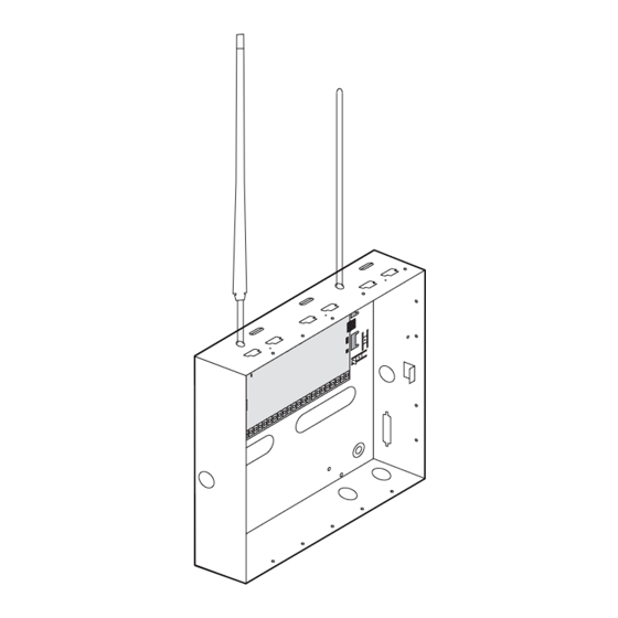
Concord 4 Installation Manual Antenna shrouds Install a plastic antenna shroud (included with panel) over each antenna and snap them into the holes on top of the enclosure (Figure 4). Skip this step for hybrid and commercial systems. Figure 4. Installing antenna shrouds Installing optional SnapCards Use the SnapCard header on the right side of the panel (Figure 5) to install an optional SnapCard. -
Page 29: Zone Inputs
Chapter 2 Installation The panel comes with factory programmed onboard hardwired zones. Install 2 kohm, end-of-line (EOL) resistors on all unused factory programmed onboard hardwired zones. If you don’t want to install EOL resistors, delete any unused zones from memory. Zone inputs Zone inputs 1 through 8 are supervised using included 2-ohm, end-of-line resistors at the last device on each circuit. - Page 30 Concord 4 Installation Manual Figure 7. Connecting 2- and 4-wire smoke detectors to the panel Panel terminals 2-wire smoke 4-wire smoke detectors detectors Note: The 2-wire smoke setting (in program mode) must be on when using four-wire smoke detectors as shown in Figure 7.
- Page 31 Chapter 2 Installation Figure 8. Polarity reversal module 2W SMK Output 2 +12V Zone 8 2K OHM First detector Last detector 49-454 EOL resistor Polarity reversal module 521NCSXT 521NCSXT Part # 406-03 Connecting 4-wire smoke detectors Terminal 24 provides power to 4-wire smoke detectors that latch and remain in the alarm state until power turns off, then restores to the detector.
-
Page 32: Connecting Speakers
Concord 4 Installation Manual Connecting speakers The panel provides one siren driver output for intrusion (steady), fire (temporal 3), and auxiliary (on-off-on- off) alarm sounds. This output trips only for partition 1 alarms. Install all sirens/speakers indoors in a concealed location. - Page 33 Chapter 2 Installation Figure 10. Connecting hardwired interior speakers Panel terminals Not used Not used...
-
Page 34: Connecting Exterior/Interior Piezo Sirens
Hardwired interior siren (13-949) This siren has two inputs; steady (#1) and warble (#2). Use the steady (#1) terminal for Concord 4 panels. The siren also includes a cover tamper switch that can be connected to a hardwired zone input on the panel, SnapCard or SuperBus 2000 hardwired input module. -
Page 35: Connecting An Interrogator 200 Audio Verification Module
Chapter 2 Installation Figure 12. Connecting an interior siren Panel terminals To zone input 2 kohm resistor Connecting an Interrogator 200 audio verification module Connect the Interrogator 200 audio verification module (AVM) to the panel terminals as shown in Figure 13. Partition 1 use only. -
Page 36: Connecting Superbus 2000 Touchpads
Concord 4 Installation Manual Connecting SuperBus 2000 touchpads SuperBus 2000 touchpads may have wires or screw terminals. All use the same wiring scheme for power and bus connections. Connect touchpads as shown in Figure 14. Figure 14. Connecting touchpads to the panel... - Page 37 Chapter 2 Installation Figure 15. Installing SuperBus 2000 modules Mounting Side Clips (6) Mounting Clip Screws Support Standoffs SuperBus 2000 2-amp power supply (600-1019) Refer to the power supply documentation for the mounting procedure. Note: Do not connect power (AC and battery) to the power supply until the panel is ready for power-up. For power supply AC and battery connections, see the SuperBus 2000 2 Amp Power Supply Installation Instructions.
-
Page 38: Superbus 2000 Voice-Only Module
Concord 4 Installation Manual Figure 17. Wiring transceivers and receivers to the panel Panel terminals Transceiver/receiver terminals SuperBus 2000 voice-only module The module can be mounted inside or outside of the control panel cabinet. Refer to the SuperBus 2000 Voice Only Module Installation Instructions included with each module, for complete mounting instructions.For... - Page 39 Chapter 2 Installation SuperBus 2000 phone interface/voice module The phone interface/voice module includes two backplates for mounting the module inside the control panel cabinet. You may also mount the module outside of the cabinet using an optional plastic housing (part no. 60- 800).
- Page 40 Concord 4 Installation Manual Wiring for status voice messages only Connect an interior speaker to the phone interface/voice module terminals as shown in Figure 20. When connected as shown, the speaker only produces status voice messages. In an alarm, the speaker announces voice status messages.
- Page 41 Chapter 2 Installation SuperBus 2000 energy saver module Connect the energy saver module to the panel and premises thermostat as shown in Figure 21. Figure 21. Wiring the thermostat and energy saver module to the panel Thermostat Energy saver module Panel terminals...
- Page 42 Concord 4 Installation Manual SuperBus 2000 8Z input and SuperBus 2000 4-relay output module Connect the modules to the panel as shown in Figure 22. Connect all necessary input and output wiring using the documentation that accompanies the module. Figure 22. Wiring input and output modules to the panel...
-
Page 43: Superbus 2000 Cellular Backup Module
Chapter 2 Installation SuperBus 2000 cellular backup module Connect the SuperBus 2000 cellular backup module to the SuperBus 2000 2-amp power supply and panel as shown in Figure 23. Figure 23. Wiring the cellular backup module to the panel SuperBus 2000 2-amp power supply terminals CAUTION: Since the SuperBus 2000 cellular backup module draws more than 1 amp, it must be powered by the... -
Page 44: Superbus 2000 Wireless Gateway-Ready Kit
Concord 4 Installation Manual SuperBus 2000 wireless gateway-ready kit Connect the SuperBus 2000 wireless gateway module to the SuperBus 2000 terminals as shown in Figure 25. Figure 25. Connecting a wireless gateway module to the panel SuperBus 2000 2-amp power supply terminals The panel cannot be used on a digital or PBX phone line. -
Page 45: Connecting The Phone Line To The Panel With A Db-8 Cord
Chapter 2 Installation 5. Check the phones on the premises for a dial tone and the ability to dial out and make phone calls. If phones do not work correctly, check all wiring and correct where necessary. See Troubleshooting page 126. Connecting the phone line to the panel with a DB-8 cord After installing the RJ31X jack, you are ready to connect the phone line to the panel. -
Page 46: Connecting The Ac Power Transformer
Concord 4 Installation Manual Connecting the AC power transformer The panel must be powered by a plug-in stepdown transformer that supplies 16.5 VAC, 40 VA (600-1023 or 600-1023-CN). CAUTION: Do not plug in the power transformer or connect the backup battery at this time. The panel must be... -
Page 47: Power
Chapter 2 Installation Power After connecting and wiring all devices to the panel, you are ready to apply AC and backup battery power to the panel. Note: The backup battery leads must be routed along the side of the enclosure and secured with a cable tie. To power up the panel see Figure 27 on page 36, and do the following: 1. - Page 48 Concord 4 Installation Manual...
-
Page 49: Programming
Chapter 3 Programming This chapter provides instructions on how to program the Concord 4 and includes descriptions of the programming settings. In this chapter: Overview ..........40 Tier 1 system programming menu. -
Page 50: Overview
Concord 4 Installation Manual Overview For onsite system programming, you must have an alphanumeric touchpad. Programming mode You must use an installer/dealer code (default = 4321) to enter program mode. You may place the system into programming mode only when you disarm all partitions. -
Page 51: Touchpad Programming Options
Chapter 3 Programming Touchpad programming options In program mode, touchpad buttons let you navigate to all installer programming menus for configuring the system. Table 8 describes the touchpad button functions in program mode. Table 8. Touchpad programming functions Button Programming function Select menu item or data entry. -
Page 52: Menu Navigation
Concord 4 Installation Manual Menu navigation There are two basic tiers of programming menus (Table 9). Table 9. Tier 1 and 2 menus System program- Phone ming Security Phones options Timers Light Touchpad Siren controls options Reporting options Audio Accessory... -
Page 53: Tier 1 System Programming Menu
Chapter 3 Programming Tier 1 system programming menu This section guides you through programming tier 1 System programming menu items as they appear in sequence. The exact order you follow depends on whether you’re installing a new system or changing programming in an existing system. -
Page 54: Partition 1 Copy
Concord 4 Installation Manual Partition 1 copy Default setting is None. After programming all settings pertaining to partition 1, you may make an exact copy to use for partitions 2 to 6. This helps reduce programming time when the system is set up for multiple partitions. If there are certain settings that are unique to partitions 2 to 6, simply advance to the appropriate menu and make the necessary changes. -
Page 55: Tier 2 Programming Menus
Chapter 3 Programming Tier 2 programming menus This section guides you through the following programming tier 2 menu items as they appear in sequence: • Security menu on page 46 • Phones menu on page 53 • Phone options menu on page 59 •... -
Page 56: Security Menu
Concord 4 Installation Manual Security menu The Security menu lets you choose whether security settings affect the whole system (Security - global settings) or a specific partition (Security partition 1 to 6 settings on page 50). To access global or partition security menu items, do the following: 1. - Page 57 Chapter 3 Programming Dealer code (0002) Default setting is None. The four-digit dealer code is used to prevent unauthorized persons from changing the programmed central station phone numbers and downloader code. When this feature is enabled, central station phone numbers and downloader code cannot be changed (unless you enter the program mode by using the dealer code).
- Page 58 Concord 4 Installation Manual Multipartition arm/disarm (0004) Default setting is Off. Partition to turn On. This feature controls which partitions can be armed/disarmed simultaneously when using a touchpad and access code assigned to those partitions. When enabled, users can arm/disarm selected partitions using an authorized access code.
- Page 59 Chapter 3 Programming Keyfob PTN (0006) Default setting is On. This feature controls which partitions the selected keyfob can arm/disarm. When enabled, the selected keyfob can arm/disarm the partitions selected in this menu. When disabled, the selected keyfob cannot arm/disarm multiple partitions.
-
Page 60: Security Partition 1 To 6 Settings
Concord 4 Installation Manual To disable keyfob PTN, do the following: 1. Enter this menu (display showing KEYCHAIN TP PTN), then press #. The display shows the lowest touchpad sensor number assignment such as: S1 P1 G0 TP RF where S1 is sensor 1, P1 is partition 1, G0 is sensor group 0, TP is touchpad and RF is wireless. - Page 61 Chapter 3 Programming Quick exit (0012 to 0062) Default setting is On. This feature determines whether or not users can open and close a standard entry/exit door without causing an alarm (while the system is armed). This feature also allows you to leave the armed premises without having to disarm and rearm the system.
- Page 62 Concord 4 Installation Manual To assign a keyswitch sensor, do the following: 1. With the display showing KEYSWITCH SENSOR nn (current sensor number), enter the desired sensor number (01–96). 2. The display flashes the entered sensor number. Press # and the display shows the new number.
-
Page 63: Phones Menu
Chapter 3 Programming Phones menu Use the Phones menu to set up central station reporting for the system. The Phones menu has the following types of submenus: • Central station phones 1 to 3 (see Phones central station 1 to 3 settings) •... - Page 64 Concord 4 Installation Manual High level reports (CS phone 1, 01001, CS phone 2, 01011, CS phone 3, 01021) Default setting for 1 is On and Off for 2 and 3. When this setting is on, the following conditions report to the central station: •...
- Page 65 Chapter 3 Programming Open/close reports (01004, 01014, and 01024) Default setting is Off. This setting determines whether opening and closing reports are sent to the central station. When turned on, the panel sends a closing report when the system is armed and an opening report when the system is disarmed. Note: To use this feature, the opening reports and closing reports settings under the Reporting menu...
-
Page 66: Phones - Pager Phone 1 To 5 Settings
Concord 4 Installation Manual Phones - pager phone 1 to 5 settings The following describes how to program the Phones settings that appear under Pager phone 1 to 5. Cellular backup (01030, 01040, 01050, 01060, and 01070) Default setting is None. - Page 67 Chapter 3 Programming Low level reports (01032, 01042, 01052, 01062, and 01072) Default setting is Off. This setting determines whether the following nonalarm conditions report to a pager: • Force armed • Hardwired zone trouble (open or short) • Supervisory (wireless devices) •...
-
Page 68: Phones - Downloader Phone Settings
Concord 4 Installation Manual Streamlining (01036, 01046, 01056, 01066, and 01076) Default setting is On. This setting determines whether the panel includes (off) or excludes (on) the account number when reporting to a pager. To turn streamlining off or on, do the following: 1. -
Page 69: Phone Options Menu
Chapter 3 Programming Phone options menu The Phone options menu lets you set up system phone access and communication that affect the whole system (see Phone options - global settings) or a specific partition. Phone options - global settings The following describe how to program the Phone options settings that appear under Global. Phone test (02000) Default setting is On. - Page 70 Concord 4 Installation Manual To turn automatic test reset off or on, do the following: 1. With the display showing AUTO TEST RESET OFF/ON (current setting), press 1 (off) or 2 (on). 2. The display flashes the entered setting. Press # and the display shows the new setting.
- Page 71 Chapter 3 Programming Cancel message (02007) Default setting is On. This setting determines whether or not the panel displays a cancel message after the user disarms the system to clear an alarm condition. To turn cancel message on or off, do the following: 1.
-
Page 72: Phone Options - Partition 1 To 6 Settings
Concord 4 Installation Manual Dial tone detect (02010) Default setting is On. When this setting is on, the panel begins dialing as soon as it detects a dial tone. When this feature is off, the panel begins dialing a few seconds after seizing the phone line. - Page 73 Chapter 3 Programming 2. Hang up. 3. Call the premises again within the next 10 to 40 seconds. The system answers after the first ring. When this feature is off, the system answers after 12 full rings. To turn this feature off or on, do the following: 1.
- Page 74 Concord 4 Installation Manual Phone panic (0216 to 0266) Default setting is Off. This setting determines whether or not a police panic alarm can be activated from a touch tone phone. When this feature is on, pressing # + ****** from a touch tone phone on the premises causes a panic alarm.
-
Page 75: Timers Menu
Chapter 3 Programming Timers menu Use the Timers menu to set up the various system feature times that affect the whole system (see Timers -global settings) or a specific partition (Timers - partition 1 to 6 settings on page 67). Timers -global settings The following describes how to program the Timers menu settings that appear under Global. - Page 76 Concord 4 Installation Manual Phone test freq. (0303) Default setting is 7 days. This setting determines how often the panel conducts the automatic phone test (see HONE OPTIONS GLOBAL on page 59). The system can be set to perform an automatic phone test anywhere from every day to SETTINGS every 255 days.
-
Page 77: Timers - Partition 1 To 6 Settings
Chapter 3 Programming Activity timeout (0306) Default setting is 24 hours. This setting determines when the system sends a no activity report. The panel can be set to wait from 1 to 42 hours. If no user interaction or device activation occurs in that time, the panel sends a report to the central station. - Page 78 Concord 4 Installation Manual To set the Exit delay, do the following: 1. With the display showing EXIT DELAY nnn SECS (current setting), enter the time value (45 to 184 seconds). 2. The display flashes the entered setting. Press # and the display shows the new setting.
- Page 79 Chapter 3 Programming No usage time (0315 to 0365) Default setting is None. This setting determines how many days a partition can remain disarmed before the panel sends a no usage report to the central monitoring station and stores the event in the history buffer. When this feature is set: •...
-
Page 80: Light Control Menu
Concord 4 Installation Manual Light control menu The Light control menu lets you set up light activation for a specific partition. Note: For light control to work, you must power the panel with a power line carrier transformer and X10 powerhouse lamp modules must be installed at desired lamps. -
Page 81: Touchpad Options Menu
Chapter 3 Programming Touchpad options menu The Touchpad options menu lets you set up touchpad panic and arming operations that affect the whole system (see Touchpad options - global settings) or a specific partition (Touchpad options - partition 1 to 6 settings). - Page 82 Concord 4 Installation Manual Police panic (0512 to 0562) Default setting is On. This setting determines whether touchpad police panic buttons are enabled (on) or disabled (off). To change the setting, do the following: 1. With the display showing POLICE PANIC OFF/ON (current setting), press 1 (off) or 2 (on).
-
Page 83: Reporting Menu
Chapter 3 Programming Reporting menu The Reporting menu lets you set up which system events are reported to the central monitoring station that affect the whole system (see Reporting - global settings) or a specific partition (Reporting - partition 1 to 6 settings on page 78). - Page 84 Concord 4 Installation Manual Buffer control (06002) Default setting is Off. When this setting is on, only arming level changes and time changes (system time and daylight saving time) are logged in the buffer (memory) of the panel. When this setting is off, all system events are logged in the buffer.
- Page 85 When this setting is on, the panel reports a restoral to the central monitoring station for wireless or hardwire zones in alarm before the alarm is canceled. Note: As with all GE Security panels, hardwired smoke detectors connected to panel or SnapCard hardwired zones do not send restorals. To turn the setting off or on, do the following: 1.
- Page 86 Concord 4 Installation Manual TP panic TRPT FMT (06010) Default setting is Off. This setting determines how the panel formats touchpad panic alarm reports to the central station. When this feature is turned on, touchpad panic alarms report using the following 3-digit codes: •...
- Page 87 Chapter 3 Programming RF low battery report (06013) Default setting is Weekly. This setting determines whether the panel sends daily or weekly low battery reports to the central monitoring station when a wireless device is reporting a low battery condition to the panel. To set RF low battery report to daily or weekly, do the following: 1.
-
Page 88: Reporting - Partition 1 To 6 Settings
Concord 4 Installation Manual Aux power fail (06016) Default setting is On. When this setting is on, the panel sends a report to the central monitoring station if the 12 VDC power outputs on the panel and/or SuperBus 2000 2-amp power supply fail. - Page 89 Chapter 3 Programming Note: To use this feature, the Open/close reports settings under the Phones menu on page 53 must be turned on for the specific CS phone or pager number. To turn the setting off or on, do the following: 1.
- Page 90 ) + CODE + 6 (Latchkey) within an assigned time schedule sends a page. Refer to the Concord 4 User Manual for complete latchkey setup and operation. To turn the setting off or on, do the following: 1. With the desired partition selected, press A or B until the display shows LATCHKEY FORMAT OFF/ ON (current setting).
- Page 91 Chapter 3 Programming Freeze temp (06107 to 06607) Default setting is 42°F. This setting determines the temperature point the EnergySaver module detects a potential freeze (heating failure) condition. The adjustable range is from 40 to 90°F. Note: This is the same menu found under Accessory modules - bus devices settings on page 93.
- Page 92 Concord 4 Installation Manual Report confirm (06111 to 06611) Default setting is Off. When this setting is on, system status speakers announce “Report is okay” followed by a single beep each time a successful report is made to the central monitoring station. When turned off, no status message or beep sounds.
-
Page 93: Siren Options Menu
Chapter 3 Programming Siren options menu The Siren Options menu lets you set up siren operation and supervision that affect the whole system (see Siren options - global settings) or a specific partition (Siren options - Partition 1 setting on page 84). Siren options - global settings The following describes how to program the Siren options menu settings that appear under Global. -
Page 94: Siren Options - Partition 1 Setting
Concord 4 Installation Manual Global fire (0703) Default setting is Off. This setting determines whether or not sirens in all partitions sound (on) if any partition activates a fire alarm. To turn the setting off or on, do the following: 1. -
Page 95: Sensors Menu
Chapter 3 Programming Sensors menu The Sensors menu gives you access to the following settings: Learn sensors. Add (learn) hardwired zones, wireless sensors, and wireless touchpads into panel memory. Sensor text. Name the sensors and zones you have added to the system. Delete sensors. - Page 96 Concord 4 Installation Manual Learn sensors (080) Default setting is None. The panel comes with factory programmed onboard hardwired zones. Install 2 kohm, end of line (EOL) resistors on all unused factory sensors programmed on to Table 10, Tripping sensors and hardwired zones.
- Page 97 Chapter 3 Programming Sensor text (081) Default setting is None. Use the following guidelines to name zone and sensor locations: • Use the item numbers that appear in Table 26 on page 164 for characters and words listed there. • If a desired word does not appear in Table 26 on page 164 create it using the characters (custom text).
- Page 98 Concord 4 Installation Manual Edit sensors (083) Default setting is None. This menu lets you view and, if desired, change the group and partition assignment for each learned zone or sensor. For example, the display shows: CODE 1> S01 P1 G13 NC HW BACK DOOR Where S01 is the zone/sensor number, P1 is partition 1, G13 is sensor group 13, NC is normally closed, HW is hardwired, and BACK DOOR is the programmed text name.
-
Page 99: Audio Verification Menu
Chapter 3 Programming Audio verification menu The Audio verification menu lets you set up the audio verification module (AVM) operation in partition 1. If you want audio verification for partitions 2 to 6, you must install a standalone audio verification module and a 4-relay output module (HOM) (60-770) output for that partition. - Page 100 Concord 4 Installation Manual Fire shutdown (09002) Default setting is Off. This setting determines whether system sirens turn off during a fire alarm audio session. To turn the setting off or on, do the following: 1. With the display showing AUDIO VERIFY OFF/ON, press A or B until the display shows FIRE SHUTDOWN OFF/ON (current setting).
- Page 101 Chapter 3 Programming Access code (09006) Default setting is **** or None. This setting determines the code required to access the audio verification module to start an audio session. If no code is programmed, pressing * starts an audio session. To change the Access code, do the following: 1.
- Page 102 Concord 4 Installation Manual Manual mic gain (09009) Not used. Vox RX gain (09010) Default setting is 08. This setting determines the receiver (talkback) gain level for voice-activated switching (VOX). Setting range is 01 to 10. If the VOX is switching the speaker on when the central station operator is not talking, lower this setting and the VOX mic gain setting.
-
Page 103: Accessory Modules Menu
Chapter 3 Programming Accessory modules menu The Accessory modules menu gives you access to the following menus: Bus devices. This menu lets you read bus device unit numbers, assign bus devices to a partition, and configure other features associated with a specific bus device. SnapCards. -
Page 104: Output Programming
Concord 4 Installation Manual 4. Remove AC and battery power from the panel. 5. Replace the defective bus device with a new one. 6. Apply AC and battery power to the panel. Partition assign This menu lets you assign bus devices to work in the desired partition. - Page 105 Chapter 3 Programming Status beeps Default setting is On. This setting determines whether or not the selected touchpad sounds status beeps. Each touchpad can be set individually. This feature is usually turned off for a touchpad that is located in or near bedrooms, to avoid disturbing sleeping persons.
-
Page 106: Accessory Modules - Snapcard Settings
Concord 4 Installation Manual Temperatures Default setting is None. This setting lets you adjust the energy saver module (ESM) room temperature setting to match the premises thermostat. The adjustable range is from 40 to 90°F. Note: To ensure accuracy, wait at least 15 minutes before setting the ESM temperature to allow the ESM to warm or cool to actual room temperature. - Page 107 Chapter 3 Programming 2. Press # again and the display shows OUTPUT 1. 3. Press A or B to select the desired output (1 to 4), then press #. 4. With the display showing PARTITION ASSIGN 1, press 1 to 6 to select the desired partition. Press # to confirm the partition.
- Page 108 Concord 4 Installation Manual Output text (10120 to 10123) Default setting is None. Entering text for an output allows the user to control it directly or by schedule. Use the following guidelines to name SnapCard outputs: • Use the item numbers that appear in Appendix C,...
-
Page 109: Onboard Options Menu
Chapter 3 Programming Onboard options menu The Onboard options menu lets you set up the following built-in options: Inputs. This menu lets you turn the smoke verification and the two-wire smoke features off or on. (See Onboard options - inputs settings.) Output programming. -
Page 110: Onboard Options - Output Programming Settings
Concord 4 Installation Manual Onboard options - output programming settings The following section describe the Onboard options menu settings that appear under Output programming. Output 1, 2 Shortcuts are: Output 1 partition assignment (11100), configuration (11101); Output 2 partition assignment (11110), configuration (11111). -
Page 111: Onboard Options - Output Text Settings
Chapter 3 Programming Onboard options - output text settings The following section describe the Onboard options menu settings that appear under Output text. Output text (1120 to 1121) Default setting is None. Entering text for an output allows you to control it directly or by schedule. Use the following guidelines to name onboard outputs: •... -
Page 112: Macro Keys Menu
Concord 4 Installation Manual Macro keys menu The Macro keys menu lets you set up single-button system commands with the ATP2100 and ATP2600 touchpads. Macro keys - partition 1 to 6 settings The following describes how to program the Macro keys menu settings that appear under Partition 1 to 6. -
Page 113: Quick Programming Mode
Chapter 3 Programming Quick programming mode Use the quick programming mode to program basic system programming with a SuperBus 2000 fixed display touchpad, SuperBus 2000 FTP 1000 touchpad, or any SuperBus 2000 alphanumeric touchpad. The following menus are accessible: • Account number (all partitions) •... -
Page 114: User Programming Mode
Concord 4 Installation Manual User programming mode Use user programming mode to view system version information and program the following system settings: • Time and date menu on page 104. • User codes menu on page 105. • Options menu on page 108. -
Page 115: User Codes Menu
Chapter 3 Programming User codes menu The User codes menu lets you program/change regular user access codes, partition master codes, and the system master code. You can enter up to 230 separate user codes, allowing up to 230 different users access to the security system. - Page 116 Concord 4 Installation Manual Remote access (030nnn2 where nnn is user number 000 to 229) Default setting is Off. This setting determines whether the user can access the panel from a remote phone (a phone located off the premises). To turn the setting off or on, do the following: 1.
- Page 117 Chapter 3 Programming Partition assign (030nnn5 where nnn = user number 000 to 229) Default setting is Ptn 1. This setting determines which partitions a user code can access. A code can be assigned to all partitions if desired, making it usable at any touchpad in any partition and able to jump to any selected partition. To assign partitions to a user code, do the following: 1.
-
Page 118: Options Menu
Concord 4 Installation Manual Options menu The Options menu lets you set up the system for downloading and silent arming. You can also adjust alphanumeric touchpad display brightness from this menu Downloading (041) Default setting is On. When this setting is on, the panel can communicate with Enterprise Downloader software for programming the system from offsite. -
Page 119: Set Up Schedules Menu
Chapter 3 Programming Voice chime (045) Default setting is On. This setting determines whether speakers connected to the phone interface/voice module or voice-only module announce perimeter sensor/zone numbers that are tripped when the chime feature is on. This menu appears only if a phone interface/voice module or a VOM is connected to the panel. -
Page 120: Attached Schedules To Events Menu
Installation Manual Note: If you are programming schedules for your customer, be sure to record the settings in the Concord 4 User Manual. To set up a time schedule, do the following: 1. Press A or B until the display shows SET UP SCHEDULES. - Page 121 Chapter 3 Programming 4. Press 1 (off) or 2 (on). The display flashes the entered selection. Press # and the display shows the new setting for the selected schedule. Exception reports (opening: 062nn, closing: 063nn, where nn is schedule number) This setting lets you attach the exception opening report feature and the exception closing report feature to time schedules.
-
Page 122: Energy Saver Menu
Concord 4 Installation Manual Outputs (065xnn where nn is schedule number and x is output number minus 1) Default setting is Off. This setting lets you attach outputs to a time schedule. Onboard outputs are 1 to 2, SnapCard outputs are 3 to 6. -
Page 123: Attach Lights To Sensors Menu
Chapter 3 Programming Note: The low setpoint cannot be set equal to or higher than the high setpoint. To set the low setpoint, do the following: 1. With the display showing Energy Saver, press #, then A or B until the display shows LOW SETPOINT NN DEGREES (current setting). -
Page 124: System Version Menu
Concord 4 Installation Manual System version menu The System version menu lets you view and identify panel hardware and software. This information is primarily used for troubleshooting purposes. System version (factory code: 010, system number: 011, system level: 012, software version: 013) This menu lets you view and identify panel hardware and software version. -
Page 125: Downloader Programming
Chapter 3 Programming Downloader programming The panel can be programmed remotely using Enterprise Downloader. Use the information you recorded in Appendix A, System planning sheets to inform the downloading operator of the programming requirements for this system. A Downloader phone number should be programmed and the user-programmable option Downloading must be powered on for remote downloader programming to work. -
Page 126: Testing The System
Cellular backup communication on page 124 Basic system commands Table 13 describes basic touchpad operating commands. For complete details on system operation, including user programming, refer to the Concord 4 User Manual.. Table 13. Basic touchpad commands Command System response... - Page 127 Chapter 3 Programming Table 13. Basic touchpad commands Command System response 7 + 4 Partition jump without entering code (only if partition security option is off) 7 + 6 Identifies alarms in memory 7 + 7 + n (n = output number [1–6]) Turns the output on or off.
-
Page 128: Zones/Sensors
Concord 4 Installation Manual Zones/sensors Test sensors/zones after all programming is completed; whenever there is a change in environment, equipment, or programming; and whenever a zone- or sensor-related problem occurs. If the system does not respond as described in the following procedure, see Troubleshooting on page 126. -
Page 129: Phone Communication
Chapter 3 Programming Phone communication Do a phone test to check the phone communication between the panel and the central monitoring station. To test phone communication, do the following: 1. Contact the central monitoring station to inform them that you are testing the system. 2. - Page 130 Concord 4 Installation Manual Table 14 describes pager system event codes. Table 14. Pager system event codes Codes System event Zone restoral System disarmed Sensor test exit Trouble condition cleared Alarm canceled System armed to STAY System armed to AWAY...
-
Page 131: Outputs And Sirens
Chapter 3 Programming Outputs and sirens You should test all outputs (onboard and SnapCard) to verify configuration programming. Note: Be sure to contact the central monitoring station before activating outputs that trigger from an alarm condition. To test outputs, do the following 1. -
Page 132: Energy Saver Module (Esm)
Concord 4 Installation Manual Energy saver module (ESM) Test the energy saver module to verify it overrides the thermostat. Note: The system must have high- and low-temperature limits set to test the energy saver module. To test the energy saver module, do the following: 1. -
Page 133: Audio Verification Module Communication
Chapter 3 Programming Audio verification module communication Test the audio verification module (AVM) from offsite and the central station to verify that it works properly. You will need a helper and DTMF phone at an offsite location to perform this test. When testing the AVM from offsite you must follow these guidelines: •... -
Page 134: Cellular Backup Communication
Concord 4 Installation Manual Cellular backup communication To check the cellular communication between the panel and the central monitoring station, do the following: 1. Contact the central monitoring station to inform them that you are testing the system. 2. Install and activate the SuperBus 2000 cellular backup module. -
Page 135: Chapter 4. Troubleshooting, Maintenance, Support
......... . .126 Troubleshooting your Concord 4 system. -
Page 136: Troubleshooting
Panel power issues • What transformer does Concord 4 use? Concord 4 uses a 16.5 VAC transformer, (600-1023 or 600-1024 with power line carrier). Concord 3 uses a 24 VAC transformer. Using a 24 VAC transformer on Concord 4 damages the panel. - Page 137 Chapter 4 Troubleshooting, maintenance, support • The touchpads flash AC or display AC Power Failure/AC Failure After pressing STATUS the panel continues to operate from backup battery. This could be caused by a number of things. Do the following: 1. Check the AC circuit breaker to be sure the circuit is live. 2.
- Page 138 Concord 4 Installation Manual Bypassing issues • Touchpad indicates Invalid and/or “Invalid” is heard when you attempt to bypass a sensor. 1. You may be attempting to bypass a 24-hour sensor that cannot be bypassed (group 26 fire sensors). 2. The sensor is not active in the current arming level.
- Page 139 Chapter 4 Troubleshooting, maintenance, support 4. Check for correct phone line wiring between the TELCO block and the RJ31X/CA-38A jack. Alphanumeric touchpad issues • Display shows all ************. Touchpad is not connected to panel bus terminals or is wired incorrectly. Check and correct wiring. •...
- Page 140 Concord 4 Installation Manual Check for correct output partition assignment. Check that your wires are connected to the appropriate terminals: 1. Output 1 (exterior) uses terminals 9 (positive) and 13 (ground). 2. Output 2 (interior, follows status beeps) uses terminals 11 (positive) and 10 (ground).
- Page 141 Chapter 4 Troubleshooting, maintenance, support Change mounting position of sensor (from horizontal to vertical or vice versa) and test sensor several times for consistency. Sensor signal is not reaching panel/receiver because sensor is too far away. Remove sensor from mounted location and test from other locations.
- Page 142 Concord 4 Installation Manual Check that the HOUSE dial on the X10 module matches the partition house code programmed into the panel. Panel is not powered by a power line carrier transformer. Replace existing transformer with a power line carrier transformer.
-
Page 143: Contacting Technical Support
Chapter 4 Troubleshooting, maintenance, support Contacting technical support For assistance installing, operating, maintaining, and troubleshooting this product, refer to this document and any other documentation provided. If you still have questions, you may contact technical support during normal business hours (Monday through Friday, excluding holidays, between 5 a.m. and 5 p.m. Pacific Time). Table 18. - Page 144 Concord 4 Installation Manual...
-
Page 145: Appendix A System Planning Sheets
Appendix A System planning sheets This appendix provides a list of the various system planning sheets for the Concord 4. In this appendix: System planning sheets ........140 Wireless devices . -
Page 146: System Planning Worksheets
Concord 4 Installation Manual System planning worksheets Table 19. Customer information Customer name Address City County State Phone Table 20. Wireless devices Part no. Description Qty. 60-362 Door/window sensor 60-670-95R SAW door/window sensor 60-741-95 Micro recessed door/window sensor 60-499 Slim line door/window sensor... - Page 147 Part no. Description Qty. 60-639-95R SAW indoor PIR motion sensor 60-639-95R-OD SAW outdoor PIR motion sensor (not for intrusion protection) 60-703-95 Crystal indoor PIR motion sensor 60-834-95R Adjustable dual technology sound sensor 60-597 HiTech handheld wireless touchpad 60-607* 2-button keyfob touchpad 60-606* 4-button keyfob touchpad 60-659-95R*...
- Page 148 Concord 4 Installation Manual Table 21. Hardware devices Part no. Description Qty. mA (max.) Subtotal 60-836 Voice only module (with current jumper installed) (with 600mA current jumper removed) 60-777-01 Phone interface/voice module 600 mA 600-1025-01-95R RF transceiver 55 mA 60-764-01-95R...
- Page 149 Table 22. Zone and sensor assignments Module bus ID Module input RF zone number number Group Partition Zone/sensor text...
- Page 150 Concord 4 Installation Manual Table 22. Zone and sensor assignments Module bus ID Module input RF zone number number Group Partition Zone/sensor text...
- Page 151 Table 22. Zone and sensor assignments Module bus ID Module input RF zone number number Group Partition Zone/sensor text...
- Page 152 Concord 4 Installation Manual Table 22. Zone and sensor assignments Module bus ID Module input RF zone number number Group Partition Zone/sensor text Table 23. System settings index and record Setting (reference) default Shortcut no. Setting Installer programming—8 + installer/dealer CODE + 00...
- Page 153 Table 23. System settings index and record Setting (reference) default Shortcut no. Setting Beep delay 2 sec 09005 Buffer control off 06002 Buffer full report off 06007 Bypass reports off 06004 Call wait cancel none 02009 Cancel message on 02007 Cellular backup CS phone 1 on, CS phone 2-3 off 01007, 01017, 1_____________2_____________...
- Page 154 Concord 4 Installation Manual Table 23. System settings index and record Setting (reference) default Shortcut no. Setting Exit extension on 0013-0063 Extended delay 4 min 0312-0362 Fire panic on 0510-0560 Fire shutdown off 09002 Force armed off 06104-06604 Freeze alarm off...
- Page 155 Table 23. System settings index and record Setting (reference) default Shortcut no. Setting Manual mic gain 09009 Multiple-partition arm off 0005 Next phone test 7 days 0304 No activity off 06102 - 06602 Open/close reports (phones) off 01004, 01014, 1_____________2_____________ 3___________ 01024 Open/close reports (pagers) off...
- Page 156 Concord 4 Installation Manual Table 23. System settings index and record Setting (reference) default Shortcut no. Setting RF TX timeout 12 hrs 0302 Ring/hang/ring on 0212-0262 Reporting format (SIA/CID) 01006, 01016, 1_____________2_____________ 3___________ 01026 Sensor text none Silent talkback off...
-
Page 157: Appendix B Settings
Appendix B Settings This appendix provides a list of alarm panel settings. -
Page 158: Settings
Concord 4 Installation Manual Settings Table 24 shows a higher view of menuu navigation. Table 25 shows detailed menu navigation. To navigate through your system menus, use A and B to scroll through across main menus, and at times up and down through submenus. - Page 159 Exception rpts on off (01013) Latchkey rpts on off (01055) Open/close reports on off (01014) Streamlining on off (01056) Timers Ptn assignment 123456 (01057) Pager 4 Global (continued) Phone number none (01060) Next phone test 7 days (1-255) (0304) High lvl rpts on off (01061) Output trip time 4 sec (1-12) (0305) Low lvl rpts on off (01062) Activity timeout 24 hours (1-42) (0306)
- Page 160 Concord 4 Installation Manual Timers Freeze alarm on off (06106 - 06606) Global Freeze temp 42 (40-90) (06107 - 06607 Supervisory time 1:00 - 4:00 (random) (0300) Alarm verify on off (06108 - 06608) Accessory modules System tamper on off (06109 - 06609)
- Page 161 Audio verifyon off(09000) Configuration Audio mode 1(09001) Configuration Fire shutdown on off (09002) Output text Silent talkback on off (09003) Output 1 (10120) Access timeout 90 sec (30-300) Output 2 (10121) Beep delay 2 sec (0-300) (09005) Output 3 (10122) Access code * * * * (09006) Output 4 (10123) VOX mic gain 14 (01-64) (09007)
- Page 162 Concord 4 Installation Manual Table 25. Tier two menus System programming Security Phones Clear memory Installer code Quick arm High lvl rpts High lvl High lvl rpts rpts 4321 on off on off on off on off (0001) (0011 - 0061)
- Page 163 Phones (cont.) Pager 1 Pager 2 Pager 3 Pager 4 Pager 5 Downlo ader phone Phone number Phone Phone Phone Phone Phone number number number number number none none none none none none (01030) (01040) (01050) (01060) (01070) 01090 High lvl rpts High lvl rpts High lvl rpts High lvl rpts...
- Page 164 Concord 4 Installation Manual Phones (cont.) Ptn assignment assignment assignment assignment assignment 1 2 3 4 5 6 1 2 3 4 5 6 1 2 3 4 5 6 1 2 3 4 5 6 1 2 3 4 5 6...
- Page 165 Phone options Timers Light control DTMF dialing Toll saver Output trip time Sleep time on off on off 4 sec (1-12) 22:00 (00:00- 23:50) (02004) (0214 - 0264) (0305) (0314 - 0364) Dial abort delay Phone panic Activity timeout No usage time 30 sec (15-45) on off 24 hours (1-42)
- Page 166 Concord 4 Installation Manual Touchpad options Reporting Latchkey zones Fire panic 24-hour tamper Opening reports none (1-96) on off on off on off (0500) (0510 - 0560) (06000) (06100 - 06600) Auxiliary panic Antenna tamper Closing reports on off on off...
- Page 167 Touchpad options Reporting Zone restorals Alarm verify on off on off (06008) (06108 - 06608) Two trip error System tamper on off on off (06009) (06109 - 06609) TP panic rpt fmt Report confirm on off on off (06010) (06111 - 06611) AC failure on off (06011)
- Page 168 Concord 4 Installation Manual Siren options Sensors Global Partition Learn Sensor text Delete sensors Edit sensors Sensors Immediate Siren verify Sensor Text for Delete sensor Sn P1 Gnn beeps partition sensor on off NC/NO/TP on off 1 2 3 4 5 6 (0710—Ptn...
-
Page 169: Appendix C. Reference Tables
Audio Accessory verification modules Partition 1 Bus device SnapCards (see next page) Audio verify Unit - ID on off on off (09000) (10000 - 10015) Audio mode Change ID Device ID nnnnn (09001) Fire shutdown Device partitions Partition assign on off 1 2 3 4 5 6 (09002) Silent talkback... - Page 170 Concord 4 Installation Manual Audio Accessory verification modules VOX mic gain 14 (01-64) (09007) VOX gain range 64 (01-64) (09008) Manual mic gain 04 (cannot change) (09009) VOX RX gain 08 (01-10) (09010) Accessory modules (cont.) Snapcard Output Output text...
- Page 171 Accessory modules (cont.) Output 3 Partition assign Configuration Output 3 Output 3 1 2 3 4 5 6 00903 (10122) item n (101120) (101121) Output 4 Partition assign Configuration Output 4 Output 4 1 2 3 4 5 6 01003 (10123) Item n (101130)
- Page 172 Concord 4 Installation Manual...
-
Page 173: Reference Tables
Appendix C Reference tables This appendix provides a list of reference tables. In this appendix: Sensor group characteristics ....... . 164 Cross zoning . -
Page 174: Reference Tables
Installation Manual Reference tables This table shows what the sensors on your Concord 4 system do. Every sensor is assigned to a group, and this table specifies those groups and functions. Every device must be assigned to one of these groups. - Page 175 Table 25. Sensor group characteristics (continued) Supervi Chime Active Name Application Alarm Delay Restoral sory Report (Level) levels Instant Interior doors (Hardwired) Police Follower interior Instant Interior PIR motion Police Follower interior sensors. * (RF wireless) Instant Interior doors. (Hardwired) Police Follower interior...
- Page 176 Concord 4 Installation Manual Table 25. Sensor group characteristics (continued) Supervi Chime Active Name Application Alarm Delay Restoral sory Report (Level) levels Auxiliary Freeze sensor. Auxiliary Instant 1,2,3 Output HOM, PIR motion sensor, Silent Instant 1,2,3 module sound sensor or pressure mat.‡...
- Page 177 Cross zoning Cross-zoning (two-trip) refers to two different group 18 sensors that must be tripped within two minutes of each other to report an alarm to the central station. Figure 29 shows the path of a person walking from the kitchen to the living room.
- Page 178 Concord 4 Installation Manual Table 26. Item numbers and sensor text Item Item Sensor Sensor Item Sensor Item # Sensor text Sensor text text Item # text Item # Sensor text text Aborted Date North North Daughters Glass Access Degrees...
- Page 179 Table 26. Item numbers and sensor text Item Item Sensor Sensor Item Sensor Item # Sensor text Sensor text text Item # text Item # Sensor text text Bypassed Father’s Load Report Cabinet Feature Loading Canceled Fence Right Fire Lower Room Carbon First...
- Page 180 Concord 4 Installation Manual Table 27. System event trigger numbers System event Description Trigger no. AVM is interactive (audio session in When the central station operator begins listening or progress) talking to the premises. Fail-to-communicate (panel can’t call CS or When the fail-to-communicate output is activated.
- Page 181 Table 28. Sensor group event trigger numbers Sensor group Trigger no. Sensor group Trigger no. Group 09 in alarm Group 26 in alarm Group 10 in alarm Group 27 in alarm Group 11 in alarm Group 28 in alarm Group 12 in alarm Group 29 in alarm Group 13 in alarm Group 30 in alarm...
- Page 182 Concord 4 Installation Manual Table 29. Sensor number event trigger numbers Sensor Number State Trigger no. State Trigger no. Sensor 20 in alarm open Sensor 21 in alarm open Sensor 22 in alarm open Sensor 23 in alarm open Sensor 24...
- Page 183 Table 29. Sensor number event trigger numbers Sensor Number State Trigger no. State Trigger no. Sensor 51 in alarm open Sensor 52 in alarm open Sensor 53 in alarm open Sensor 54 in alarm open Sensor 55 in alarm open Sensor 56 in alarm open...
- Page 184 Concord 4 Installation Manual Table 29. Sensor number event trigger numbers Sensor Number State Trigger no. State Trigger no. Sensor 82 in alarm open Sensor 83 in alarm open Sensor 84 in alarm open Sensor 85 in alarm open Sensor 86...
-
Page 185: Appendix D. Hardware
Table 30. System feature event trigger numbers Feature State Trigger no. Phone test initiated AC failure for 15 minutes CPU low battery detected (excluding first minute after power-up) Auto phone test begun Receiver failure detected Back in service alarm (AC loss, battery drain, then AC restore) Phone failure detected Buffer full... - Page 186 Concord 4 Installation Manual Table 31. Response characteristics Response characteristics Description Momentary trip time The point remains active for nn seconds (n is 1-12 seconds). The default is 4 seconds. 3 minute trip time The point remains active for three minutes.
- Page 187 Table 32. Response numbers Siren tracking Trip delay Response time Response no. momentary 3 minutes siren time sustained momentary 3 minutes siren time sustained momentary 3 minutes siren time sustained momentary 3 minutes siren time sustained Notes for response numbers The mechanical lifetime of the relay may be exceeded if an output is set up for a siren tracking response and a pulsing siren (auxiliary or fire) is active for long time periods.
- Page 188 Concord 4 Installation Manual...
-
Page 189: Specifications
Appendix C Hardware This appendix provides specification requirements as well as system wiring notes. In this appendix: Specifications ..........System wiring notes . -
Page 190: Specifications
Concord 4 Installation Manual Specifications Power Requirements: Class 2, 16.5 VAC, 40 VA, 60 Hz (part no. 600-1023 or 600-1024) Rechargeable Batteries:12 VDC, 4.5 or 5.0Ah Lead-Acid (part no. 60-681) OR 12 VDC, 7Ah (part no. 60- 680). The battery will last 24 hours with no AC and specified standby load Radio Frequency: 319.5 MHz... - Page 191 Figure 29. System diagram...
- Page 192 Concord 4 Installation Manual Figure 30. Other SuperBus 2000 module connections...
-
Page 193: System Wiring Notes
System wiring notes Table 33 explains the various component functionality as shown in Figure 29 on page 165 and Figure 30 on page 166. Table 26. System wiring notes Class 2 power transformer must be plugged into an Some telephones are polarity-sensitive. Green and red unswitched AC power receptacle. - Page 194 Concord 4 Installation Manual...
-
Page 195: Index
Index AC power transformer................36 Light control..................121 access code ................... 127 antenna shrouds ..................18 Arming and disarming................127 macro keys menu.................. 102 Audio verification................... 89 menu ....................... 53 Audio verification module..............123 Menu navigation..................42 Mounting ....................16 Bypassing ..................... - Page 196 Concord 4 Installation Manual Reporting menu ..................73 technical support .................. 133 Response Numbers ................173 Touchpad display contrast..............122 RJ 31X phone jack ................. 34 Touchpad options menu ................. 71 Touchpad programming options ............41 troubleshooting..................126 safety terms and symbols ...............vii Security menu global settings ..................
Need help?
Do you have a question about the Concord 4 and is the answer not in the manual?
Questions and answers