
Subscribe to Our Youtube Channel
Related Manuals for GE Security CS575


Summary of Contents for GE Security CS575
-
Page 1: Alarm System
Security CS875-575-375-275-175 Alarm system Installers Manual with CS5500 keypad imagination at work 1052xxx... - Page 2 1999/5/EC (R&TTE) based on test results using (non)harmonized standards in accordance with the Directives mentioned. www.gesecurity.com Copyright (c) 2005 GE Security B.V.. All rights reserved. GE Security B.V. grants the right to reprint this manual for internal use only. GE Security B.V. reserves the right to change information without notice.
-
Page 3: Table Of Contents
4.1.2 Dual wiring ........................A-4-1 4.1.3 Single wiring .......................A-4-1 4.2 Installing the control unit ....................A-4-1 4.2.1 CS575M/CS875M (large metal housing) ..............A-4-2 4.2.2 CS275/CS375/CS575/CS875 (polycarbonate housing) ..........A-4-4 4.2.3 CS175M/CS275M/CS375M/CS575SM (small metal housing) ........A-4-6 4.3 Installing the keypad ....................A-4-8 4.3.1 Wiring the keypad .......................A-4-8 4.3.2 Wiring several keypads together ................A-4-9... - Page 4 5.7 Editing text ........................A-5-3 5.7.1 Overview........................A-5-3 5.7.2 Example........................A-5-4 5.7.3 Word library ........................A-5-4 5.7.4 Installer message......................A-5-5 6 Setting up a communicator ..................A-6-1 6.1 Reporting........................A-6-1 0.0.1 Reporting to one phone number .................A-6-1 6.1.1 Backup reporting ......................A-6-1 6.1.2 Dual reporting ......................A-6-2 6.1.3 Split reporting......................A-6-2 Section B Installing and programming the modules...
- Page 5 5 Setting up the RF receivers ..................B-5-1 5.1 Overview ..........................B-5-1 5.1.1 Types of receivers .......................B-5-1 5.2 Installing an RF433 Mhz receiver ..................B-5-2 5.2.1 Wiring an RF433 Mhz receiver ..................B-5-2 5.2.2 Setting the RF433 Mhz receiver DIP switches ............B-5-2 5.2.3 RF433 Mhz receiver status conditions.................B-5-3 5.3 Installing an RF868 Mhz receiver ..................B-5-4 5.3.1 Wiring an RF868 Mhz receiver ..................B-5-4 5.3.2 Setting the RF868 Mhz receiver DIP switches ............B-5-4...
- Page 6 9.2 Installing the CS534 listen-in module..................B-9-1 9.2.1 Wiring the CS534 listen-in module ................B-9-2 9.2.2 General operating instructions..................B-9-2 9.2.3 Control levels .......................B-9-3 9.2.4 Tones...........................B-9-4 9.3 Programming the CS534 listen-in module ................B-9-5 9.3.1 Configuring listen-in options ..................B-9-5 9.3.2 Programming timers ....................B-9-5 9.3.3 Setting volume levels....................B-9-5 9.3.4 Assigning X-10 devices ....................B-9-6 9.4 Glossary..........................B-9-6 9.5 Technical specifications ......................B-9-8...
- Page 7 15.3.2 Configuring email reporting..................B-15-4 15.3.3 Configuring reporting options...................B-15-5 15.3.4 Configuring upload/download ..................B-15-5 15.4 Glossary..........................B-15-7 15.5 Technical specifications ....................B-15-11 16 Setting up the CS7501.................... B-16-1 16.1 Overview ..........................B-16-1 16.2 Installing the CS7501 ISDN dialler ..................B-16-1 16.2.1 LED indicators ......................B-16-2 16.2.2 Mounting the CS7501 ISDN dialler................B-16-2 16.2.3 Wiring the battery leads ...................B-16-6 16.3 Programming the CS7501 ISDN dialler ................B-16-7 16.3.1 Configuring phone reporting ..................B-16-7...
-
Page 8: Section A
Section A: Installing and programming a basic system 1 Introducing the CSx75 system ..........................A-1-1 2 Designing the CSx75 system.............................A-2-1 3 Installation guidelines..............................A-3-1 4 Installing a basic system.............................A-4-1 5 Programming the system............................A-5-1 6 Setting up a communicator............................A-6-1... -
Page 9: Introducing The Csx75 System
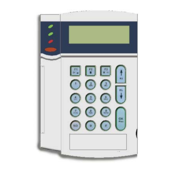
Five different panel types are available: the CS175, CS275, CS375, CS575 and CS875. In this manual they are known collectively as the CSx75. This manual describes a CSx75 installation using the CS5500, the menu driven keypad. The CS5500 allows you to program the system easily using a menu structure. - Page 10 • On if the system is connected to the mains and the battery is OK. • Flashes if the system has no battery or a low battery. Power (green) • Off if the system is not connected to the mains. •...
-
Page 11: Other Lcd And Led Keypads
When editing text and phone numbers: • Press # F1 to move to the first character or number. Hash • Press # F3 to move to the last character or number. • Press # to delete from the current position to the last character or number. Press the navigation keys to scroll through menu lists and options. -
Page 12: Designing The Csx75 System
3 modules 16 modules (CS375) 32 modules Keypads do not count as Keypads do not count as 32 modules (CS575) Keypads count as modules modules on the CS175 modules on the CS275 Keypads count as modules when on the CS875... -
Page 13: Parts Of The System
Input expander Expands the number of wired zones by 8 or 16 zones module The wired zone expanders can only be used with the CS375, CS575 and CS875. You can only expand the CS175 and CS275 by using a wireless receiver. - Page 14 Table 2-2: System modules Part number Part Purpose CS534 Audio (listen-in) Two-way audio (listen-in) communicator that allows the situation on module the premises to be monitored. CS7050 TCP/IP Module Dual microprocessor-controlled Internet/Intranet interface used to connect the CSx75 control panel to the OH Network Receiver. CS7501 ISDN Module Integrated services digital network dialler that allows digital data to be...
- Page 15 Table 2-4: Wireless Equipment Part Number 433 MHz 868 MHz Purpose Wireless Receiver RX8I4CA-pcb RX8W8CA-pcb RF 433 versions provide RX16I4CA-pcb RX16W8CA-pcb RF capability for 8, 16, or RX48I4CA-pcb RX32W8CA-pcb 48 wireless/RF components. RF868 versions provide RF capability for 8 or 16 or 32 wireless/RF components.
- Page 16 Table 2-4: Wireless Equipment Part Number 433 MHz 868 MHz Purpose Wireless door window RF320I4 RF300W8 Transmits events to the sensor RF310I4 RF300W8B control panel via the RF receiver. Wireless shock sensor RF620I4 Not available Transmits events to the RF620I4B control panel via the RF receiver.
- Page 17 CS875-575-375-275-175 Installers Manual with CS5500 keypad A.2.6...
-
Page 18: Installation Guidelines
Chapter 3: Installation guidelines 3.1 Mains power connection Use the mains connector terminal for connecting the mains supply. You can use a fixed cable or a flexible mains lead to an earthed mains outlet. If fixed wiring is used, insert a dedicated circuit breaker in the power distribution network. -
Page 19: Defaulting The Panel
shielded cable should be used and the cable should be connected to a GND terminal at the control panel end only. The remote bus cable is used for communication between the control panel and the keypads/expanders. The greatest care should be taken when installing this cable. Never split it into separate cables. Do not use cables with wires that are used for telephone connections or for switching, for example, flashing lights, sirens or relays. -
Page 20: Installing A Basic System
Chapter 4: Installing a basic system 4.1 Wiring zones 4.1.1 General The control unit inputs are set up as standard EOL (4K7) freely programmable zones. However, by programming the zones as dual loop, all control unit zone inputs can be programmed to give alarm and tamper indication on the same zone. -
Page 21: Cs575M/Cs875M (Large Metal Housing
The housing/enclosures covered in this manual are not suitable for every CSx75 model and may not be available in your country. Contact your local supplier to get more information on availability. 4.2.1 CS575M/CS875M (large metal housing) This large metal housing can be used with the CS375, CS575 and CS875. CS375/575/875 Open the box. - Page 22 Mount the CS507 output module or CS208 / CS216 input expander or CS7002 GSM module. Mount the pillars for a CS208 / CS216 input expander on the CS575/875 board. Mount the CS208 / CS216 input expander on the CS575/875 board.
-
Page 23: Cs275/Cs375/Cs575/Cs875 (Polycarbonate Housing
4.2.2 CS275/CS375/CS575/CS875 (polycarbonate housing) This polycarbonate housing can be used with the CS275, CS375, CS575and CS875. CS534 CS275/375/575/875 Unscrew the holding screw in the polycarbonate housing. Open the box. Lift off the lid of the box. Flip up the PCB mounting tray. - Page 24 Connect the CS534 listen-in module to the box. Flip down the PCB mounting tray. Attach the pillars for the CS535 voice module to the board. Attach the CS535 voice module to the board via the jumpers and pillars. Connect the CS534 listen-in module and CS535 voice module with the ribbon cable. Attach the pillars for the CS208 / CS216 input expander or CS507 output module to the board.
-
Page 25: Cs175M/Cs275M/Cs375M/Cs575Sm (Small Metal Housing
16. Wire the keypad bus for any other modules that are not in the card guides. 17. Connect the battery and power up the panel. 4.2.3 CS175M/CS275M/CS375M/CS575SM (small metal housing) This is a small metal housing that can be used with the CS175, CS275, CS375 and CS575. CS534 CS535... - Page 26 CS216 CS507 CS216 CS507 CS575/875 CS175/275/375/575 Add the pillars for the CS208 / CS216 input expander or CS507 output expander to the main board. Mount the CS208 / CS216 input expander or CS507 output expander. Wire the keypad bus for all modules. Check the relevant module chapter for wiring information. For information on mounting the CS7501 ISDN dialler, see chapter B-16 Setting up the CS7501.
-
Page 27: Installing The Keypad
4.3 Installing the keypad Remove the keypad door. Remove the bottom screw if fitted. Place a short length of the shaft of the screwdriver in the hollow of the door hinge. Twist the screwdriver carefully. The two parts of the keypad should separate. Lift up the lid. Mount the keypad on the wall using the mounting holes C. -
Page 28: Wiring Several Keypads Together
4.3.2 Wiring several keypads together The total cable length of wiring is restricted to 800 m. The chart below shows the wire gauge that should be used. These numbers are for one keypad at the end of the wire. When connecting more than one keypad to the end of the wire, a higher gauge wire is required. - Page 29 4.3.2.3 Star and multidrop network You can create a combination of a star and multidrop network. The following diagram shows how four keypads can be connected using both methods. CS875-575-375-275-175 Installers Manual with CS5500 keypad A.4.10...
-
Page 30: Wiring Sounders
4.4 Wiring sounders 4.4.1 Wiring a sounder with EOL protection Any zone can be used. It should be programmed as tamper and single EOL. AS500 4.4.1.1 CSX75 AS500 Beacon - hold off Tamper Piezo Siren - hold off Tamper Piezo +13.8 V Beacon Piezo... - Page 31 4.4.1.2 AS271 A resistor should be added between the COM and the Ext on the panel PCB. This resistor prevents the panel being constantly in a trouble condition. Both the internal and external sirens are supervised. CSX75 AS271 Tamper 0 V speaker Tamper 0 V beacon (AS271 only) +13.8 V...
-
Page 32: Wiring Fire Detectors
4.4.1.3 AS290/390 CSX75 AS290/390 4 Beacon Piezo 5 Tamper Piezo +13.8 V 6 Tamper Beacon Siren - hold off Beacon - hold off Cut jumpers 5 and 7 for negative hold-off on the sounder. Information on programming the sounders can be found in chapter B-2 Programming the control panel. 4.5 Wiring fire detectors In a 4-wire configuration, you can connect as many fire detectors, as long as you do not exceed the AUX power capacity of the panel. -
Page 33: 4-Wire Fire Detector (Cs275-375-575-875
4.5.1 4-wire fire detector (CS275-375-575-875) DB702 +DB721R DB702 +DB721R CS275 CS375 CS575 CS875 1 + Line in 4 NC (normally closed) 2 + Line out 5 COM 3 - Line 6 NO (normally open) 4.5.2 2-wire fire detector (CS275-375-575-875) DB701 +DB721R... -
Page 34: 4-Wire Fire Detector (Cs175
4.5.3 4-wire fire detector (CS175) DB702 +DB721R DB702 +DB721R CS175 1 + Line in 4 NC (normally closed) 2 + Line out 5 COM 3 - Line 6 NO (normally open) If you are using a CS175, you must program output 3 for the fire detector. Select Installer Menu>Control Panel>Outputs>Prog Outputs>Output 3>Event>Alarms>Fire Reset. -
Page 35: Wiring The Outputs
4.6 Wiring the outputs DATA AUX+ CS875 CS575 CS375 R1NC R1NO AUX+ OUT2 R3NC R3NO AUX+ OUT4 TAMPER TAMPER DATA AUX+ CS275 AUX+ OUT2 OUT3 AUX+ OUT4 TAMPER TAMPER DATA AUX+ OUT1 OUT2 CS175 AUX+ TAMPER 1A rated contacts. Relays are powered and switched from the panel. No external power is needed to switch the relays. -
Page 36: Control Unit Wiring Diagrams
4.7 Control unit wiring diagrams 4.7.1 CS175 EXPANSION BLACK LED 2 LED 3 Zones 1-4 External sounder Serial expansion Box tamper input Keypad bus Phone line connector Fire detector reset output Additional keypad bus connection Phone line communication LED Open collector 2 Lid tamper Open collector 1 Bus supervision LED... -
Page 37: Cs275
4.7.2 CS275 EXPANSION LED 2 BLACK LED 3 1 Zones 1-6 7 Open collector 1 C Serial expansion 2 Lid tamper 8 External sounder D Bus supervision LED 3 Box tamper input 9 Internal sounder E Full expansion port 4 Open collector 4 (2 wire smoke) A Keypad bus F Phone line connector 5 Open collector 3... -
Page 38: Cs375, Cs575 And Cs875
4.7.3 CS375, CS575 and CS875 EXPANSION LED 2 BLACK LED 3 1 Zones 1-8 Relay 1 Bus supervision LED 2 Lid tamper * External sounder Full expansion port 3 Box tamper input * Internal sounder Phone line connector 4 Open collector 4 (2 wire smoke) - Page 39 4.7.3.1 Inputs and outputs DATA Communication/Expander data (0101) (including keypad) AUX + Communication/Expander power (including keypad) Communication/Expander ground (including keypad) Internal bell power Ground External bell return R1NC Relay 1 (normally closed) R1NO Relay 1 (normally open) Relay 1 (ground) AUX + Power OUT 2...
-
Page 40: Programming The System
Chapter 5: Programming the system 5.1 Powering up the system When the CS5500 if powered up for the first time, the language, keypad defaults, partition and keypad must be set. These options must also be set each time a keypad is defaulted. •... -
Page 41: Selecting A Menu Option
5.4 Selecting a menu option • Press OK to select a menu option and move forward in the menu structure. • Press NO to reject a menu option and move backwards in the menu structure. • Press F1 to move through the second line of the LCD display, one word at a time, from right to left. •... -
Page 42: Changing Phone Numbers And Phone Prefixes
Press to decrease the current value by one. Press ## to clear the current value to 0. Press the number keys to enter the value. Press OK to accept the changes. If the new value is valid, the keypad beeps once to confirm the change and returns to the menu option. If the new value is invalid, the keypad beeps three times to reject the change and returns to the menu option. -
Page 43: Example
Navigate with the keys to the relevant menu option and press OK. Press OK to select the language you want to edit. The current text for the menu option is displayed, for example, Zone 2. Do one of the following: •... -
Page 44: Installer Message
The keypad beeps once to accept the change and returns to Word Library. 5.7.4 Installer message Up to four messages can be displayed on the LCD when the keypad is idle or when it times out from a menu. If you enable more than one message, the messages are shown in a continuous cycle. -
Page 45: Setting Up A Communicator
Chapter 6: Setting up a communicator 6.1 Reporting The CSx75 supports different modes of reporting events to multiple central stations. There are six phone numbers - each phone number has it own account code, protocol and events. The configured prefix is common to all six phone numbers. -
Page 46: Dual Reporting
Level 1 Level 2 Value State Events Phone Number 1 – Alarms Enabled Phone Number 1 – Alarm Restores Enabled Phone Number 1 – Tampers and Restores Enabled Phone Number 2 – Alarms Disabled Phone Number 2 – Alarm Restores Disabled Phone Number 2 –... - Page 47 Level 1 Level 2 Value State Events Phone Number 1 – Alarms Enabled Phone Number 1 – Alarm Restores Enabled Phone Number 1 – Tampers Disabled Phone Number 2 – Alarms Disabled Phone Number 2 – Alarm Restores Disabled Phone Number 2 – Tampers and Restores Enabled CS875-575-375-275-175 Installers Manual with CS5500 keypad A.6.3...
-
Page 48: Installing And Programming The Modules
Section B Installing and programming the modules 1 Enrolling modules ................................B-1-1 2 Programming the control panel ..........................B-2-1 3 Programming the current keypads ........................B-3-1 4 Programming the other keypads..........................B-4-1 5 Setting up the RF receivers ............................B-5-1 6 Setting up the CS208H / CS208 / CS216......................B-6-1 7 Setting up the CS507..............................B-7-1 8 Setting up the CS586..............................B-8-1 9 Setting up the CS534..............................B-9-1... -
Page 49: Enrolling Modules
Chapter 1: Enrolling modules Enrol Number of Modules To enroll and default the system modules, you must enable the advanced menu. Select Commands>Advanced Menu>Enabled and press OK. 1.1 Enrolling the system modules When you select the enrol modules process, new modules are enrolled on both the control panel and the keypad. The keypad must enrol modules in order to display the relevant menu options. -
Page 50: Programming The Control Panel
Chapter 2: Programming the control panel 2.1 Overview You must enroll and default the control panel before you begin to program the system. For more information on enrolling and defaulting, see chapter B-1 Enrolling modules. 2.2 Programming inputs Zones (1) Zone 1 Zone Type 2.1.1 2.1.1.1... -
Page 51: Defining A Zone
2.2.1 Defining a zone You must select the language in which to program the new name and also assign partitions to the zone. You can select the zone type and zone name for each new zone. The following steps explain how to select the zone type and zone name for a new zone. -
Page 52: Editing A Zone Type
2.2.3 Editing a zone type A zone type is a collection of characteristics. All the zones included in a particular zone type share the same characteristics. Each zone must belong to a zone type. There are 20 pre-defined zone types which you can edit. To edit a zone type, you must enable the advanced menu. -
Page 53: Programming Outputs
2.3 Programming outputs Prog Outputs 1 (<Event>) Event Alarms 2.2.1.1.1.1 2.2.1 2.2.1.1 2.2.1.1.1 Arm/Disarm 2.2.1.1.1.2 Outputs 2 - 4 Communications Same as above 2.2.1.1.1.3 Keypads 2.2.1.1.1.4 Sirens 2.2.1.1.1.5 Tamper/Trouble 2.2.1.1.1.6 Tests 2.2.1.1.1.7 Miscellaneous 2.2.1.1.1.8 Time Unit 2.2.1.1.2 Time 2.2.1.1.3 Partitions 2.2.1.1.4 Latched Attributes... -
Page 54: Configuring The Internal Siren
Table 2-1: Control panel output events Event Event Event Misc Keypads Alarms Any Bypass Keypad Fire Burglary Alarm Duress Keypad Medical Fire Alarm Code Entry (Note 1) Keypad Panic 24-hour Alarm Program Mode Keypad Tamper Trouble Alarm 49 * Keyfob Funct 1 Chime Tamper Alarm 50 *... -
Page 55: Programming The Keypad Sounder
Scroll to Keyswitch Arming>Yes and press OK. The keypad beeps once to confirm the change and returns to Keyswitch Arming. 2.3.3 Programming the keypad sounder You can specify conditions and/or events that activate the keypad sounder. To configure the sounder, you must enable the advanced menu. -
Page 56: Setting Communication Options
2.5 Setting communication options Phone Prefix Central Station 2.4.1 2.4.1.1 Phone Numbers Phone Number 1 Phone Number 2.4.1.2.1 2.4.1.2.1.1 2.4.1.2 Account Code 2.4.1.2.1.2 Phone Numbers 2 - 6 Protocol Same as above 2.4.1.2.1.3 Events Arm/Disarm/Alarm Alarms 2.4.1.2.1.4 2.4.1.2.1.4.1 2.4.1.2.1.4.1.1 Alarm Restores 2.4.1.2.1.4.1.2 Opening/Closings 2.4.1.2.1.4.1.3... -
Page 57: Defining Communication With A Central Station
The control panel can report to a central station after all or specified events. Communication between the control panel and the central station is monitored to ensure against damage or faults. The control panel can also communicate with up/download software when a download session has been established. To program control panel communciation options, select Installer Menu>Control Panel>Communications. -
Page 58: Enabling Reporting
2.5.4 Enabling reporting You must enable event reporting in the control panel and program the events and zone types for which reports are sent. You must specify the format of the report and, in the case of voice reports, you must map each event to a recorded message. -
Page 59: Configuring A Partition
The keypad beeps once to confirm the change and returns to Exit 1. 2.6.2 Configuring a partition You can set partition features including arming and bypassing options. You can also enable life safety keys for the partition keypads. The following example allows the system to be armed with a lost zone and enables the personal alarm combination keys so they activate a personal attack alarm when pressed. -
Page 60: Setting Timers
2.7.1 Setting timers You can set timers to control the duration of various system functions. The following example sets the internal siren timer to five minutes. When the siren starts ringing, the timer starts counting down. When the timer is finished, the siren automatically cuts out. -
Page 61: Programming The System To Work With A Home Automation System
X-10 home automation module is made through the CS507 output expander or the CS534 listen-in module RJ11 connectors. The on-board RS232 connector on the CS275, CS375, CS575 and CS875-575-375-275-175 Installers Manual with CS5500 keypad... -
Page 62: Enabling Broadcasts
CS875 can be used to connect to other home automation systems. Consult your local Aritech Support to obtain more information. Updated system information can be sent from the control panel to the home automation system in binary or ASCII format. The control panel can respond to requests sent by the home automation system and in turn can send commands to the home automation system. -
Page 63: Glossary
2.10 Glossary Location Term Definition Control Panel This groups all options relating to the central processing unit of the alarm system. The control panel monitors the detection devices and activates any number of signalling devices. Inputs A menu entry that groups options relating to all zones. 2.1.1 Zones An menu entry that groups zone options. - Page 64 Location Term Definition 2.1.3.1.1.7 Interior A zone type within the building that is bypassed when the system is armed in stay mode. 2.1.3.1.1.8 Entry Guard A zone type that reduces false alarms. If an armed entry guard zone is opened, the keypad sounder activates and the entry delay starts before creating an alarm.
- Page 65 Location Term Definition 2.1.3.1.4.1 Yelping Siren - Burglary A menu option that sounds a yelping siren when a burglary zone is activated. 2.1.3.1.4.2 Temporal Siren - Fire A menu option that sets whether a zone type activates a fire or a burglary siren.
- Page 66 Location Term Definition 2.2.1.1.2 Time Unit A menu option that specifies whether the outputs are timed in minutes or seconds. 2.2.1.1.3 Time A menu option that sets the length of time for which an output is activated. If it is set to 0, the output follows the event. 2.2.1.1.4 Partitions A menu entry that lists the partitions assigned to the selected output.
- Page 67 Location Term Definition 2.2.2.3 Output Signal Type A menu option that converts the internal siren to accept a speaker. The built-in 112db siren driver can be converted to a 1-amp voltage output. The siren can be 15 or 30 Watt maximum, with an impedance of 4, 8 or 16 ohms. 2.2.3 Keypads A menu option that groups keypad buzzer options.
- Page 68 Location Term Definition 2.3.2.3 Partitions A Codes menu entry that lists the partitions assigned to the selected code. The selected code can trigger an event on these partitions. 2.3.3 Duress Code A menu option that sets the duress code. A duress code disarms the system and activates a duress alarm.
- Page 69 Location Term Definition 2.4.1.2.1.4.2.1 Tampers and Restores A menu option that sends a report to the selected phone number when a tamper occurs. A report is also sent when the tamper is no longer active. 2.4.1.2.1.4.2.2 Zone Trouble and Restores A menu option that sends a report to the selected phone number when a zone trouble condition occurs.
- Page 70 Location Term Definition 2.4.1.5 Dialler Output Level A menu option that sets the volume of the output tone. The Dialler Output Level can only be used in combination with the stand-alone ISDN dialler TDA2001. 2.4.1.6 Dialler Abort Delay A menu option that creates a delay, programmed in seconds, in reporting an alarm to the central station.
- Page 71 Location Term Definition 2.3.2.8.3 Comms Settings A menu option that prevents the installer changing the communication settings (telephone numbers, account codes and so on). This option must be set using the up/download software. 2.4.2.8.4 Download Settings A menu option that prevents the installer changing the following download settings: Answer Machine Defeat Call Back Req’d...
- Page 72 Location Term Definition 2.4.4.2.1 Tamper/Trouble A menu entry that groups together the tamper and trouble events that are reported to the central station. 2.4.4.2.1.1 Box Tamper A menu option that enables the box tamper switch on the control panel. The CSx75 has an input for a normally closed tamper switch.
- Page 73 Location Term Definition 2.4.4.2.6 First to Open/Last to Close A menu option that sends a report to the central station stating when the system opened and closed. This option can only be used in a multi-partitioned system. A report is sent stating the first area opened. A log is then kept recording when the other areas opened and when they closed.
- Page 74 Location Term Definition 2.4.4.3.1.1.9 200Bd FSK Channel A menu option that sets the channel used by the selected zone, zone type or 2.4.4.3.2.1.4 event for 200Bd FSK protocol. The zones between 1 and 99 can be directed to 2.4.4.3.3.1.4 separate channels. The zones between 100 and 168 follow the 200Bd FSK 2.4.4.3.3.2.6 Channel as specified on the zone type.
- Page 75 Location Term Definition 2.4.4.3.3.7 RF Sensor Lost A menu entry that groups report codes sent to the central station when an RF sensor lost event occurs. 2.4.4.3.3.8 RF Low Battery A menu entry that specifies the code (SIA/ContactID/FastFormat/200Bd FSK) or voice channel to be used for RF Low Battery events. 2.4.4.3.4 Keypad A menu entry that groups the report codes sent to the central station for...
- Page 76 Location Term Definition 2.4.5.2 Features 2 A menu option that allows you to configure your own reporting protocol based on the options enabled. Partition Settings A menu entry that groups all partition settings. These settings include partition features, partition timers and so on. 2.5.1 Timers A menu entry that groups timer options.
- Page 77 Location Term Definition 2.5.2.3 Bypass To temporarily remove a zone from operation when arming the system. A menu entry that groups bypass options. 2.5.2.3.1 Auto Bypass A menu option that automatically bypasses interior follower zones if no exit is detected during the exit delay time. The exit is detected by the opening and closing of an entry/exit zone.
- Page 78 Location Term Definition 2.6.1.3.1 Internal Siren Timeout A menu option that sets the length of time the internal siren rings before automatically cutting out. This time can be between 0 and 255 minutes. When set to 0, the siren is active until a valid code is entered on the keypad. 2.6.1.3.2 External Siren Timeout A menu option that sets the length of time an external sounder/siren rings...
- Page 79 25 VA or 40/50 VA. Depending on the setting, the power supply of the CS275, CS375, CS575 and CS875 can deliver 0.5 A (25 VA setting) or 1 A (40/50VA setting) on the AUX terminals. If this is not sufficient, additional CS320 power modules can be used.
- Page 80 Location Term Definition 2.7.3.2 Closing/Autoarm A menu option that sets the time after which the partitions selected in Partitions Autoarming start to arm automatically. Users with arm only after closing rights can arm the partitions selected in Partitions Opening only after this time.
- Page 81 Location Term Definition 2.8.3.2 Misc Commands A menu entry that groups home automation commands. 2.8.3.2.1 X-10 Message A menu option that enables the control panel to respond to X-10 message commands sent by the home automation system. 2.8.3.2.2 Store Comms Event A menu command that allows a device connected to the serial port to send reports to the central station using the controls modem.
-
Page 82: Technical Specifications
Lead acid rechargeable 16 Ah 12 V nom. Battery Type and max. capacity (Polycarbonate Housing for CS275– CS375- Lead acid rechargeable 10 Ah 12 V nom. CS575-CS875) Battery Type and max. capacity (Small Metal Housing for CS175M– Lead acid rechargeable 7.2 Ah 12 V nom. - Page 83 General feature specifications Nr. of combination of codes From 9.999 (4 digits) to 99.999 (6 digits) End of line resistor (standard) 4,7 KOhm, 2% 0.25W End of line resistor (2 wire smoke) 560 Ohm, 2% 0.25W Loop Response Selectable 50 msec or 500 msec Built-in Siren Driver 2 tone ( Temporal and Yelp) On-board Outputs...
-
Page 84: Programming The Current Keypads
Chapter 3: Programming the current keypads 3.1 Overview Each keypad has a sounder and an LCD display that displays messages in a number of possible languages. Each keypad must be enrolled, defaulted to the country settings for the selected country and defaulted to the factory defaults before starting to program the system. -
Page 85: Multi-Area Mode
Navigate with the keys to Sounds>Beep on RF loss>Yes and press OK. The keypad beeps once to confirm the change and returns to Beep on RF loss. 3.3 Multi-area mode You can program a keypad to act as a single-area keypad or a multi-area keypad by default. A single-area keypad allows the user to arm one area only while a multi-area keypad allows the user to arm one or more areas. -
Page 86: Glossary
Scroll to Language 2 and press OK. Use the keys to select Français and press OK. The keypad returns to Set Languages. Repeat these steps to set other languages. For information on changing the user interface language or setting the keypad messages, see chapter 5. 3.7 Setting the keypad partition and keypad number When you first power up the keypad, you are prompted to set the language, the default country and the partition and keypad number for the current keypad. - Page 87 Location Term Definition 3.1.2.1 Silent Keypad A menu option that silences the keypad’s entry/exit sounder and chime only. 3.1.2.2 Ding Dong Chime A menu option that sets the sound a chime makes. It is either a ding dong or a beep.
- Page 88 Location Term Definition 3.4.2 To All Keypads A menu option that specifies that the current keypad settings are copied to all connected keypads. Text A menu entry that groups the language options of the current keypad. It allows the installer to set options such as zone name descriptors and user names. 3.5.1 Set Languages A menu option that selects the keypad language.
-
Page 89: Technical Specifications
3.9 Technical specifications 3.9.1 CS5006 LED keypad Power supply specifications ± 0.2V Power supply voltage 13.8V Consumption – Normal condition (Piezo Off) 78 mA at 13.8V ± 2% Consumption – Normal condition (Piezo On) 90 mA at 13.8V ± 2% Consumption –... -
Page 90: Cs5500 Menu Driven Keypad
3.9.3 CS5500 menu driven keypad Power supply specifications ± 2% Power supply voltage 13.8V Consumption – Normal condition (Piezo Off) 90 mA at 13.8V ± 2% Consumption – Normal condition (Piezo On) 100 mA at 13.8V ± 2% Consumption – Standby 7 mA at 13.8V ±... - Page 91 Chapter 4: Programming the other keypads Keypad 1 Model (1) Partition 1 4.1.1 4.1.1.1 Version 4.1.1.2 Partitions 2 - 8 Keypads 2 - 8 Default Settings Same as above Same as above 4.1.1.3 To program other keypads, select Installer Menu>Other Keypads and select the partition containing the keypad. You can view the keypad version and model and default the selected keypad.
-
Page 92: Setting Up The Rf Receivers
Chapter 5: Setting up the RF receivers 5.1 Overview You can add either an 868 Mhz or 433 Mhz wireless receiver to the CSx75. Adding a receiver module makes a CSx75 control panel compatible with wireless sensors and keychain touchpads or keyfobs. 5.1.1 Types of receivers Table 5-1: Types of receivers Type of Receiver... -
Page 93: Installing An Rf433 Mhz Receiver
5.2 Installing an RF433 Mhz receiver 7 Not used Processor Wireless communication LED 8 Antenna No function Keypad bus connection 9 DIP switches Bus supervision LED Lid tamper 5.2.1 Wiring an RF433 Mhz receiver Wire the RF433 Mhz receiver terminals 5 as follows. Table 5-2: RF433 Mhz receiver terminal connections Terminal Description... -
Page 94: Rf433 Mhz Receiver Status Conditions
Set the DIP switch 9 from Table 5-3: RF433 Mhz receiver DIP switches. Power up the RF433 Mhz receiver. Table 5-3: RF433 Mhz receiver DIP switches DIP switch 1-3 Module DIP switch 1-3 RF receiver Module settings receiver number settings number 32 (default) = ON... -
Page 95: Installing An Rf868 Mhz Receiver
5.3 Installing an RF868 Mhz receiver 1 Jumper setting 5 Wireless communication LED Jumper setting 2 Lid tamper 6 Keypad bus connection Processor 3 Eeprom 7 Not used DIP switches 4 Bus supervision LED 8 Antenna 5.3.1 Wiring an RF868 Mhz receiver Table 5-5: RF868 Mhz receiver terminal connections Terminal Description... -
Page 96: Rf868 Mhz Receiver Status Conditions
Some RX8W8, RX16W8 and RX32W8 receivers have DIP switch labels with On/Off rather than Open/Closed labels. In the table below you can find both references. The label on the receiver always refers to Open/Close (O/ Table 5-6: RF868 Mhz receiver DIP switches DIP switch 1-3 Module DIP switch 1-3... -
Page 97: Programming The Rf System
5.4 Programming the RF system RF Receiver 32 Start Zone 5.1.1 RF Receivers 33 - 39 Same as above Learn-in Mode Start Learning (1) Zone 1 5.1.2 5.1.2.1 5.1.2.1.1 Sequential Programming 5.1.2.2 Inputs Sensor 1 Enabled 5.1.3 5.1.3.1 5.1.3.1.1 Supervised 5.1.3.1.2 Sensors 2 - 168 Same as above... -
Page 98: Configuring Receiver Features
Scroll to Start Learning and press OK. Enter the zone number to start with. In this case, enter 9 to program the detectors in zones 9 and 10 and press Tamper the different detectors in sequence. To do this, you activate the sensor’s tamper switch. Table 5-8: Learning RF sensors explains how to activate each type of sensor. -
Page 99: Testing Wireless Sensors
5.5 Testing wireless sensors 5.5.1 RF433 Mhz system The RF433 Mhz system uses a last round count to provide an indication of the quality of the data reception. It displays the number of rounds of RF data received during the last transmission. The following example tests the last round count on sensors enrolled on RF receiver 33. -
Page 100: Glossary
5.7 Glossary Location Term Definition RF Receiver 32 An menu entry that groups all options for the selected RF receiver. An menu option that specifies the first zone number of zones on the RF 5.1.1 Start Zone receiver. An menu option that enables the mode in which a new wireless device is 5.1.2 Learn-in Mode enrolled on the system. - Page 101 Location Term Definition A menu option that makes the keyfob report as the zone that it is learned into. 5.1.4.2 Keyfob User ID When this option is disabled, all keyfobs report their open/closing reports as user 99. A menu option that reports a keyfob low battery condition. This option is available on the 868 Mhz RF Receiver only.
-
Page 102: Technical Specifications
5.8 Technical specifications 5.8.1 RF433 receivers: RX8i4-pcb, RX16i4-pcb, RX48i4-pcb Power supply specifications ± 2% Power supply voltage 13.8V Consumption 20 mA at 13.8V ± 2% Wireless Frequency 433 Mhz General feature specifications PCB Size Dimensions (width x height x depth) 110x81x25.4 mm Environmental Operating temperature... -
Page 103: Setting Up The Cs208H / Cs208 / Cs216
Chapter 6: Setting up the CS208H / CS208 / CS216 6.1 Overview The CS208H, CS208 and CS216 input expanders can provide extra wired zones for a CSx75 control panel. Each CS208H and CS208 input expander can provide up to 8 extra wired zones. Each CS216 input expander can provide up to 16 wired zones. - Page 104 Power up the CS208 / CS216 input expander Table 6-1: CS208 / CS216 input expander DIP switches Starting Module Starting Module switch setting zone number switch setting zone number number number = ON = OFF 6.2.2.1 DIP switch 6 (CS216 only) To disable the second group of 8 zones on the CS216 input expander, turn DIP switch 6 on.
-
Page 105: Wiring The Cs208 / Cs216 Input Expander
6.2.3 Wiring the CS208 / CS216 input expander To wire the CS208 / CS216 input expander, see Table 6-2: CS208 / CS216 input expander terminals. Any unused zones must have an EOL resistor across them, unless all 8 are disabled by DIP switch 6 (CS216 only). The CS208 / CS216 input expander is similar to the CS507 output expander. -
Page 106: Cs208H Input Expander
6.3 CS208H input expander The CS208H input expander comes in its own housing. The board is different to the CS208 input expander. 6.3.1 Installing the CS208H input expander Unscrew the screws to open the housing. Wire the terminals as shown. Replace the lid, making sure that the orientation is correct. -
Page 107: Setting The Dip Switches
6.3.3 Setting the DIP switches Power down the CS208H input expander. Decide the starting zone of each CS208H input expander. The starting zone of each zone expander must be on a boundary of 8 zones. To set the starting zone, set the DIP switches from Table 6-3: CS208H DIP switches. The 8 zones for this module begin from this starting zone number. -
Page 108: Wiring The Cs208H Input Expander
6.3.4 Wiring the CS208H input expander To wire the CS208H input expander, see Table 6-4: CS208H input expander terminals. Any unused zones must have an EOL resistor across them. Table 6-4: CS208H input expander terminals Terminal Description DATA Connect to the KP DATA terminal of the CSx75. Connect to the KP POS terminal of the CSx75. -
Page 109: Glossary
6.5 Glossary Location Term Definition CS208 / CS216 Input Expanders An expander board that increases the number of wired inputs that can be used for a particular zone. It has an optional tamper switch and a power isolator for use in a remote location. It cannot be used on the CS175 or CS275 control panel. -
Page 110: Setting Up The Cs507
Chapter 7: Setting up the CS507 7.1 Overview The CS507 output expander is an auxiliary module used to expand the output capabilities of the CSx75 control panel with the following functionality: • Microprocessor controlled two relay, five Open Collector expander. •... -
Page 111: Setting The Dip Switches
7.2.1 Setting the DIP switches Power down the CS507 output expander. Set the DIP switch according to Table 7-1: CS507 output expander DIP switches. Table 7-1: CS507 output expander DIP switches DIP switch setting Address Outputs DIP switch setting Address Outputs 33-39 9-15... - Page 112 An additional connector J1, (left middle), allows a direct bus connection to the controller. An additional cable is supplied with the panel in case you install the expander in the housing of the CSx75, and connects to J16 on the CS575. There are 2 ways of connecting the CS507 output expander module to the CSx75 controller: •...
-
Page 113: Programming The Cs507 Output Expander
7.3 Programming the CS507 output expander Output Exp 24 Outputs 1 (<Event>) Event 7.1.1.1.1 7.1.1 7.1.1.1 Alarms 7.1.1.1.1.1 Arm/Disarm Output Exps 25 - 31 Outputs 2 - 8 7.1.1.1.1.2 Same as above Same as above Communications 7.1.1.1.1.3 Keypads 7.1.1.1.1.4 Sirens 7.1.1.1.1.5 Tamper/Trouble 7.1.1.1.1.6... - Page 114 Table 7-3: CS507 output expander output events Event Event Event Tampers Misc Communications Mains Failure Any Bypass Listen-in Low Battery Duress Line Seizure Fire LED Code Entry Failed to communicate Fire Trouble Program Mode Telephone line fault Expander Trouble Keyfob Funct 1 Download Over-current Keyfob Funct 2...
-
Page 115: Setting Up Schedules
7.3.1 Setting up schedules You can set up a schedule to control the day and time at which the system automatically opens and closes or the days on which specific output events are active. You can also specify certain days on which the schedule is not active. -
Page 116: Glossary
7.4 Glossary Location Term Definition CS507 Output Expanders An expander board that increases the number of outputs that can be used with the control panel. A menu entry that groups CS507 output expander options. 7.1.1 Outputs A menu entry that groups options relating to programmable outputs. There are two types of outputs;... - Page 117 Location Term Definition 7.1.1.1.8 X-10 Address A menu option that sets the address of an X-10 device. This is a unique number assigned to an X-10 device. It consists of the module number and house code. The system uses this address to identify the device. 7.1.1.1.8.1 Module Number A menu option that sets the X-10 module number used to identify a particular...
-
Page 118: Technical Specifications
7.5 Technical specifications Power supply specifications Power supply voltage 13.8V ± 2% Consumption – No outputs active 10 mA at 13.8V ± 2% Consumption – All outputs active 25 mA at 13.8V ± 2% + current draw of any device attached. -
Page 119: Setting Up The Cs586
Chapter 8: Setting up the CS586 8.1 Overview The CS586 direct connect module is an optional device used to interface the up/download software directly to the control panel when the on board serial port is not available. The CS586 direct connect module has four programming memories. -
Page 120: Connecting The Cs586 To A Pc And A Panel
8.2.2 Connecting the CS586 to a PC and a panel Connect the CS586 direct connect module to the serial port of the PC and the panel as shown in the previous section. The black and red connectors can be connected to any 12V DC source and the green connector does not need to be connected. -
Page 121: Enabling Memory Transfer Using The Cs5500 Keypad
8.3.1 Enabling memory transfer using the CS5500 keypad The following example uses the CS5500 keypad to copy the control panel’s programming memory to the CS586 programming memory 2. It then copies programming information from the CS586 programming memory 3 to the control panel. -
Page 122: Glossary
Panel Type A menu option that displays panel type information currently stored in one of the four programming memory files in the direct connect module. Possible values are CS175, CS275, CS375, CS575 and CS875. 8.1.1.2 Panel to File A menu option that copies a panel’s programming to one of the programming memories in the direct connect module. -
Page 123: Setting Up The Cs534
Chapter 9: Setting up the CS534 9.1 Overview The CS534 listen-in module is a two-way audio and voice communicator for the CSx75 control panel. Once the control panel has communicated an alarm, the CS534 listen-in module allows a monitoring service operator to listen-in to a customer’s premises. -
Page 124: Wiring The Cs534 Listen-In Module
9.2.1 Wiring the CS534 listen-in module Table 9-1: CS534 terminal connections Terminal Description Connector on the left side. Connect positive side of microphone #A. Connect negative side of microphone #A. Connect positive side of microphone #B. Connect negative side of microphone #B. SPK+ SPK- Connect to the speaker(s). -
Page 125: Control Levels
The CS534 listen-in module sends a continuous indicator tone to the central station until the access code is received or the maximum number of attempts is exhausted. When a code is received, the indicator tone is silenced. The CS534 listen-in module waits for the access code to match. The reset [#] key may be used during PIN entry to clear the PIN buffer. -
Page 126: Tones
Table 9-2: CS534 control levels Level Output / relay control level (positive—turn Note: This feature requires X-10 Interface. Returns to the initial session settings when it is tripped. This includes the microphone selection and audio mode. 1 - 9 Turns the corresponding output/relay ON. A positive tone sounds. Level Status check Returns to the initial session settings when it is tripped. -
Page 127: Programming The Cs534 Listen-In Module
9.3 Programming the CS534 listen-in module Feature Select Mode 9.1.1 Listen-in Only 9.1.2 Speaker Lockout 9.1.3 Mic A at Startup 9.1.4 Mic B at Startup 9.1.5 Answer Machine Defeat 9.1.6 Status Check 9.1.7 Arming/Disarming 9.1.8 Call Back Code Line Hold Digit Wrong PIN Digit Entries Rings to Answer Timers... -
Page 128: Glossary
Navigate with the keys to CS534 Listen-in Module>Volumes and press OK. Scroll to High Gain Listen In>4 and press OK. The keypad beeps once to accept the change and returns to High Gain Listen In. 9.3.4 Assigning X-10 devices The CS534 listen-in module can activate X-10 devices over the telephone. The following example assigns device 1 (module number 5, house code L) to the CS534 listen-in module. - Page 129 Location Term Definition Call Back Code A menu option that specifies the code that starts a listen-in session when the panel is in call back mode. This code can be a maximum of six digits long. Line Hold Digit A menu option that specifies the digit that starts a two-way session when the control panel is in line hold mode.
-
Page 130: Technical Specifications
Location Term Definition 9.8.1.1 House Code A menu option that sets the code used to identify a particular premises. It is necessary in case any neighbouring premises also has an X-10 home automation system. More information on the X-10 home automation system can be found at www.x-10europe.com. -
Page 131: Setting Up The Cs320
Chapter 10: Setting up the CS320 10.1 Overview The CS320 is an auxiliary power module that can be used with the CSx75 range of panels. It has three programmable outputs and one dedicated sounder output. You can use up to eight CS320 auxiliary power modules to supply 32 outputs for the panel, 24 of which are programmable and eight are dedicated sounder outputs. -
Page 132: Wiring The Cs320 Auxiliary Power Module
10.2.1 Wiring the CS320 auxiliary power module Table 10-1: CS320 auxiliary power module terminal connections Terminal Description Connect to the KP DATA terminal of the CSx75. This terminal is the incoming data- DATA signalling terminal to the CS320 auxiliary power module. Connect to the KP COM terminal of the CSx75. -
Page 133: Enrolling The Cs320 Auxiliary Power Module
10.2.3 Enrolling the CS320 auxiliary power module Set DIP switches 1-3 to the correct address. Select Enrol Modules>Enrol and press OK. to enrol the CS320 auxiliary power module. The enrolling process takes about 12 seconds. User codes are not accepted during the enrolling process. 10.3 Programming the CS320 auxiliary power module Power Module 84 Outputs... -
Page 134: Configuring Features
Table 10-3: CS320 power module output events Event Event Event Alarms Arm/disarm Misc Alarm Memory Armed Code Entry Disarmed Program Mode Tests Dyn Battery Test Ready to Arm Always On Entry Tampers Keypads Fire LED Exit Keypad Fire Smoke Det Reset Entry or Exit Keypad Medical Over-current... -
Page 135: Glossary
10.4 Glossary Location Term Definition A module that provides an additional power supply if the system is using more CS320 Power Modules peripherals than can be serviced by the panel power supply. 10.1 Power Module 84 A menu entry that groups all options for the selected power module. A menu entry that groups options relating to programmable outputs. - Page 136 Location Term Definition A menu option that sets the length of time between detecting a mains failure on 10.1.3.1 Mains Delay Time a power module and sending a report to the central station. The restore event is sent four minutes after the mains is restored. A menu option that enables a test to determine whether the battery is 10.1.3.2 Battery Test...
-
Page 137: Technical Specifications
10.5 Technical specifications Mains power specifications Mains Input Voltage (25VA Transfo) 230V ~ - 50Hz ± 10% - 25VA Mains Input Voltage (40VA Transfo) 230V ~ - 50Hz ± 10% - 40VA Current consumption at 230V~ (25 VA) 0.108 A Current consumption at 230V~ (40 VA) 0.173 A Main board supply voltage... -
Page 138: Setting Up The Cs535
Chapter 11: Setting up the CS535 11.1 Overview The CS535 voice module reports alarm events to designated phone numbers using pre-recorded voice messages. You record the voice messages using a normal analog telephone. When an alarm event occurs, the control panel establishes a telephone connection with a specified phone number and informs the CS535 voice module to report configured events. -
Page 139: Programming The Cs535 Voice Module
11.3 Programming the CS535 voice module Recording All in Sequence 11.1 11.1.1 Leader Message 11.1.2 Single Event Message Message 1 11.1.3 11.1.3.1 Multiple Event Messages 11.1.4 Messages 2 - 15 Same as above 11.1.5 Address Message 11.1.6 Kiss Off Message All in Sequence Playback 11.2.1... -
Page 140: Playing Back Messages
If you a recording a single message, press the recording/playback button to stop recording. The message is played back. If you are satisfied with the message, press the recording/playback button to record the next message. Do not start recording the next message while the recording/playback LED is lit. To re-record a message, press the recording/playback button twice in quick succession and re-record the message. -
Page 141: Glossary
11.4 Glossary Location Term Definition CS535 Voice Module A module used to send pre-recorded voice messages when activated. A menu entry that groups recording options for messages sent by the voice Recording module. A menu command that records all voice messages in sequence. The sequence 11.1.1 All in Sequence is: Leader message;... -
Page 142: Technical Specifications
11.5 Technical specifications Power supply specifications Power supply voltage 13.8V ± 2% Consumption – Not in session 30 mA at 13.8V ± 2% ± 2% Consumption – 2 way listen-in in session 100 mA at 13.8V General feature specifications PCB size Dimensions (width x height x depth) 57x100x20 mm Environmental... -
Page 143: Setting Up The Cs1700
The LEDs can be programmed to follow the output and/or the armed or ready status of the system. It has an optional optical tamper switch. The CS1700 proximity reader can be used only with the CS375, CS575 and CS875. -
Page 144: Wiring The Cs1700 Proximity Reader
12.2.1 Wiring the CS1700 proximity reader Table 12-1: CS1700 proximity reader terminal connections Wire Description Green (data) Connect to the control panel DATA terminal. This wire is the data-signalling terminal to all the devices on the bus. Black (com) Connect to the control panel COMMON terminal. This wire supplies the common side of the power to the CS1700 proximity reader. -
Page 145: Programming The Cs1700 Proximity Reader
12.3 Programming the CS1700 proximity reader Prox Reader 113 Badge Functions Single Badge (1 Beep) Send Code Entry Function 12.1 12.1.1 12.1.1.1 12.1.1.1.1 Double Badge (2 Beeps) Arm Away 12.1.1.2 12.1.1.1.2 Prox Reader 114 - 127 Badge Hold (3 Beeps) Arm Stay Same as above 12.1.1.3... -
Page 146: Configuring X-10 Functions
The keypad beeps once to accept the change and returns to Keyfob Funct 1. 12.3.2 Configuring X-10 functions You can program the X-10 function that is performed when a card is scanned. The following example enables X- 10 device 4 (module number 6, house code B) for the double badge action on proximity reader 113. To activate the double badge action, you must set the scan time. - Page 147 Scroll to Feature Select>User Card Programming>Enabled and press OK. The keypad beeps once to accept the change and returns to User Card Programming. Enter a master user code to enter the user menu. Choose from one of the procedures outlined below. Task Steps Add one card...
-
Page 148: Glossary
12.4 Glossary Location Term Definition CS1700 Proximity Readers A proximity card reader/door control module that can be programmed to control access in any or all areas. 12.1 Prox Reader 113 A menu entry that groups all options for the selected proximity reader. 12.1.1 Badge Functions A menu entry that groups the functions activated by Single Badge, Double... - Page 149 Location Term Definition 12.1.2.2 House Code A menu option that sets the code used to identify a particular premises. It is necessary in case any neighbouring premises also has an X-10 home automation system. More information on the X-10 home automation system can be found at www.x-10europe.com.
- Page 150 Location Term Definition 12.1.4.6 Access Without RTE A menu entry that enables a user to open the door without a Request To Exit (RTE). 12.1.4.7 Log Forced Entry A menu option that records a force entry event in the event log. 12.1.4.8 Output Schedule Selection A menu option that selects the schedule that is used by the selected proximity...
-
Page 151: Technical Specifications
Location Term Definition 12.1.8.1.1 Opening A menu option that sets the time at which the selected schedule enters the open state. 12.1.8.1.2 Closing A menu option that sets the time at which the selected schedule enters the closed state. 12.1.8.1.3 Active A menu option that specifies the days of the week that the selected schedule is active. -
Page 152: Setting Up The Cs7002
Chapter 13: Setting up the CS7002 13.1 Overview The CS7002 is the GPRS module that can be added to a CSX75 range of panel. The CS7002 GPRS module features include • Wireless event reporting • Four programmable report destinations • Selectable reportable events from eight partitions •... -
Page 153: Installing The Cs7002 Gprs Module
13.2 Installing the CS7002 GPRS module BUS COM BUS COM SIM ERR GPRS ACTIVE REPORTING PSU ERR GSM IN USE 7 Battery connectors for main panel battery leads VVMiQ connector SIM card holder Remote header connector for CS534/535 GPRS modem Header connector for main panel Antenna Connector LEDs... -
Page 154: Inserting The Sim Card
13.2.2 Inserting the SIM card Power down the system. Open the SIM card holder by sliding back the metal clip and lifting the holder. Slide the SIM card into the holder with the contacts (gold pads) facing the circuit board and the angled corner facing out. -
Page 155: Programming The Cs7002 Gprs Module
13.3 Programming the CS7002 GPRS module Reporting Report Control (1) Report 1 13.1.1.1.1 Destination 13.1 13.1.1 13.1.1.1 13.1.1.1.2 Backup Destination Reports 2 - 6 Same as above Events Arm/Disarm/Alarm Alarms 13.1.1.1.3 13.1.1.1.3.1 13.1.1.1.3.1.1 Alarm Restores 13.1.1.1.3.1.2 Opening/Closings 13.1.1.1.3.1.3 Zone Bypass and Restores 13.1.1.1.3.1.4 Tamper/Trouble Tampers and Restores... -
Page 156: Reporting
ranges from 0-31, with 99 as unknown. If an RSSI reading is not satisfactory, move the antenna to get a better reception. The following steps explain how to read the RSSI value. Navigate with the keys to CS7002 GPRS module>Options>GSM>RSSI Value and press OK. Note the RSSI reading. -
Page 157: Using Upload/Download
13.3.2.5 Control panel/CS7002 as backup for CS7002 Backup reports are sent when the CS7002 fails to send primary reports. Backup reports can be sent by another report control on the module or by another device on the system. 13.3.2.6 CS7002 as backup •... -
Page 158: Glossary
13.4 Glossary Location Term Definition CS7002 GPRS Module A module that operates as a GPRS and GSM communications module for reporting and upload/download. 13.1 Reporting A menu entry that groups reporting options. 13.1.1 Report Control A block of reporting data that contains configurations to format selected events into one or more messages according to pre-configured settings and send them to specified destinations. - Page 159 Location Term Definition 13.1.1.1.3.3 Power A menu entry that groups the power events that are reported to the selected report control. 13.1.1.1.3.3.1 Power Trouble and Restores A menu option that reports mains failure, mains restore, low battery and low battery restore events to the selected phone number, report control, receiver or email account.
- Page 160 Location Term Definition 13.1.3 SMS Reporting A menu entry that groups SMS reporting options. 13.1.3.1.1 Phone Number A menu option that sets the phone number to which SMS reports are sent. 13.1.3.1.2 Account Code A menu option that specifies the unique code sent from the modem in the control panel or dialler to the selected report control.
- Page 161 Location Term Definition 13.2.1.2 GPRS General Packet Radio Service. A global standard for wireless communications. It supports a range of bandwidths and can transmit and receive both small bursts and large amounts of data. 13.2.2 Phone Number A menu option that sets the phone number of the PC running the upload/ download software.
- Page 162 Location Term Definition 13.3.1.5 Bit Error Rate A menu option that displays the current Bit Error Rate (BER). The BER value is periodically updated when the module is logged into the network. This information is used for verification purposes only. BER values range from 0% to 7%, with 99 as unknown.
- Page 163 Location Term Definition 13.3.3.6.1 TCP/IP Alarm Port A menu option that configures the number of the TCP/IP port to which polling and alarms are reported. The default is 9999 and under normal circumstances should not be changed. 13.3.3.6.2 U/D Port A menu option that configures the number of the port used for upload/ download.
-
Page 164: Technical Specifications
13.5 Technical specifications Power supply specifications Power supply voltage ± 2% Consumption - Standby 30 mA at 12V ± 2% Consumption – Maximum via battery leads 2A at 12V ± 2% General feature specifications PCB Size Dimensions (width x height x depth) 97x102x24 mm Environmental Operating temperature... -
Page 165: Reserved
Chapter 14: Reserved CS875-575-375-275-175 Installers Manual with CS5500 keypad B.14.1... -
Page 166: Setting Up The Cs7050
Chapter 15: Setting up the CS7050 15.1 Overview The CS7050 TCP/IP module is a dual microprocessor-controlled Internet/Intranet interface used to connect the CSx75 control panel to the OH Network Receiver. This interface allows any or all events from the CSx75 to be reported over the network. -
Page 167: Wiring The Cs7050 Tcp/Ip Module
15.2.1 Wiring the CS7050 TCP/IP module Table 15-1: CS7050 TCP/IP module terminal connections Terminal Description Connect to the panel bus Aux+. Connect to the panel bus COM terminal. DATA Connect to the panel bus DATA terminal. Connect the Ethernet Jack J16 (10BT) to a 10BT Ethernet capable hub, router or gateway. Do not use a CASCADE or X port in crossover mode. -
Page 168: Programming The Cs7050 Tcp/Ip Module
15.3 Programming the CS7050 TCP/IP module TCP/IP Reporting 1 Receiver (1) IP Address 15.1 15.1.1 15.1.1.1 Receiver 2 Same as above Events Arm/Disarm/Alarm Alarms 15.1.1.2 15.1.1.2.1 15.1.1.2.1.1 Alarm Restores 15.1.1.2.1.2 Opening/Closings 15.1.1.2.1.3 Zone Bypass and Restores 15.1.1.2.1.4 Tamper/Trouble Tampers and Restores 15.1.1.2.2.1 15.1.1.2.2 Zone Trouble and Restores... -
Page 169: Configuring Tcp/Ip Reporting
15.3.1 Configuring TCP/IP reporting The CS7050 TCP/IP module can report to two receivers. You can configure the events to be reported, the reporting format and the reporting connection parameters. The following example uses TCP/IP reporting to send primary reports for tamper events occurring in partition 1 to receiver 1 (IP address 122.168.1.1). Navigate with the keys to CS7050 TCP/IP Module>TCP/IP Reporting>Receiver (1) and press OK. -
Page 170: Configuring Reporting Options
10. Navigate with the keys to Options>Reporting>Report Format and select the format relevant for your central station receiver. 11. The keypad beeps once to accept the change and returns to Report Format. 12. Navigate with the keys to E-mail Reporting>E-mail Server>Domain Name and press OK. 13. - Page 171 Navigate with the keys to Options>Network>Port Numbers and press OK. 10. Scroll to TCP/IP Alarm Port and press OK. 11. Enter the number of the port and press OK. 12. The keypad beeps once to accept the change and returns to TCP/IP Alarm Port. CS875-575-375-275-175 Installers Manual with CS5500 keypad B.15.6...
-
Page 172: Glossary
15.4 Glossary Location Term Definition A module that operates as an Ethernet communications module for reporting CS7050 TCP/IP Module and upload/download. 15.1 TCP/IP Reporting A menu entry that groups TCP/IP reporting options. 15.1.1.1 IP Address A menu option that configures the address of the selected TCP/IP receiver. A menu entry that contains all configurable events for each receiver or email account. - Page 173 Location Term Definition A menu entry that groups the communication events that are reported to the 15.1.1.2.4 Communications selected receiver. A menu option that reports a fail to communicate event to the selected report 15.1.1.2.4.1 Fail to Communicate control. A menu option that sends a test report to the selected receiver. The units can 15.1.1.2.4.2 Test Reports be set in days or hours.
- Page 174 Location Term Definition A menu option that sends a report to the selected email account when a siren 15.2.2.1.2.2.4 Siren/Phone Faults and Restores or phone fault occurs. A restore report is sent when the fault is fixed. A menu option that sends a report to the selected email account when an RF 15.2.2.1.2.2.5 RF Sensor Lost and Restores sensor is missing.
- Page 175 Location Term Definition A menu option that allows an upload/download session between the module 15.4.1 Site Initiated and the PC to be initiated from a keypad. A menu option that allows an upload/download session between the module and the PC to be initiated by the PC. The PC dials into the module. You must 15.4.2 Remote Initiated dial the data phone number to dial into the GSM for upload/download.
-
Page 176: Technical Specifications
Location Term Definition A menu option that configures the subnet mask. This is typically 255.255.255.0. Contact the network administrator to confirm. All IP addresses 15.7.2.4 Subnet Mask up to and including the local gateway must be allowed. When using cable modem/DSL, this mask is the same as that used by the PC. -
Page 177: Setting Up The Cs7501
Chapter 16: Setting up the CS7501 16.1 Overview The CS7501 ISDN (integrated services digital network) dialler allows digital data to be sent over a standard phone line. It supports reporting over the B and D channels on ISDN. 16.2 Installing the CS7501 ISDN dialler JP2/3 Part Purpose... -
Page 178: Led Indicators
Red LED Panel communication status. 16.2.1 LED indicators Status Description No activity. Green LED B channel The CS7501 ISDN connection is in use. reporting Flashing The CS7501 is between calls or trying different destinations. The CS7501 has no connection with the central station. Green LED D channel The CS7501 is making a connection to the central station or busy with... - Page 179 Connect the DATA, COM and POS bus connections on the CS7501 to the keypad bus Connect the ISDN connections via the RJ45 connector. Plug the cable between the CS7501 and the panel. Ensure that the colour of the cable matches at each end. Cables: Brown - Blue - Orange - Green.
- Page 180 The CS7501 cannot be used with a CS535 voice module. However you can install a CS534 audio module using a ribbon cable as shown above. The coloured side of the ribbon cable should be on the lefthand side. Place the CS534 under the tray in the panel box. The CS534 is mounted below the panel pcb. Lift the panel pcb and mount the CS534.
- Page 181 Connect the following: • Connect the COM of the panel (A) to the COM of the ISDN dialler connection (B). • Connect the battery COM cable of the panel (C) to the COM of the battery (D). § • Connect the red POS Male connector (E) f rom the ISDN dialler (F) to the battery 12V connector of the panel (G).§...
-
Page 182: Wiring The Battery Leads
The red LED flashes when the CS7501 is powered up. 16.2.3 Wiring the battery leads The battery leads should be wired to the panel battery as follows: Connect the COM of the panel to the COM of the ISDN dialler connection. Connect the battery COM cable of the panel to the COM of the battery. -
Page 183: Programming The Cs7501 Isdn Dialler
16.3 Programming the CS7501 ISDN dialler Reporting Phone Numbers Phone Number (1) 16.1.1.1.1 Phone Number 16.1 16.1.1 16.1.1.1 16.1.1.1.2 Account Code Phone Number 2-4 Protocol Same as above 16.1.1.1.3 Backup Control Dial Attempts 16.1.1.1.4 16.1.1.1.4.1 Dial Sequence 16.1.1.1.4.2 Version 3 only Events Arm/Disarm/Alarm Alarms... -
Page 184: Configuring Al2 Supervised Isdn Connection
The keypad beeps once to accept the change and returns to Phone Number. Scroll to Account Code and press OK. Enter 445566 and press OK. The keypad beeps once to accept the change and returns to Account Code Scroll to Protocol>SIA and press OK. The keypad beeps once to accept the change and returns to Protocol. -
Page 185: Glossary
16.3.3.1 Time synchronisation The CS7501 automatically corrects the time and date on the panel when the difference is more then 5 minutes between the panel time and ISDN network. This is done on every communication with the B-channel. 16.3.3.2 Call back The panel is set up to call back the central station in order to initiate an upload/download session. - Page 186 Location Term Definition 16.1.1.1.2 Account Code A menu option that specifies the unique code sent from the modem in the control panel or dialler to the selected phone number. This code is used to identify and charge the user. Separate account codes can be set up for each phone number and each partition.
- Page 187 Location Term Definition 16.1.1.1.5.3.2 Aux Overcurrent and Restores A menu option that sends a report to the selected phone number when too much current is detected. A restore report is also sent when the overcurrent condition is fixed. 16.1.1.1.5.4 Communications A menu entry that groups together the communication events that are reported to the selected phone number.
- Page 188 Location Term Definition 16.3.1.1 Connection Type A menu option that specifies the type of ISDN connection. You can choose point to point or point to multipoint. 16.3.1.2 MSN Phone Number Multiple Subscriber Number. You can have more then 1 telephone number on a single ISDN connection.
-
Page 189: Technical Specifications
16.5 Technical specifications Power supply specifications Power supply voltage ± 2% Consumption - Standby 30 mA at 12V ± 2% Consumption – Maximum via battery leads 2A at 12V ± 2% General feature specifications PCB Size Dimensions (width x height x depth) 150x80x24 mm Environmental Operating temperature... -
Page 190: Reading The Event Log
Chapter 17: Reading the event log 17.1 Overview 17.1 Alarm Memory 17.2 Reset Smoke Detector Service Check 17.3 17.4 Do Self Test Event Log 17.5 17.6 X-10 Devices 17.7 Advanced Menu 17.8 Zone Status 17.9 Device/Location Programming The event log displays the details of all the events that occur from when you turn the system on. A maximum of 512 events are held in the event log. -
Page 191: Event Log Events
17.2 Event log events Table 17-2: Event list Event message Explanation Alarm An alarm has been tripped. Alarm Restore See Alarm event message. Autotest An autotest message was sent to the central station. B-Alarm A full alarm on a B zone type that is considered a burglary alarm. Box Tamper A box tamper. - Page 192 Table 17-2: Event list Event message Explanation Fire Restore See Fire event message. First Open The time at which the first area was opened. Keypad Tamper A keypad tamper. Last Close The time at which the last area was closed. Late Close A user disarmed the system after the closing time specified in the panel schedules.
-
Page 193: Glossary
Table 17-2: Event list Event message Explanation Siren Tamper Restore See Siren Tamper event message. Start Download The start of an up/download. Start Prog Start programming. The installer entered programming mode. Tamper A tamper. Tamper Restore See Tamper event message. Telephone Fault Telephone line faults. - Page 194 Location Term Definition 17.5 Event Log A menu command that is used to view the event log. The event log is a list of events that occur in the system, regardless of the armed state of the system. They are held in a sequential event buffer with a time and date stamp. When the log is full, it overwrites the oldest entries with new data.
-
Page 195: Programming With The Udx75 Software
Chapter 18: Programming with the UDx75 software 18.1 Other methods of programming You can program the system using the CS5500 keypad or the UDx75 software. This software allows you to download the programming information on the control panel to the computer running the UDx75 software, change it and upload the changes from the computer to the panel. -
Page 196: Programming With Upload/Download Software
A message box opens saying Initializing modem. The computer connects to the panel. When you are finished uploading or downloading, select Download>Disconnect or click the Disconnect icon. 18.3 Programming with upload/download software Downloading allows you to read the existing programming data or the event log from the control panel. Uploading allows you to send programming data, that you have set up using the UDx75 software, from the computer to the control panel. -
Page 197: Programming Tasks
18.3.1 Programming tasks You can perform all available programming tasks using the UDx75 software. Table 18-2: UDx75 menu paths shows the UDx75 menu path for each task. Table 18-2: UDx75 menu paths Task UDx75 menu option Adding customer notes View>Customers>Notes Adding operators Program>Setup>Add/Change operators Backing up the database... - Page 198 Table 18-2: UDx75 menu paths Task UDx75 menu option Printing an operator list Program>Print preview>Operator list Printing customer notes Program>Print preview>Notes Printing the event log Program>Print preview>Event log Programming the CS1700 Expanders>CS1700>1 Programming the CS208/CS216 View>Control panel (Zones tab) Programming the CS320 Expanders>CS320>1 Programming the CS507 Expanders>CS507>1...
- Page 199 Table 18-2: UDx75 menu paths Task UDx75 menu option Viewing the auto answer failures View>Customers>Auto answer failures Viewing the control panel settings View>Control panel Viewing the event log Download>Event log>Read entire log Viewing the keypad status View>Keypad status CS875-575-375-275-175 Installers Manual with CS5500 keypad B.18.5...
-
Page 200: Section C
Section C Reference 1 Appendices ..................................C-1-1... -
Page 201: Appendix 1: Reporting Fixed Codes In Contact Id Or Sia
Chapter 1: Appendices 1.1 Appendix 1: Reporting fixed codes in Contact ID or SIA Table 1-1: Event codes lists the event codes sent for different reports (if enabled) when using Contact ID or SIA formats. The numbers in brackets following the event is the number that is reported as the zone number. If there are no parentheses, the zone is 0. -
Page 202: Appendix 2: Overview Of Module Numbers
1.2 Appendix 2: Overview of module numbers Every keypad, expansion module and wireless receiver module has a module number. Module Module number CSx75 CS534 Two-way Listen-In CS535 CS7002 CS7050 CS7501 1.2.1 CS1700 door swipe module Table 1-2: CS1700 module numbers Learn-in sequence Module number Learn-in sequence... -
Page 203: Appendix 3: Communicator Formats
1.3 Appendix 3: Communicator formats One of several communicator formats can be used to transmit to the receiver connected to phone number 1. Consult the instructions for your central station receiver to determine which format is compatible. Table 1-4: Communicator formats lists the selectable communication formats. Table 1-4: Communicator formats Format Description Contact ID... - Page 204 Table 1-5: Service messages Message Definition Action Control The control panel tried to send a message to the Ensure that the phone line is connected properly. Use a test Fail to Comm. central station but failed. phone to check that the phone service is available. Ensure that the central station phone number, account and protocol options are correct.
- Page 205 Table 1-5: Service messages Message Definition Action Lost The system has not received Ensure that the wireless zone module is receiving power and has RF sensor transmissions for a not been tampered with. Repair any faults. long period of time. Depending on how the system is programmed, this condition activates a service report.
-
Page 206: Appendix 5: Tasks Summary
1.5 Appendix 5: Tasks summary Table 1-6: System tasks Task Installer Master user User No code Condition* Adjusting the LCD contrast ¸ Answer an up/download call ¸ ¸ ¸ Arm and disarm the system ¸ If authority allows. Bypass a zone If authority allows. - Page 207 B- 3- 7 Communicator formats specifications A- 2- 1 C- 1- 1 A- 1- 1 A- 2- 1 Contact ID CS575 A- 4- 17 A- 4- 20 Control panel input and outputs B- 2- 7 A- 4- 19 communication wiring...
- Page 208 Programming mode A- 4- 17 B- 12- 1 CS175 Proximity card reader A- 4- 18 CS275 A- 4- 17 A- 4- 20 CS575 Report A- 4- 20 A- 2- 1 CS875 formats A- 6- 1 Installer Reporting B- 2- 6...
- Page 209 B- 2- 11 RF868 timers B- 5- 4 DIP switches B- 5- 3 B- 15- 4 installing TCP/IP reporting B- 5- 5 A- 5- 3 LEDs Text editor B- 5- 11 specifications B- 5- 8 B- 2- 8 B- 15- 3 B- 18- 1 B- 18- 3 testing...
Need help?
Do you have a question about the CS575 and is the answer not in the manual?
Questions and answers