GE Security Simon XT Installation Manual
Hide thumbs
Also See for Simon XT:
- User manual (60 pages) ,
- Quick operation manual (4 pages) ,
- User manual (2 pages)
Table of Contents
Troubleshooting

Subscribe to Our Youtube Channel
Related Manuals for GE Security Simon XT


Summary of Contents for GE Security Simon XT
-
Page 1: Installation Manual
Simon XT Installation Manual... - Page 2 Software. 1. Definitions. The following definitions apply to this document: a. “GE SECURITY”, with respect to title to or warranty of the Software, means GE Security Inc., a Delaware corporation. b. “Software” mean the executable software or firmware programs and accompanying...
- Page 3 Software. 5. Limited warranty. GE SECURITY warrants that for one (1) year from the date of delivery of the Licensed Product (Software Warranty Period), the functions contained in the Software will be fit for their intended purpose as described in the applicable Documentation from GE SECURITY, and will conform in all material respects to the specifications stated in such Documentation.
- Page 4 Simon XT Installation Manual Reorient or relocate the receiving antenna. Increase the separation between the equipment and receiver. Connect the affected equipment and the panel receiver to separate outlets, on different branch circuits. Consult the dealer or an experienced radio/TV technician for help.
-
Page 5: Table Of Contents
Contents Tables..................vii Preface . - Page 6 Simon XT Installation Manual Chapter 4. Programming ............29 Programming overview .
-
Page 7: Tables
Sensor group characteristics................................. 7 Table 5. Sensor assignments/locations..............................9 Table 6. System programming menu options............................11 Table 7. Simon XT panel keys and features ............................31 Table 8. Simon XT menu structure................................32 Table 9. Simon XT programming codes ..............................35 Table 10. Access codes.......................................35 Table 11. - Page 8 Simon XT Installation Manual...
-
Page 9: Preface
Preface This is the GE Simon XT Installation Manual. This document includes an overview of the product and detailed instructions explaining: • how to install; and • how to set up the product for customer use. There is also information describing how to contact technical support if you have questions or concerns. - Page 10 Simon XT Installation Manual...
-
Page 11: Chapter 1 Introduction
Chapter 1 Introduction This chapter provides an overview of the system and an outline of the steps you need to perform before you begin installing and configuring your security system. In this chapter: Product overview ..........2 System components . -
Page 12: Product Overview
The system (Figure 1) has three types of components: • Self-contained control panel • Devices that report to the panel • Devices that respond to commands from the panel Figure 1. Simon XT system Door/window sensor PIR motion sensor Keyfob Smoke detector Remote handheld... -
Page 13: System Components
Chapter 1 Introduction System components The system can monitor up to 40 sensors and may use any of the devices listed in Table 1. Table 1. Supported devices Device Description Door/window sensor For intrusion protection, install door/window sensors on all ground-floor doors and windows. At a (60-670) minimum, install them in the following locations: •... -
Page 14: Standard Panel
Simon XT Installation Manual Table 1. Supported devices (continued) Device Description Remote handheld The remote handheld touchpad lets you turn the system on and off while in the home, turn system touchpad (60-671) controlled lights on and off (all or individual lights), or activate a panic alarm if there is a nonmedical emergency. -
Page 15: Planning
Chapter 2 Planning This chapter provides information to help you plan your installation to reduce time and costs. In this chapter: Planning the installation ........6 Control panel location . -
Page 16: Planning The Installation
Simon XT Installation Manual Planning the installation This section describes system capabilities to help you get familiar with your system. The planning sheets contain tables that let you record the hardware and programming configuration of your system. Complete all of the information ahead of time to help prepare for system installation. -
Page 17: Table 3. Recommended Sensor Groups
Chapter 2 Planning Table 3. Recommended sensor groups Device Recommended sensor group Indoor motion sensor 17 (intrusion), 25 (chime) Outdoor motion sensor 25 (chime only) Entry/exit door Interior door Window sensor Smoke Sensor Keyfob 01, 03, 06, 07 ELM keyfob 01, 03, 06, 07 Remote Handheld Touchpad 01, 03, 06, 07... - Page 18 Simon XT Installation Manual Table 4. Sensor group characteristics (continued) Active In arming Name/application Siren type levels 15 Instant interior: Interior PIR motion sensors. Intrusion 16 Instant interior: Interior doors. Intrusion 17 Instant interior: PIR motion sensors and Sound sensors.
-
Page 19: Table 5. Sensor Assignments/Locations
Chapter 2 Planning Table 5. Sensor assignments/locations Sensor Sensor # Device group Sensor name/location Notes... - Page 20 Simon XT Installation Manual Table 5. Sensor assignments/locations (continued) Sensor Sensor # Device group Sensor name/location Notes Cross-zoning Cross-zoning (two-trip) refers to two different group 18 sensors that must be tripped within two minutes of each other to report an alarm to the central station. Figure 2 shows the path of a person walking from the kitchen to the living room.
-
Page 21: System Configuration
Chapter 2 Planning System configuration Table 6 is a worksheet for you to record the desired values for each programming option. For each option, the default value, effect of deletion (pressing DISARM while editing), range, and programming privilege are also listed. - Page 22 Simon XT Installation Manual Table 6. System programming menu options (continued) Access Installer Function Default Delete Range code settings Phone # menu Phone #1 None None 26 digits Phone #2 None None 26 digits Phone #3 None None 26 digits...
- Page 23 Chapter 2 Planning Table 6. System programming menu options (continued) Access Installer Function Default Delete Range code settings 24-hour sensor tamper On/Off D, I report Supervisory/tamper report On/Off D, I No usage 2 to 254 days, Off D, I Swinger shutdown On/Off D, I Programming report...
- Page 24 Simon XT Installation Manual Table 6. System programming menu options (continued) Access Installer Function Default Delete Range code settings Arming LED shutdown On/Off D, I Unvacated premises On/Off D, I Smoke supervision On/Off D, I Touchpad options menu Keyfob no delay...
- Page 25 Chapter 2 Planning Table 6. System programming menu options (continued) Access Installer Function Default Delete Range code settings Speaker volume 1 to 8 D, I, M Panel silent police panic On (silent), Off (audible) D, I Panel tamper alarm On/Off D, I Alarm report verification On/Off...
-
Page 26: Emergency Planning
Simon XT Installation Manual Emergency planning Use these guidelines when drawing an emergency floor plan for the homeowner: • Show all building levels. • Show exits from each room. (We recommend two exits per room.) • Show the locations of all security system components. -
Page 27: Installing The System
Chapter 3 Installing the system This section describes how to open the panel for mounting, mount the panel, connect sirens, connect hardwired contacts, and connect the AC power transformer. In this chapter: Opening panel cover and chassis ......18 Mounting the panel . -
Page 28: Opening Panel Cover And Chassis
Simon XT Installation Manual Opening panel cover and chassis Tabs at the top of the panel secure and release the front cover and the chassis. The plastic hinges on the panel bottom allow the cover and chassis to swing down and out of the way (Figure 3). -
Page 29: Mounting The Panel
Chapter 3 Installing the system Mounting the panel To mount the panel on a wall, do the following: 1. Choose a panel location. 2. Run all necessary power, phone, siren, and hardwired contact wires to the desired panel location. Note: When choosing the AC outlet location for the AC power transformer, make sure the outlet is not controlled by a switch or that it is not part of a ground fault circuit interrupt (GFCI). -
Page 30: Connecting Hardwired Devices
AC power, sirens, and/or hardwired detectors. Program sensors and devices before you install them. Follow the instructions in Chapter 4 Programming add the sensors to panel memory. Figure 5. Simon XT terminal connections HW2 in 9 VAC in HW1&2 DC out... -
Page 31: Ld105 Hardwired Interior Siren
Chapter 3 Installing the system LD105 hardwired interior siren Interior sirens must always be wired with a resistor in the circuit. For circuit supervision which allows the panel to detect if the siren wire is cut (open), Hardwired Siren Supervision must be turned on. (See Chapter 4 Programming on page 29). -
Page 32: Hardwired Contacts
Simon XT Installation Manual Hardwired contacts To set up HW1 I/O and/or HW2 in for hardwired contacts, make the required connections as described under below, then proceed to the Programming on page 29 to add (learn) them into panel memory. -
Page 33: Wiring A Phone Line To The Panel
Chapter 3 Installing the system Wiring a phone line to the panel You can connect a phone line to the panel for systems monitored by a central monitoring station and/or systems that notify users by a voice event notification.There are two methods for connecting the panel to a phone line; full line seizure and no line seizure. - Page 34 Simon XT Installation Manual Figure 8. Full line seizure wiring with RJ31X TIP RING Green Black White (or Yellow) Green...
- Page 35 Chapter 3 Installing the system Full line seizure wiring with one premises phone If a single phone is all that exists on the premises, full line seizure can be accomplished without an RJ31X (Figure 8 on page 25). 1. Disconnect the phone from the premises phone jack and plug it into the panel PHONE jack .
-
Page 36: Wiring The Power Transformer
Simon XT Installation Manual Wiring the power transformer Connect the power transformer to the panel AC terminals as shown in Figure 10. Figure 10. Transformer connections Note: Do not plug in the transformer at this time Powering up the panel When applying power to the panel connect the battery first, then plug in the AC power transformer. -
Page 37: Applying Ac Power
Chapter 3 Installing the system Figure 11. Installing the panel backup battery Applying AC power Make sure the outlet is not controlled by a switch or that it is not part of a ground fault circuit interrupt (GFCI). 1. Remove the center screw from the outlet cover plate and hold the cover plate in place. WARNING: Use extreme caution when securing the transformer to a metal outlet cover. -
Page 38: Installing X10 Modules
Simon XT Installation Manual Installing X10 modules To install lamp and appliance modules, do the following: 1. Set the unit code dial to a unit number between 1 and 8. 2. Set the housecode for the installation. 3. Plug the module into a wall outlet. -
Page 39: Programming
Chapter 4 Programming This chapter provides steps on how to program your unit. In this chapter: Programming overview ........30 Entering and exiting the system menu . -
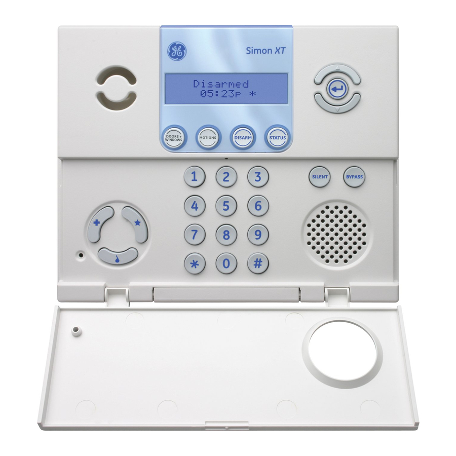
Page 40: Programming Overview
All installer options are set in the System Programming menu, except for setting the system time. Table 7 on page 31 explains the panel keys and features shown in Figure 12. Figure 12. Simon XT self-contained panel MOTIONS... -
Page 41: Entering And Exiting The System Menu
Chapter 4 Programming Table 7. Simon XT panel keys and features Control Description Piezo siren The piezo siren makes alarm beeps and status beeps. Fire and intrusion alarm beeps are always played at high volume, while the volume of status beeps (such as trouble or chime beeps, entry and exit delay beeps, or auxiliary alarm beeps) is programmable. -
Page 42: Menu Navigation
Use the scroll keys or enter a numerical value to change the option, then press the Enter key to save the change. Table 8. Simon XT menu structure System time Security... - Page 43 Chapter 4 Programming Table 8. Simon XT menu structure (continued) Sensors System options Learn sensor RF jam detect Delete sensor Demo mode Edit sensor HW1 I/O Reporting SIA limits Report options 24-hour clock format Opening report Siren options Closing report...
-
Page 44: Set Clock
Simon XT Installation Manual Set clock If the panel loses both AC and battery power, then upon restoring power the system time will reset to midnight and blink, indicating it has not been set correctly. You can set the system time to display in either 12-hour or 24-hour format. -
Page 45: System Programming
4. Press Enter. The panel is now in program mode. Note: Do not remove panel power while in program mode. Table 9. Simon XT programming codes Code Description Dealer code You can use the dealer code to program all system options, including high-security options that are not accessible with the installer code if it is different from the dealer code. -
Page 46: Security
Simon XT Installation Manual Security Table 11. Security Function Default Description Account number 00000 Lets you program up to a 10-character alphanumeric account number or delete an existing account number by pressing DISARM. You can enter numerical digits sequentially. To enter letters (A to F only), use the scroll buttons to select A to F then press Enter. -
Page 47: Phone Numbers
Chapter 4 Programming Table 11. Security (continued) Function Default Description Exit extend Determines whether the panel restarts the exit delay time if the user enters the armed premises during the initial exit delay period (on), or not (off). Turning on this feature allows users to reenter during the exit delay period, without disarming and then rearming the system. -
Page 48: Phone Options
Simon XT Installation Manual Phone options Table 13. Phone options Function Default Description Man phone test Determines whether the user can perform a manual communication test to verify communication to a central station/voice dial (on), or not (off). If you have all 4 phone # programmed it should send a test report to all 4 before showing that test is okay. -
Page 49: Sensors
Chapter 4 Programming Table 13. Phone options (continued) Function Default Description Call wait code The call waiting code is dialed by the panel before a phone number to disable call waiting. Verify that the end-user has call waiting with his phone service provider before changing this option from its default. - Page 50 Simon XT Installation Manual Learn sensor To learn a sensor: 1. Press the scroll buttons until the panel displays System programming. 2. Press Enter. The system prompts for an access code. 3. Enter the dealer or installer code and press Enter. The panel displays Access Codes.
-
Page 51: Reporting
Chapter 4 Programming Editing sensors You can use this feature to change the group or name of a sensor that is already in panel memory. The procedure is very similar to the procedure used to program sensor information after a sensor is learned in. Pressing DISARM while editing sensor text deletes all text for that sensor. - Page 52 Simon XT Installation Manual Table 16. Reporting options (continued) Function Default Description Closing reports Determines whether the panel sends closing reports to a central station whenever the system is armed (on), or not (off). User number will be reported as zone number. Keyfobs learned into zones 1 through 40 will report as the zone they are learned into.
-
Page 53: Table 17. Communication Modes
Chapter 4 Programming Table 16. Reporting options (continued) Function Default Description Swinger Determines whether the panel prevents the same sensor from activating an alarm more shutdown than once in a single arming period (on) or not (off). Note: Swinger Shutdown does not affect smoke and fire sensors. Program report Determines whether the panel sends a report to the central station anytime the programming mode is entered/exited (on) or not at all (off). -
Page 54: Timers
Simon XT Installation Manual Timers Table 18 provides timer option details. Table 18. Timers Function Default Description Latchkey time Determines whether the panel reports a latchkey alarm if the system is not disarmed at a preset time between midnight and 11:59 P.M. (on). If the latchkey feature is disabled (off), the panel will not report a latchkey alarm. -
Page 55: Touchpad Options
Chapter 4 Programming Table 18. Timers (continued) Function Default Description Fail-to-open Determines whether the panel sends a Fail to open report to a central station if the time system has not been disarmed by the programmed time (on), or not (off). System time must be set correctly for this feature to work. -
Page 56: System Options
Simon XT Installation Manual System options Table 20 provides system option details. Table 20. System options Function Default Description RF jam detect Determines whether the panel checks for and reports RF interference/jam to the central station (on) or not (off). If this option is on and the panel receives a constant 319.5 MHz signal, the panel reports the condition to the central station. -
Page 57: Siren Options
Chapter 4 Programming Siren options Table 21 provides siren option details. Table 21. Siren options Function Default Description Piezo beeps This option determines whether the panel piezo produces beeps based on system activity (on) or is silent (off). Panel voice When On, arming level changes will be spoken. -
Page 58: Piezo Beep Options
Simon XT Installation Manual Piezo beep options Table 22 provides piezo beep option details Table 22. Panel piezo beeps Activity Piezo beep response Arm doors and Exit delay—two beeps sound every five seconds and two times per second during the last ten seconds. -
Page 59: Audio Verification Options
Chapter 4 Programming Audio verification options Table 23 provides audio verification option details. Table 23. Audio verification Function Default Description Audio mode 1 = Instant. Panel stays online with central station for an instant audio session. 2 = Callback. Panel hangs up and waits for a callback from the central station operator before starting an audio session. -
Page 60: Light Control (Optional)
Simon XT Installation Manual Light control (optional) If your system uses optional X10 modules, you can program them to control lights. X10 module operation Use the following procedure to program X10 module operations into panel memory. To program the housecode: 1. - Page 61 Chapter 4 Programming 6. Press the scroll buttons until the panel displays Sensor Light. 7. Press Enter. The panel displays Sn ## <Text> X-10 unit = On/Off. 8. Press the scroll buttons until the panel displays the sensor number you want to activate. 9.
-
Page 62: System Tests
Simon XT Installation Manual Lock interval Sets the start and stop times that determine when the panel prevents the sensor-activated lights feature from turning on sensor-activated lights. Note: System time must be set correctly for this feature to work. When a time value is set (on) and the sensor-activated lights feature is on, the panel prevents sensor-activated lights from turning on between the programmed start time (this option) and the programmed stop time. -
Page 63: Resetting Memory To The Factory Defaults
Chapter 4 Programming Resetting memory to the factory defaults To reset the panel to its factory defaults, do the following: 1. Open the panel cover. 2. Unplug the transformer and disconnect the battery. 3. Press and hold the four arming/status buttons (DOORS+WINDOWS, MOTIONS, DISARM, and STATUS) on the front of the panel and the tamper switch on the inside of the panel (see Figure 5 on page 20). - Page 64 Simon XT Installation Manual...
-
Page 65: Testing
Chapter 5 Testing This section describes how to perform various test procedures. You should test the system after installing, after servicing, and after adding or removing devices from the system. In this chapter: Control panel ..........56 Sensor testing. -
Page 66: Control Panel
Simon XT Installation Manual Control panel Test the panel by pressing the buttons as described in Table 26. Table 27 provides a list of the arming levels. Note: An access code is required when arming if the Secure arming option is on. -
Page 67: Sensor Testing
Chapter 5 Testing Sensor testing Test the sensors after all programming is completed and whenever a sensor-related problem occurs. Note: While the sensor test is a valuable installation and service tool, it only tests sensor operation for the current conditions. You should perform a sensor test after any change in environment, equipment, or programming. -
Page 68: If A Sensor Fails The Sensor Test
1. Test a known good sensor at the same location. 2. If the transmission beeps remain below the minimum level, avoid mounting a sensor at that location. 3. If the known-good sensor functions, contact GE Security for repair or replacement of the problem sensor. -
Page 69: Phone Communication
Chapter 5 Testing Phone communication Perform a communication test to check the phone communication between the panel and the central station. To perform a communication test: 1. Go to the Comm Test option under the System Tests menu. 2. Press Enter. The panel confirms that a communication test has begun. When the communication test is complete, the panel will display Comm test is OK within 3 minutes. -
Page 70: Central Station Communication
Simon XT Installation Manual Central station communication After performing sensor and communication tests, check that the system is reporting alarms successfully to the central station. Table 31 provides a list of sensor/user report codes. To test communication with the central station: 1. -
Page 71: Two-Way Voice Operation
Chapter 5 Testing Two-way voice operation For the central station operator to initiate an audio session: Note: Panel voice announcements are silenced during AVM sessions. If the operator does not terminate the session correctly, panel announcements may not occur for up to 90 seconds after the operator hangs up. 1. -
Page 72: X10 Operation
Simon XT Installation Manual X10 operation The following sections describe how to test X10 lamp, siren, appliance, and universal module operation. Manual lamp module control • Control panel: Press the asterisk button (*) and the unit number of the lamp module using the numeric buttons to test individual lamp modules 1 through 8. -
Page 73: Chapter 6 Troubleshooting And Support
Chapter 6 Troubleshooting and support This chapter provides information to help you troubleshoot problems, perform simple preventive maintenance procedures, and contact technical support in case you need assistance with your GE equipment. In this chapter: Troubleshooting ..........64 Contacting technical support . -
Page 74: Troubleshooting
Simon XT Installation Manual Troubleshooting This section provides information to help you diagnose and solve various problems that may arise while configuring or using your GE product and offers technical support contacts in case you need assistance. (See Contacting technical support on page 66.) - Page 75 Chapter 6 Troubleshooting and support Sensors A sensor does not work. • Make sure the battery is good and installed correctly. • Check for interference from metal objects. Move or rotate the sensor. • Move the sensor to a new location. Door or window is closed, but the panel announces it is open.
-
Page 76: Contacting Technical Support
Simon XT Installation Manual Contacting technical support For assistance installing, operating, maintaining, and troubleshooting this product, refer to this document and any other documentation provided. If you still have questions, you may contact technical support during normal business hours (Monday through Friday, excluding holidays, between 5 a.m. and 5 p.m. Pacific Time). -
Page 77: Appendix A Specifications And Tables
Specifications and tables This appendix provides a couple lists of sensor names and a quick reference chart for operating the Simon XT system with various peripheral devices. In this appendix: Specifications..........68 Sensor names . -
Page 78: Specifications
Simon XT Installation Manual Specifications Table 35. Simon XT specifications Requirement Description Power 9 VAC, 30 VA transformer Rechargeable battery: 6.0 VDC, 1.2 Ah lead-acid. The battery will last 24 hours with no AC and specified standby load. Radio frequency 319.5 MHz... -
Page 79: Table 37. Sensor Name Segments By Index Number (In Scrolling Order)
Appendix A Specifications and tables Table 37. Sensor name segments by index number (in scrolling order) Phrase Phrase Phrase Keyfob (keychain) & Touchpad Front door Front window Back door “ Back window Garage door Garage window Master bedroom Master bedroom window Bedroom Bedroom window Guest room... -
Page 80: Table 38. Simon Xt System Quick Reference
Simon XT Installation Manual Table 38. Simon XT system quick reference Control panel Remote touchpad Keyfob Telephone Level 0: Subdisarm Enter the master code while the the system system is disarmed. Level 1: Disarm DISARM, <access_code>. Disarm the system Level 2: Arm doors DOORS+WINDOWS, <access_code>... -
Page 81: Index
Index AC power ....................27 handheld touchpads ................2, 4 access codes.................... 35 hardwired contacts.................. 22 appliance modules ................2, 28 hardwired device connections ..............20 audio verification options............... 49 housecode ....................50 autoarm....................36 indoor motion sensors ................3 back piece .................. - Page 82 Simon XT Installation Manual planning ....................6 smoke detectors ..................2, 3 police button ................... 31 system components .................. 3 power transformer wiring ............... 26 system menu ................... 31 preface ..................... ix system options ..................46 premises phone ..................25 system tests.....................
- Page 84 Simon XT Installation Manual...
Need help?
Do you have a question about the Simon XT and is the answer not in the manual?
Questions and answers