
Subscribe to Our Youtube Channel
Related Manuals for Advanced Energy AE 600


Summary of Contents for Advanced Energy AE 600
- Page 1 ® Advanced Energy AE 500 Inverter Installation and Operation User Manual 570-1001791-05A March 2012 ...
- Page 3 ® Advanced Energy AE 500 Inverter Installation and Operation User Manual 570-1001791-05A March 2012 ...
-
Page 4: Disclaimer And Limitation Of Liability
Advanced Energy Industries, Inc. shall not be liable in damages, of whatever kind, as a result of the reliance on or use of the information contained herein. - Page 5 Microsoft Corporation. CUSTOMER FEEDBACK Advanced Energy’s technical writing staff has carefully developed this manual using research-based document design principles. However, improvement is ongoing, and the writing staff welcomes and appreciates customer feedback. Please send any comments on the content, organization, or format of this user manual to: •...
- Page 6 Advanced Energy To order a manual, please contact AE Solar Energy Technical Support: • invertersupport@aei.com 570-1001791-05A...
-
Page 7: Table Of Contents
Advanced Energy® AE 500 Inverter Table of Contents Chapter 1. Safety and Product Compliance Guidelines Important Safety Instructions ................ 1-1 Save These Instructions .................. 1-1 Danger, Warning, and Caution Boxes in the Manual .......... 1-1 Safety Guidelines .................... 1-2 Rules for Safe Installation and Operation ............ 1-2 Personal Safety ..................... 1-3... - Page 8 Advanced Energy General Requirements for Planning and Installation .......... 3-1 Handling the Inverter ..................... 3-1 Handling Options .................... 3-2 Storage ........................ 3-2 Location and Clearances .................. 3-2 Location ...................... 3-2 Noise ...................... 3-2 Recommended Clearances ................ 3-2 Conduit and Conductors .................. 3-3 Environmental Requirements ................ 3-4 Grounding and Neutral Requirements .............. 3-4 PV Array Frame Grounding ................ 3-4...
- Page 9 Advanced Energy® AE 500 Inverter Chapter 5. Operation System Startup Procedure .................. 5-1 Inverter Operating States .................. 5-2 Display Screens and Operation ................ 5-4 To Operate the Display ................... 5-6 Ground Fault Interrupt Device ................ 5-6 To Respond to a Ground Fault ............... 5-7 To Shutdown the Inverter .................. 5-8 De-energize/Isolation Procedures .............. 5-9...
- Page 10 Advanced Energy Visual Inspection .................... 7-2 Maintenance Schedule .................. 7-2 Replacement Parts .................... 7-3 Checking and Replacing the Air Filters .............. 7-4 Maintaining the Air Filters ................ 7-4 Maintaining the Card Cage Air Filter .............. 7-6 Replacing the Battery on the Communications PCB .......... 7-6 Chapter 8. Troubleshooting and Solar Energy Technical Support Troubleshooting LAN Connectivity ................ 8-1...
-
Page 11: List Of Tables
Advanced Energy® AE 500 Inverter List of Tables Table 1-1. Branch breaker size recommendations .......... 1-6 Table 1-2. Acronyms and frequently used terms .......... 1-9 Table 3-1. Inverter clearances ................ 3-2 Table 3-2. Cooling and heat rejection rate requirements ........ 3-4 Table 4-1. Subcombiner wire sizing and torque values ........ 4-16 Table 4-2. - Page 12 Advanced Energy Table A-5. Cooling specifications ................. A-4 Table A-6. Environmental specifications .............. A-5 List of Tables 570-1001791-05A...
-
Page 13: List Of Figures
Advanced Energy® AE 500 Inverter List of Figures Figure 2-1. Components of the AE 500 inverter ............ 2-3 Figure 2-2. Power module assembly .............. 2-4 Figure 2-3. Control electronics compartment ............ 2-5 Figure 2-4. Data monitoring card cage assembly .......... 2-6 Figure 2-5. DC combiner sub panel .............. 2-7 Figure 2-6. - Page 14 Advanced Energy Figure 6-3. Communication interface PCB in the data monitoring section .... 6-6 Figure 6-4. Daisy chain layout for RS-485 network: option A ....... 6-7 Figure 6-5. Daisy chain layout for RS-485 network: option B ....... 6-7 Figure 6-6. Daisy chain layout for RS-485 network: option C ....... 6-7 Figure 6-7.
-
Page 15: Chapter 1. Safety And Product Compliance Guidelines
Guidelines IMPORTANT SAFETY INSTRUCTIONS To ensure safe installation and operation of the Advanced Energy AE 500 unit, read and understand this manual before attempting to install and operate this inverter. At a minimum, read and follow the safety guidelines, instructions, and practices. -
Page 16: Safety Guidelines
Advanced Energy WARNING: WARNING indicates a potentially hazardous situation that, if not avoided, could result in death or serious injury, and/or property damage. AVERTISSEMENT: AVERTISSEMENT indique une situation potentiellement dangereuse qui, si elle n’est pas évitée, pourrait provoquer la mort ou des blessures graves et/ ou des dommages matériels. -
Page 17: Personal Safety
Advanced Energy® AE 500 Inverter PERSONAL SAFETY Ensure any personnel entering a safety zone within a four foot area around any operating inverter wear appropriate Personal Protective Equipment (PPE) as mandated by national, state, and local authorities. Medical and First Aid Treatment... -
Page 18: Product Compliance
Advanced Energy Chassis ground On or off 4588 4589 Phase 4590 Electrical fuse 1025 Alternating current 1026 Direct current 4205 Positive ground Negative ground PRODUCT COMPLIANCE The following sections include information about unit compliance and certification, including the conditions of use required to be in compliance with the standards and directives. -
Page 19: Safety And Emc Directives And Standards
Advanced Energy® AE 500 Inverter Safety and EMC Directives and Standards Certain options of this unit have been tested for and comply with the following electromagnetic compatibility (EMC) and safety directives and standards and industry guidelines. ☞ Important This equipment must be installed and used in accordance with the Conditions of Use described in this manual. -
Page 20: Wiring Requirements
Advanced Energy AC/DC DISCONNECT DEVICE AND OTHER REQUIREMENTS If the optional inverter integrated AC disconnect and inverter integrated DC subcombiner breakers were not selected, then isolated disconnect devices must be provided for both the PV array DC connection and for the AC utility grid connection when installing an AE inverter. - Page 21 Advanced Energy® AE 500 Inverter DANGER: Ne pas brancher les conducteurs négatifs ou positifs du PV aux barres omnibus mises à la terre fournies. Le panneau photovoltaïque est mis à la terre au moyen du GFDI. La connexion des conducteurs positifs ou négatifs du panneau photovoltaïque à...
-
Page 22: Fire Prevention
Advanced Energy Ensure phase cables run together through conduit and gland plates, which allows any inductive currents produced to be cancelled out. Use proper torque values for terminal lug mounting hardware. A copper clad earth grounding electrode must be installed within three feet (one meter) of the unit. -
Page 23: Acronyms And Frequently Used Terms
Advanced Energy® AE 500 Inverter ACRONYMS AND FREQUENTLY USED TERMS Table 1‑2. Acronyms and frequently used terms Term Description Action delay A predefined delay before a set point change. Analog to digital conversion ANSI American National Standards Institute BEMS Building energy management system... - Page 24 Advanced Energy Table 1‑2. Acronyms and frequently used terms (Continued) Term Description Network time protocol OEM mode Original equipment manufacturer mode Printed circuit board Power factor Phase lock loop Personal protective equipment Photovoltaic PV monitoring PVM Sync Software application used to query inverters.
-
Page 25: Chapter 2. Product Overview
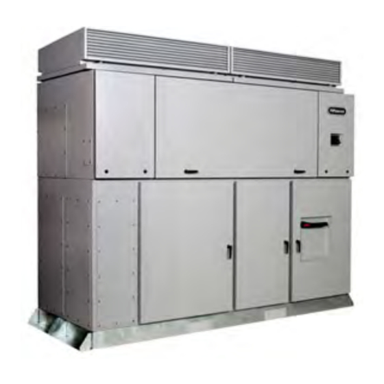
Chapter Product Overview GENERAL DESCRIPTION The Advanced Energy inverter is designed to act exclusively as a grid-tied inverter for photovoltaic (PV) systems. The inverter converts direct current (DC) electricity generated by the photovoltaic arrays into usable alternating current (AC) electricity. -
Page 26: Product Features
Advanced Energy PRODUCT FEATURES The design of the AE 500 inverter includes the following standard features. • Equipped with redundant cooling system with variable speed fans and fault detection. The built-in backup capabilities enables the inverter to deliver full power at the maximum rated temperature even if one of the fans should fail. -
Page 27: Major Components And Functional Parts
Advanced Energy® AE 500 Inverter MAJOR COMPONENTS AND FUNCTIONAL PARTS Data monitoring Air intake hood Power module assembly Control electronics Display DC sub panel AC sub panel DC combiner sub panel Ripple filter DC landing Figure 2‑1. Components of the AE 500 inverter The modular design of the inverter makes them easy to access and service. -
Page 28: Power Module Assembly
Advanced Energy Power Module Assembly The inverter uses insulated gate bipolar transistors (IGBTs) for converting DC power into three-phase AC power. The inverter is protected by over-current, over-voltage, and over-temperature detection controls. If a protection system is activated, the power module will cease power conversion and send an interrupt signal to the digital signal processor (DSP). -
Page 29: Data Monitoring Card Cage
Advanced Energy® AE 500 Inverter Control electronics compartment GFDI Control electronics backplane Control electronics card cage Figure 2‑3. Control electronics compartment WARNING: Risk of electrical shock. The GFDI functions using a fuse to connect or bond the solar array negative (or the solar array positive, if using a positively grounded panel array) to earth ground. -
Page 30: Communications Interface Pcb
Advanced Energy The data monitoring card cage houses the following: • Communications PCB: Provides serial, internet, and Modbus communications. • Power distribution PCB: Distributes the required logic level voltages for use throughout the inverter. • User interface PCB: Provides accessible DIP switches for Modbus addressing and termination. -
Page 31: Active Cooling System
Advanced Energy® AE 500 Inverter Active Cooling System The inverters come with fans which activate as needed to keep the internal components within preset temperature limits. These fans are located on each side of the inverter. DC Combiner Sub Panel The DC combiner sub panel compartment is where the inverter connections to the PV source circuits are completed, including the positive, negative, and ground bus bars. -
Page 32: Ac Sub Panel
Advanced Energy DC line filter DC surge protection DC contactor DC current shunt Figure 2‑6. DC sub panel AC Sub Panel The AC landing, AC surge protection, soft start contactor and ground reside in the AC sub panel. The sub panel also includes the optional AC disconnect and revenue meter. -
Page 33: Housekeeping Transformer
Advanced Energy® AE 500 Inverter Housekeeping Transformer The housekeeping transformer, located in the upper right in the control electronics compartment, is a voltage conversion device that transforms 480 VAC to 120/160 VAC for use within the inverter. Magnetics Compartment The magnetics compartment contains the isolation transformer and the inductors. - Page 34 Advanced Energy 2‑10 Product Overview 570-1001791-05A...
-
Page 35: Chapter 3. Planning
Advanced Energy® AE 500 Inverter Chapter Planning GENERAL REQUIREMENTS FOR PLANNING AND INSTALLATION Planning for an installation of an AE inverter should only be performed by qualified engineers with a thorough understanding of the processes involved for a successful installation. Licensed and trained installers must comply with all local and national code requirements for the installation of electrical power systems with AC and DC voltages to 600 V. -
Page 36: Handling Options
Advanced Energy ☞ Important Do not lift the inverter from the upper bolt points. Handling Options The AE 500 inverter may also be moved using lifting bars inserted through the front to back fork slot openings. ☞ Important Use only the front and rear fork slots. Do not use side slots to move the inverter. -
Page 37: Conduit And Conductors
Advanced Energy® AE 500 Inverter Table 3‑1. Inverter clearances (Continued) Location Distance Description Rear 24″ The rear clearance is required behind the inverter to allow room for full opening of the air intake hoods. Sides 36″ The minimum side clearances are 36″ in order open the side panels and work on internal components when neessary. -
Page 38: Environmental Requirements
Advanced Energy External cable interfaces are through bottom or side gland plates. The gland plates must be in place for operation of the inverter. Gland plate locations are included on the mechanical drawings in the appendix. ENVIRONMENTAL REQUIREMENTS The unit may be installed either indoors or outdoors. If the installation of the inverter is outdoors, all interconnect conduit and fittings must be rated NEMA 4 (same as the inverter rating) as required by the NEC. -
Page 39: System Neutral
à la terre correspond à votre plan de mise à la terre d’installation. Si on a besoin de reconfigurer la mise à la terre, contacter Advanced Energy pour de l’aide. NE PAS mettre à la terre le fil CC au moment de l’installation. Cela déjouerait le circuit GFDI. -
Page 40: Utility Grid Interconnection
Advanced Energy AVERTISSEMENT: La sortie et le neutre CA ne doivent pas être branchés à la masse à l’intérieur du dispositif. UTILITY GRID INTERCONNECTION Utility Connection Requirements Review all applicable national or local codes for specific requirements for the size of the electrical service and the amount of current that is allowed to be fed into the panel by the inverter. -
Page 41: Calculating Dc Input Voltage
To Calculate Maximum Open Circuit Voltage • Calculate the maximum open circuit (no load) voltage for each series module connection. Refer to the Advanced Energy Solar Energy web site and select the String Calculator to calculate the input from the PV array. -
Page 42: Breaker Protection For Dc Input
Advanced Energy 8 circuit option 16 circuit option 20 circuit option 8 circuit with 16 circuit with monitoring option monitoring option Figure 3‑2. DC subcombiner options Breaker Protection for DC Input The installer is responsible for providing proper over current protection for the DC input circuit if the subcombiner circuit breaker option is not included. -
Page 43: Chapter 4. Installing
Advanced Energy® AE 500 Inverter Chapter Installing HANDLING AND UNPACKING This section describes the required safe handling and unpacking procedures for the AE inverter. Always follow the recommendations in this section to prevent accidental damage or injury. WARNING: Heavy equipment. AE 500 units weigh up to 4,140 kgs (9,100 lbs) with pallet and packaging. -
Page 44: Installing The Air Intake Hoods
Advanced Energy • Lifting device such as a forklift or pallet jack • Utility knife The inverter can be moved using a forklift or pallet jack that is rated to handle a minimum of 4,140 kgs (9,100 lbs). TO UNLOAD AND UNPACK THE INVERTER 1. -
Page 45: Figure 4-1. Stacked Air Intake Hoods
Advanced Energy® AE 500 Inverter Hood lifting point Lifting point with eyebolt Figure 4‑1. Stacked air intake hoods 2. Insert eyebolts through the lifting point holes on each end of one air intake hood. Secure the eyebolts. 3. Connect a lifting strap securely to each eyebolt. -
Page 46: Figure 4-2. Placing The Air Intake Hood On The Inverter
Advanced Energy Rear hinges Figure 4‑2. Placing the air intake hood on the inverter 5. Set the two back hinges on the rear edge of the air intake hood, on the rear top edge of the inverter cabinet while aligning the hinge barrels. -
Page 47: Pre-Installation Inspection
Advanced Energy® AE 500 Inverter Gas spring Ball Figure 4‑4. Attaching the hood's gas springs to the inverter 9. Remove the lifting strap and the eyebolts from the installed air intake hood. 10. Close the air intake hood. 11. Using a slotted screw driver, engage all three latches, by rotating clockwise, to secure the front edge of the air intake hoods. -
Page 48: Step 1: External Inspection
Advanced Energy Step 1: External Inspection 1. Inspect the shipping materials and the inverter for any cosmetic or structural damage. Specifically look for any structural damage or crushing of the base or doors. 2. Confirm all doors open freely and easily. -
Page 49: Step 3: Ac And Dc Sub Panel Compartments
Advanced Energy® AE 500 Inverter 3. Check the screens at the bottom of the compartment for damage or debris. 4. Replace the cover plates. Make sure the gaskets are not damaged during replacement of the plates. Do not overtighten the screws. -
Page 50: Step 4: Power Module Compartment
Advanced Energy Cable screw terminals Figure 4‑7. Pull test of cable screw terminal connection 4. Inspect the screens at the bottom of the compartment for damage or debris. DC bottom entry gland plate 4686 Figure 4‑8. Screen inspection If any loose wires are found during the inspections, and the correct location of the connection is unknown, contact AE Solar Energy Technical Support. -
Page 51: Step 5: Upper Active Cooling Compartment
Advanced Energy® AE 500 Inverter 4678 Bus bar connections Figure 4‑9. Check the bus bar connections Step 5: Upper Active Cooling Compartment 1. Ensure the fans spin freely. Screws Check connections Check connections Figure 4‑10. Fan inspection 2. Ensure all air filters are fully seated. -
Page 52: Lifting And Mounting The Inverter
Advanced Energy Air filters 4680 Figure 4‑11. Air filter check This completes the pre-installation inspections. LIFTING AND MOUNTING THE INVERTER The inverter base is designed to allow a properly rated forklift to lift it from the front or back using the fork slots. - Page 53 Advanced Energy® AE 500 Inverter ◦ Using lifting beams, spreader bars, or similar equipment rated for the weight of the inverter To Lift and Mount the Unit WARNING: Do not attempt to lift the full weight of the unit from the left or right sides only.
-
Page 54: Conduit Entry Points
Advanced Energy Alternate methods of lifting and positioning the inverter may be used. Proper methods may include the use of a crane with a strap rated for the weight of the inverter; however, care MUST be taken to protect the inverter from compressive stresses or forces which may dent or deform the cabinet or cause damage to the inverter. -
Page 55: Figure 4-12. Dc Bottom Entry Gland Plates
Advanced Energy® AE 500 Inverter The bottom chases are located beneath the bottom DC and AC gland plates. If the bottom side chase is used, the bottom DC and AC gland plates are not needed and can be removed from the cabinet. The gland plates should not be left loose in the compartment. -
Page 56: Figure 4-13. Dc Side Entry Gland Plates
Advanced Energy Cover for fan compartment Service access only Side entry gland plates Figure 4‑13. DC side entry gland plates 2. Remove the gland plate while taking care not to damage the weatherproof gasket material on the back side of the plate. -
Page 57: Electrical Connections
Advanced Energy® AE 500 Inverter 5. Replace the gland plate taking care to evenly seat the gasket material against the cabinet. 6. Tighten until the gland plate is snug. Do not overtighten. ELECTRICAL CONNECTIONS DANGER: Electrical connections must comply with national and local standards. -
Page 58: Ac Wiring
Advanced Energy Table 4‑1. Subcombiner wire sizing and torque values Maximum Wire Size Required Terminal Breaker Torque Temp. Frame Rating Maximum Amperage 8 x 400 Direct to bus bar. No wire size limit. 40 ft-lbs 90°C Attach lug to bus bar with grade 8, 3/8″... -
Page 59: Table 4-2. Branch Breaker Size Recommendations
Advanced Energy® AE 500 Inverter CAUTION: The input and output circuits are isolated from the enclosure. System grounding, when required by national and local electrical code, is the responsibility of the installer. ATTENTION: Les circuits d’entrée et de sortie sont isolés de l’enceinte. La mise à la terre du système, lorsqu’elle est exigée par le code d’électricité... -
Page 60: Connecting To The Electrical Grid
Advanced Energy When an inverter is installed on an electrical panel the AC operating voltage range of the inverter should be considered. Voltages outside this range will cause the inverter to fault. See the specifications section of this manual for AC operating voltage ranges. - Page 61 Advanced Energy® AE 500 Inverter WARNING: Do not connect a neutral wire to the WYE point of the isolation transformer. Doing so will cause the inverter to malfunction and will void the warranty. AVERTISSEMENT: Ne branchez pas de câble neutre au point WYE du transformateur d’isolation.
-
Page 62: Figure 4-15. Ac Connections
Advanced Energy b. Phase A, B, and C to the AC landings inside the inverter. ☞ Important The inverter auto phases and will auto detect phase rotation. Optional revenue meter AC surge Soft start contactor Optional AC disconnect AC landing Ground Figure 4‑15. AC connections... -
Page 63: Dc Wiring
Advanced Energy® AE 500 Inverter Use grade 8, 3/8″ hardware to secure the lugs of the outgoing AC cables to the bus bars. 6. Ensure all connections are wired correctly and properly torqued. Tighten the AC terminal screws to 40 ft-lbs. -
Page 64: Connecting To The Pv Arrays
Advanced Energy Ground bus bar DC+ bus bar DC- bus bar Figure 4‑17. DC connections CONNECTING TO THE PV ARRAYS DANGER: Risk of electrical shock. When exposed to light, PV arrays create electrical energy that could cause a hazardous condition. ... -
Page 65: Figure 4-18. Dc Subcombiner Configurations
Advanced Energy® AE 500 Inverter To Connect the DC Wiring 8 circuit option 16 circuit option 20 circuit option 8 circuit with 16 circuit with monitoring option monitoring option Figure 4‑18. DC subcombiner configurations 1. Disconnect power to the DC wiring by disconnecting the PV array outside the inverter before starting the DC wiring. -
Page 66: Figure 4-19. Dc Dead Front
Advanced Energy Breakers DC+ bus bar Dead front Figure 4‑19. DC dead front 5. Connect the PV frame ground wire(s) to the ground lug on the point marked in the lower left side of the cabinet. 6. Connect positive DC cables(s) to the terminals located on the positive bus bar or the breaker by inserting the cable directly into the breaker frame terminal depending on the configuration. -
Page 67: Using The Integrated Remote Disable Input
Advanced Energy® AE 500 Inverter Bus bar Crimp connector Washer, 3/8 high strength Screw, hex cap, 3/8 - 16 x 1, Grade 8 Washer, Belleville, 3/8, 6500 lb flat load 4618 Nut, hex, 3/8 - 16, Grade 8 Figure 4‑20. DC inverter connections 8. -
Page 68: Making The Remote Disable Connection
Advanced Energy ☞ Important Termination switches are located on the communications PCB terminal to allow normal operation. Do not move the switches unless you intend to use this feature. ☞ Important Closing the remote disable contact with the inverter ON/OFF switch in the ON position will re-start the inverter. -
Page 69: Figure 4-21. Remote Disable Wiring Diagram
Advanced Energy® AE 500 Inverter Closed Remote Contacts = Inverter Enabled Inverter Remote Remote Contacts Disable Terminals Control Wire Open Remote Contacts = Inverter Disabled Inverter Remote Remote Contacts Disable Terminals Control Wire Figure 4‑21. Remote disable wiring diagram To Make the Remote Disable Connection DANGER: Risk of electrical shock. -
Page 70: 24 V Power Supply
Advanced Energy The data monitoring gland plate is a small, flat piece of metal covering the side entry port to the inverter’s data monitoring compartment. 3. Drill or punch a hole in the desired location to allow access for the remote disable control wires. -
Page 71: Wiring The 24 V Power Supply
Advanced Energy® AE 500 Inverter 24 V power supply is not installed, an additional power supply will need to be provided by the installer. The additional power supply will need to be installed external to the inverter. The integrated 24 V power supply meets the following specifications: •... -
Page 72: Figure 4-24. 24 V Wiring Example
Advanced Energy • Small flat head screwdriver • Voltage meter To Make the 24 V Terminal Connections The following information describes how to make the 24 V power supply connection on the AE 500 inverter. The 24 V terminal block contains three sets of terminals to run control power wiring to the field. -
Page 73: Chapter 5. Operation
Advanced Energy® AE 500 Inverter Chapter Operation SYSTEM STARTUP PROCEDURE WARNING: Before turning on the inverter, ensure that the front panels are closed properly. AVERTISSEMENT: Assurez-vous de la bonne fermeture des panneaux antérieurs avant de mettre l’onduleur en route. -
Page 74: Inverter Operating States
Advanced Energy 10. Turn the ON/OFF switch to the ON position. After five minutes, the inverter starts to produce power into the AC grid if all necessary operating conditions are met. Display Disconnect in power on position 4685 Figure 5‑1. Inverter with AC disconnect power ON If the unit fails to power on, use the troubleshooting information provided in this manual. -
Page 75: Figure 5-2. Inverter State Diagram
Advanced Energy® AE 500 Inverter Initialize Disabled Sleep Startup Delay Fault Cool Down Precharge Precharge Power Track (auto Idle mode) Figure 5‑2. Inverter state diagram • Initialize: The inverter enters this state after a power cycle. Variables and devices are initialized and I/O ports set. When initialization is complete, the inverter enters the sleep state. -
Page 76: Display Screens And Operation
Advanced Energy • Sleep: In this state, the inverter is enabled but the DC voltage is below the minimum operating window. When the PV input voltage rises above the starting voltage, the inverter switches to the startup delay state. • Startup Delay: In this state, the inverter delays a specified time and then enters the DC precharge state. -
Page 77: Figure 5-3. Initialize State Screen
Advanced Energy® AE 500 Inverter • Initialize: The initialize state is displayed on the screen when the inverter is first turned on. • Energy tracking: These are the normal power production states of idle, run, and AC and DC precharge. Following the startup delay, the inverter goes to energy tracking which starts with the DC and AC precharge and then goes to idle and run. -
Page 78: To Operate The Display
Advanced Energy 4654 Figure 5‑6. Warning state screen 4651 Figure 5‑7. Disabled state screen To Operate the Display The inverter display scrolls through a series of display screens based on the current state of the inverter. To operate the display: • Press the Pause/Scroll button to pause the display on a specific screen •... -
Page 79: To Respond To A Ground Fault
Advanced Energy® AE 500 Inverter WARNING: For the GFDI circuit to function as designed, the solar array safety ground must not be connected to the PV array positive or negative leads. Bonding the safety ground to the grounded leg of the array anywhere but through the inverter will cause the GFDI circuit to be bypassed. -
Page 80: To Shutdown The Inverter
Advanced Energy TO SHUTDOWN THE INVERTER DANGER: This unit contains energy storage devices that take up to 5 minutes to discharge. Verify the high energy capacitors are completely discharged before working on this unit. DANGER: Cette unité contient des dispositifs de stockage d’énergie qui prennent jusqu’à... -
Page 81: De-Energize/Isolation Procedures
Advanced Energy® AE 500 Inverter De-energize/Isolation Procedures DANGER: Risk of electrical shock. When exposed to light, PV arrays create electrical energy that could cause a hazardous condition. DANGER: Risque d’électrocution. L’autorisation officielle de votre compagnie locale d’électricité est requise avant de brancher l’onduleur sur le réseau public. -
Page 82: Inverter Enable/Disable Controls
Advanced Energy Inverter Enable/Disable Controls The table below shows the interaction of the inverter on/off controls. Cells containing an x can be in either state. Table 5‑1. Inverter enable/disable Inverter Enable/ Inverter Remote Enable/ Modbus Inverter Status Disable Switch Disconnect... -
Page 83: Chapter 6. Data Monitoring And Controls
Advanced Energy® AE 500 Inverter Chapter Data Monitoring and Controls NETWORKING AND PERFORMANCE MONITORING The inverter has an integrated data monitoring module located in the dedicated data monitoring compartment. The data monitoring module enables access to the inverter performance data using the following methods: •... -
Page 84: Connecting The Ethernet Cable
Advanced Energy with the AE data center using https (port 443). Communications is one way – the inverter only communicates externally to the AE data center. Typically the inverter posts approximately 50 kB of data to the data center every 15 minutes. The inverter may post data more frequently for a short period of time if there is an inverter fault. -
Page 85: To Establish An Internet Connection With The Inverter
Advanced Energy® AE 500 Inverter 2. Plug the Ethernet cable into the Ethernet port on the communication interface PCB located in the data monitoring section of the inverter. Refer to the following figure for the port location. Ethernet port Figure 6‑2. Communication interface PCB Ethernet port location Related Links •... -
Page 86: To Verify Data Monitoring Connectivity
Advanced Energy monitoring tools. Contact AE Solar Energy Technical Support if additional information is needed on how to use the online tool. To Verify Data Monitoring Connectivity Verify connectivity using the following information: 1. Check the status light located on the front of the communication PCB in the card cage on the right side of the upper compartment in the data monitoring section. -
Page 87: Modbus Tcp Installation
Advanced Energy® AE 500 Inverter ◦ Consult the facility IT administrator for network device installation support and coordination ◦ Install the Modbus network communications cabling • Modbus network configuration: This step can be done onsite or remotely and should be completed by the Modbus network programmer ◦... -
Page 88: Modbus Tcp Network Configuration
Advanced Energy Communication interface PCB 4687 Figure 6‑3. Communication interface PCB in the data monitoring section Modbus TCP Network Configuration TO ASSIGN THE IP ADDRESS AND PORT ID 1. Contact the facility’s IT Network Administrator (or person with similar responsibilities) to assign an IP address to each inverter. Advanced users can assign a static IP address. -
Page 89: Network Layout
Advanced Energy® AE 500 Inverter ☞ Important The contractor responsible for network programming will need to provide the slave addresses prior to setting the Modbus address for each slave inverter. The final part of the RS-485 installation process is the Modbus network configuration. -
Page 90: Installing The Modbus Rs-485 Cable
Advanced Energy Installing the Modbus RS-485 Cable MODBUS RS-485 WIRING REQUIREMENTS The Modbus RTU connections are made using shielded, insulated, 18-24 gauge twisted-pair communication cable that has a characteristic impedance of 120 ohms. If the RS-485 network will not pass through any high voltage (> 300 V) areas, then 300 V rated cable may be used in the low voltage data monitoring compartment of the inverter. -
Page 91: Setting The Dip Switches
Advanced Energy® AE 500 Inverter 7. Connect each Modbus cable to a slave port terminal block on the communications interface PCB. Connect the plus (+) cables to plus (+) connections and the minus (-) cables to minus (-) connections so they correspond throughout the network. -
Page 92: To Terminate The Inverter Network
Advanced Energy Termination DIP switches Figure 6‑8. Termination switches on the user interface PCB The performance of your Modbus network may require each end of the network to be terminated using 120 Ω termination resistors. When the network is long, relative to the RS-485 bit rate in use, bus terminations must be installed. -
Page 93: To Set The Center Inverters For The Network
Advanced Energy® AE 500 Inverter TO SET THE CENTER INVERTERS FOR THE NETWORK On the front of the user interface PCB, using the Modbus Termination switches: 1. Place the Low switch in the OFF position. 2. Place the Line switch in the OFF position. -
Page 94: Figure 6-9. Setting The Modbus Address
Advanced Energy Modbus DIP switches Figure 6‑9. Setting the Modbus address TO SET THE MODBUS ADDRESS 1. Determine each slave address. 2. Set the address on each slave device. The slave address is set using the Modbus Address switches on the front of the user interface PCB. -
Page 95: Table 6-2. Inverter Address Table
Advanced Energy® AE 500 Inverter Addr 1 Addr 1 4670 Figure 6‑10. Example: Unit address switch set to address 25 If you need more device addresses than the 80 provided in the following table, refer to a complete digital to binary conversion table. - Page 96 Advanced Energy Table 6‑2. Inverter address table (Continued) Switch Number Unit Address (decima Switch Address 6‑14 Data Monitoring and Controls 570-1001791-05A...
- Page 97 Advanced Energy® AE 500 Inverter Table 6‑2. Inverter address table (Continued) Switch Number Unit Address (decima Switch Address 570-1001791-05A Data Monitoring and Controls 6‑15...
-
Page 98: Modbus Commands
Advanced Energy MODBUS COMMANDS All AE commercial inverters support basic Modbus commands. The commands in the following table are used to read and write (set) inverter operating parameters or obtain the unit's identifying information. Table 6‑3. Modbus commands Command Name... -
Page 99: Table 6-5. Response Format For Read Holding Register Command
Advanced Energy® AE 500 Inverter Table 6‑4. Format for Read Holding Register command (Continued) Command Information Command Layout CRC MSB Table 6‑5. Response format for Read Holding Register command Response Information Response Layout Modbus address Command number Number of bytes of data... -
Page 100: Return Slave Id
Advanced Energy Table 6‑7. Response format for Write Single Register command (Continued) Response Information Response Layout Number of bytes of data First register MSB First register LSB Data MSB Data LSB CRC LSB CRC MSB Return Slave ID The Return Slave ID command is used to read a text string containing the ID number of the inverter. -
Page 101: Modbus Data Types
Advanced Energy® AE 500 Inverter Table 6‑9. Format for Return Slave ID command (Continued) Response Information Response Layout CRC LSB CRC MSB MODBUS DATA TYPES Modbus data types used with the AE 500 unit are shown in the following table. Table 6‑10. Data types... -
Page 102: Table 6-11. Modbus Fixed Information Registers
Advanced Energy Table 6‑11. Modbus fixed information registers Description Start No. of Modbus Data Notes Register Register Registers Address Type Modbus base address = 0 Inverter ID 40001 ASCII The ID number number is a 16-character number that is unique for each inverter. -
Page 103: Table 6-12. Inverter Model Number
Advanced Energy® AE 500 Inverter Table 6‑12. Inverter model number Inverter Model Modbus Model Number PVP30kW 0272, 0273, 0274, 0288, 0289, 0290 PVP35kW 0300, 0301, 0302, 0303 PVP50kW 0304, 0305, 0306, 0307 PVP75kW 0276, 0277, 0278, 0279 PVP100kW 0280, 0281, 0282, 0283... -
Page 104: Modbus Data Registers
Advanced Energy Table 6‑13. Bit mapping for inverter configuration register (Continued) Inverter Configuration Bit Mapping Instructions Positive ground 0x0400 This bit is: • Set if the inverter is configured for positive ground • Clear if the inverter is configured for negative... -
Page 105: Modbus Status And Fault Code Registers
Advanced Energy® AE 500 Inverter Table 6‑14. Modbus data registers (Continued) Description Start No. of Modbus Data Notes Register Register Registers Address Type Modbus base address = 1000 Total kWh 1020 1021 41021 UINT32 0 to 4.29e9 delivered PV input 1022... -
Page 106: Table 6-16. Modbus Inverter Operating Status Register Values
Advanced Energy Table 6‑15. Modbus status and fault code registers (Continued) Description Start No. of Modbus Data Notes Register Register Registers Address Type Modbus base address = 2000 Voltage fault 2103 2103 42104 UINT16 See the fault codes descriptions in the inverter troubleshooting information. -
Page 107: Table 6-17. Pvm Status Register Status Code Values
Advanced Energy® AE 500 Inverter Table 6‑16. Modbus inverter operating status register values (Continued) Description Hex Value Decimal Value Modbus register number = 42101 DC precharge state Idle state Power track state Reserved Reserved Reserved Fault state Initialization state Disabled state... -
Page 108: Modbus Command Registers
Advanced Energy Table 6‑17. PVM status register status code values (Continued) Description Hex Value Decimal Value Notes Modbus register number = 42005 Wrong Incompatible or communications incorrect revision of firmware communications firmware. Modbus address error Failed reading the Modbus address switches. - Page 109 Advanced Energy® AE 500 Inverter Table 6‑18. Modbus command registers (Continued) Description Start No. of Modbus Data Notes Register Register Registers Address Type Modbus base address = 3000 Enable 3002 3002 43003 UINT16 Write values: inverter • 0xDD to disable • 0xEE to...
- Page 110 Advanced Energy 6‑28 Data Monitoring and Controls 570-1001791-05A...
-
Page 111: Chapter 7. Maintenance
Advanced Energy® AE 500 Inverter Chapter Maintenance WARNING: These servicing instructions are for use by qualified personnel only. To reduce the risk of electric shock, do not perform any servicing other than that specified in the operating instructions. AVERTISSEMENT: Ces instructions d’entretien sont destinées uniquement à... -
Page 112: Advanced Energy
Advanced Energy VISUAL INSPECTION DANGER: Risk of electrical shock. High voltages are present in the inverter cabinet. Both AC and DC disconnects must be in the OFF position when working on the unit. Wait five minutes to discharge high voltage before opening the front panels of the inverter. -
Page 113: Replacement Parts
Advanced Energy® AE 500 Inverter Table 7‑1. Maintenance checklist Item # Check or Procedure Annual Maintenance General inspection and cleaning Record general site conditions. Record inverter performance data from inverter display. Record environmental conditions. Remove dirt and debris from underneath the inverter. -
Page 114: Checking And Replacing The Air Filters
Advanced Energy Table 7‑2. Inverter replacement parts Part Replacement Schedule Door seal gaskets 5 years Battery (CR1216) When a Real Time Clock error occurs in Modbus PVM status register 42005. Air filters As needed Card cage filter As needed CHECKING AND REPLACING THE AIR... -
Page 115: Figure 7-1. Air Intake Hoods
Advanced Energy® AE 500 Inverter Air filters 4680 Figure 7‑1. Air intake hoods 3. Remove the filters using a 5/32″ Allen wrench. 4. Clean the filters by vacuuming or blowing out using an air hose with a diffuser. If there is significant accumulation of dust or particulate matter within the filter fabric, areas of visible blockage to air flow, or physical damage, replace the affected filters. -
Page 116: Maintaining The Card Cage Air Filter
Advanced Energy Maintaining the Card Cage Air Filter TO MAINTAIN THE CARD CAGE FILTER The card cage features a secondary air filter to ensure long PCB life. The card cage air filter is located under the intake air shroud above the card cage located in the upper right compartment. - Page 117 Advanced Energy® AE 500 Inverter To Replace the Battery Use the following instructions to access the battery. 1. Shutdown the inverter and wait five minutes before starting. 2. Remove the communications PCB from the card cage in the data monitoring compartment.
- Page 118 Advanced Energy 7‑8 Maintenance 570-1001791-05A...
-
Page 119: Chapter 8. Troubleshooting And Solar Energy Technical Support
Advanced Energy® AE 500 Inverter Chapter Troubleshooting and Solar Energy Technical Support WARNING: Maintenance personnel must receive proper training before installing, troubleshooting, or maintaining high-energy electrical equipment. Potentially lethal voltages could cause death, serious personal injury, or damage to the equipment. -
Page 120: To Test The Lan Cable
Advanced Energy To Test the LAN Cable AE recommends using pre-made cables whenever possible. If a cable must be hand- crimped, we recommend: • Test the cable with a cable tester such as a Fluke LinkRunner™ Pro Network Multimeter (LPRO1000). -
Page 121: Troubleshooting Warnings
Advanced Energy® AE 500 Inverter Before performing advanced troubleshooting, the inverter must be de-energized. Prior to conducting the following troubleshooting steps, perform a visual inspection to check for the following: • Loose or disconnected wires • Fuses • Other connections •... -
Page 122: Troubleshooting Inverter Faults
Advanced Energy Table 8‑1. Inverter system warnings Hexadecimal Display String Description Action Value 0001 FAN 1 WARNING Fan 1 warning 0002 FAN 2 WARNING Fan 2 warning 0008 MAG HITEMP Magnetics high WARNING temperature warning 0010 HI TEMP PWR Power foldback warning... -
Page 123: Ac Under Voltage Fault
Advanced Energy® AE 500 Inverter In the following example, a system fault, SYS returned a code, indicating too many fault restarts occurred. The 0000 indicates no fault occurred in the other fault groups. Fault Codes Fault Advanced Energy SYS 0020... -
Page 124: To Resolve A Ground Fault
Advanced Energy AVERTISSEMENT: Pour que le circuit GFDI fonctionne normalement, la prise de terre de sécurité du système PV ne doit pas être branché aux câbles positifs ou négatifs des piles PV. Brancher la prise de terre de sécurité au pied des piles ou à... - Page 125 Advanced Energy® AE 500 Inverter DANGER: Cette unité contient des dispositifs de stockage d’énergie qui prennent jusqu’à 5 minutes pour se décharger. Vérifier que les condensateurs à haute énergie sont complètement déchargés avant de travailler sur l’unité. DANGER: Verify that no shock hazard exists between both fuse terminals and earth ground before removing the fuse.
-
Page 126: Inverter Fault Codes
Advanced Energy INVERTER FAULT CODES The inverter display screen provides fault information. In addition, the inverter firmware utilizes a Modbus variable to indicate a fault condition. Each bit in this fault variable represents a fault type, the same fault type displayed on the screen. The... -
Page 127: Table 8-3. Drive (Drv) Faults
Advanced Energy® AE 500 Inverter Table 8‑3. Drive (DRV) faults Display Display Screen Text Description Action Screen Hex Value 0001 DRIVE A LOW Drive protection fault, phase A low 0002 DRIVE A HIGH Drive protection fault, phase B high 0004... -
Page 128: Table 8-4. Voltage (Vlt) Faults
Advanced Energy Table 8‑4. Voltage (VLT) faults Display Display Screen Text Description Action Screen Hex Value 0001 VAC OVER PEAK A Peak AC voltage high, phase A 0002 VAC OVER PEAK B Peak AC voltage high, phase A 0004 VAC OVER PEAK C... -
Page 129: Table 8-5. Grid (Grd) Faults
Advanced Energy® AE 500 Inverter Table 8‑5. Grid (GRD) faults Display Display Screen Text Description Action Screen Hex Value 0001 AC FAST UNDERVOLT Fast AC voltage low, phase A 0002 AC FAST UNDERVOLT Fast AC voltage low, phase B 0004... -
Page 130: Table 8-6. Temperature (Tmp) Faults
Advanced Energy Table 8‑6. Temperature (TMP) faults Display Display Screen Text Description Action Screen Hex Value 0001 HEATSINK TEMP A1 Module heat-sink A1 temperature high 0002 HEATSINK TEMP A2 Module heat-sink A2 temperature high 0004 HEATSINK TEMP B1 Module heat-sink B1... -
Page 131: Pcb Status Leds
Advanced Energy® AE 500 Inverter Table 8‑7. System (SYS) faults (Continued) Display Display Screen Text Description Action Screen Hex Value 0008 WD TIMER Watchdog fault 0010 CPU LOAD CPU load fault 0020 RESTART LIMIT Too many fault restarts Contact AE Solar... -
Page 132: Communication Pcb Status Leds
Advanced Energy Table 8‑8. Controller PCB LEDs (Continued) Flash LED Sequence / Unit Action Color Code Status Solid The inverter is in a faulted • Check the fault code on the display condition. screen • Clear the fault condition • Inverter will auto reset Flashing A latching fault has occurred. -
Page 133: Table 8-9. Link Led
Advanced Energy® AE 500 Inverter The other set of LEDs are on the communication interface PCB located in the data monitoring section in the front upper left of the inverter. These four LEDs are surface mount LEDs located near the Ethernet and Modbus connector as shown in the following figure. -
Page 134: Table 8-11. Status Led
Advanced Energy Table 8‑11. Status LED Flash Code Unit Status / Description Action Color Green Serial communication is established. None Inverter communications are operating normally. • On solid for a few seconds • Followed by quick flashes for several seconds while the communications... -
Page 135: Table 8-12. Modbus Led
Advanced Energy® AE 500 Inverter Table 8‑11. Status LED (Continued) Flash Code Unit Status / Description Action Color Short-Short- Network connection fault. The inverter • Verify network Long cannot post data to the AE database server. cable is The status LED may indicate normal connected. -
Page 136: Ae Solar Energy Technical Support
Support to request an RMA and obtain the correct shipping address. If you would prefer to contact a local or regional sales or service office, visit the Advanced Energy web site for current contact information (click on Sales and Support): • http://www.advanced-energy.com 8‑18... -
Page 137: Appendix A. Specifications
Advanced Energy® AE 500 Inverter Appendix Specifications PHYSICAL SPECIFICATIONS Table 9‑1. Physical specifications Description Specification General physical specifications Enclosure rating NEMA 4 Construction Powder-coated steel with hot-dipped zinc base Size 2520 mm x 3043 mm x 1240 mm 99.2″ x 119.8″ x 48.8″... - Page 138 Advanced Energy Table 9‑2. Electrical specifications Description Specification AC Characteristics Continuous AC power PVP500kW: 500 kW Grid type Three phase, four wire wye (not compatible with delta service) Nominal AC voltage 480 VAC models: 480 wye (VAC) Maximum output fault PVP500kW: 891.4 A rms at 480 VAC, 3.32 ms...
- Page 139 Advanced Energy® AE 500 Inverter Table 9‑3. Utility interconnect voltage and frequency trip limits and times Voltage Trip Limits and Times The default trip limits and times meet UL1741 anti-islanding requirements. Voltage trip limit field adjustment range as a percentage of nominal: –12% to +10% Accessible range of trip times: 0.16 s to 300 s...
-
Page 140: Efficiency Specifications
Advanced Energy Efficiency Specifications EFFICIENCY CURVES FOR THE PVP500KW (480 VAC) MODEL CEC Efficiency = 97% 310 Vdc 353 Vdc 480 Vdc 100% % of Rated Outpu t Power Figure 9‑1. Efficiency curves for the PVP500kW (480 VAC) model Table 9‑4. Efficiency specifications for the PVP500kW (480 VAC) model... -
Page 141: Environmental Specifications
Advanced Energy® AE 500 Inverter Table 9‑5. Cooling specifications (Continued) Description Specification Maximum fan air flow 1800 liters per second (3800 CFM) rate ENVIRONMENTAL SPECIFICATIONS Table 9‑6. Environmental specifications Equipment Temperature Relative Humidity Air Pressure Status Operating 0% to 95% non- –30°C to +55°C... - Page 142 Advanced Energy A‑6 Specifications 570-1001791-05A...
-
Page 143: System Diagram
Advanced Energy® AE 500 Inverter Appendix System and Mechanical Diagrams SYSTEM DIAGRAM MAIN COMPARTMENT MAGNETICS COMPARTMENT MAIN COMPARTMENT DC CONTACTOR AC CONTACTOR AC DISCONNECT Load-Break Rated Load Rated Load Rated AC FILTER DC FILTER AC Cont Status AC Disc Status... -
Page 144: Mechanical Diagrams
Advanced Energy MECHANICAL DIAGRAMS Figure 10‑2. AE 500 mechanical diagram: View 1 B‑2 System and Mechanical Diagrams 570-1001791-05A... - Page 145 Advanced Energy® AE 500 Inverter Figure 10‑3. AE 500 mechanical diagram: View 2 570-1001791-05A System and Mechanical Diagrams B‑3...
- Page 146 Advanced Energy Figure 10‑4. AE 500 mechanical diagram: View 3 B‑4 System and Mechanical Diagrams 570-1001791-05A...
- Page 147 Advanced Energy® AE 500 Inverter Index remote disable 4‑25 status lights 6‑4 communications PCB sub panel 2‑8 connectivity 8‑1 AC/DC interface replacing the battery 7‑6 understanding the 4‑16 compartment acronyms 1‑9 main enclosure 2‑3 address compliance binary conversion table 6‑11 directives and standards 1‑5...
- Page 148 Advanced Energy inverter 3‑6 fault codes 8‑8 module 6‑1 drive 8‑8 grid 8‑10 combiner sub panel 2‑7 system 8‑12 landing 2‑7 temperature 8‑11 sub panel 2‑7 voltage 8‑9 DC input voltage fire calculating 3‑7 prevention 1‑8 DC interface understanding the 4‑21...
- Page 149 Advanced Energy® AE 500 Inverter Modbus TCP cable 6‑5 planning 3‑1 jumpers requirements 3‑1 remote disable 4‑25 weight 3‑1 internet connection 6‑1 labels on unit 1‑3 inverter LEDs AC and DC sub panel compartments 4‑7 status 8‑13 address 6‑11 lifting air intake hoods 4‑2...
- Page 150 Advanced Energy daisy chain layout 6‑7 protecting other power sources 4‑26 length of 6‑9 user interface PCB 5‑10 Modbus termination 6‑9 options 3‑6 shield 6‑7 safety termination 6‑9, 6‑10, 6‑11 directives and standards 1‑5 networkModbus TCP 6‑4 electrical 1‑5 neutral equipment requirements 1‑3...
- Page 151 Advanced Energy® AE 500 Inverter terms frequently used 1‑9 symbols and icons used 1‑1 transformer utility housekeeping 2‑9 requirements 3‑6 isolation 2‑9 troubleshooting connectivity 8‑1, 8‑13 voltage faults 8‑4, 8‑5 calculating DC input 3‑7 inspection 8‑2 output 3‑6 inverter 8‑2 warnings 8‑3...
- Page 152 Advanced Energy Index 570-1001791-05A...
Need help?
Do you have a question about the AE 600 and is the answer not in the manual?
Questions and answers