Table of Contents
Advertisement
Quick Links
Advertisement
Chapters
Table of Contents
Troubleshooting

Subscribe to Our Youtube Channel
Related Manuals for Canon NP6260


Summary of Contents for Canon NP6260
- Page 1 REVISION 0 FY8-13F1-000 NOV. 1997...
- Page 2 THIS DOCUMENTATION IS PUBLISHED BY CANON INC., JAPAN, TO SERVE AS A SOURCE OF REFERENCE FOR WORK IN THE FIELD. SPECIFICATIONS AND OTHER INFORMATION CONTAINED HEREIN MAY VARY SLIGHTLY FROM ACTUAL MACHINE VALUES OR THOSE FOUND IN ADVERTISING AND OTHER PRINTED MATTER.
- Page 3 This Service Manual contains basic data and figures on the plain paper copier NP6560/NP6360/NP6260 needed to service the machine in the field. The NP6560/NP6360/NP6260 is designed to enable full automatic copying work, and comes with the following systems accessories: 1. Stapler Sorter-E2 2.
- Page 4 Chapter 11 Troubleshooting provides tables of maintenance/inspection, standards/adjustments, and problem identification (image fault/malfunction). Appendix contains a general timing chart and general circuit diagrams. The following rules apply throughout this Service Manual: 1. Each chapter contains sections explaining the purpose of specific functions and the relationship between electrical and mechanical systems with reference to the timing of operation.
- Page 5 The NP6560/NP6360/NP6260 is designed to accommodate the following accessories: RDF-D1 It feeds a stack of originals to the copier, sheet by sheet. Stapler Sorter-E2 In addition to the functions of the 20-Bin Stapler Sorter, it can automatically staple sorted copies. It also is equipped with Paper Deck-A1 a front access function,...
-
Page 7: Table Of Contents
3. Size of Originals .......3-22 3. Controlling the Scanner Motor DISASSEMBLY AND ASSEMBLY ..3-23 Brake ........3-8 A. Scanner Drive Assembly ....3-24 4. Basic Sequence of Operations..3-9 COPYRIGHT © 1997 CANON INC. CANON NP6560/NP6360/NP6260 REV.0 NOV. 1997 PRINTED IN JAPAN (IMPRIME AU JAPON) - Page 8 1. Outline ........4-19 3. Developing Bias Control 2. Controlling the Activation in Circuit ........4-35 Reduce Mode ......4-19 4. Roller Electrode Bias Control Circuit ........4-36 COPYRIGHT © 1997 CANON INC. CANON NP6560/NP6360/NP6260 REV.0 NOV. 1997 PRINTED IN JAPAN (IMPRIME AU JAPON)
- Page 9 3. Markings on the Width Guide 2. Detecting the Size of the Deck ..5-19 Rail ...........5-10 D. High-Speed Pick-Up ......5-19 4. Paper Size ........5-11 MULTIFEEDER........5-20 COPYRIGHT © 1997 CANON INC. CANON NP6560/NP6360/NP6260 REV.0 NOV. 1997 PRINTED IN JAPAN (IMPRIME AU JAPON)
- Page 10 5. Pick-Up Vertical Path Feeding 3. Changing the Deck Paper Size..5-74 2 through 4 Delay Jam .....5-51 4. Adjusting the Deck Registration ......5-76 viii COPYRIGHT © 1997 CANON INC. CANON NP6560/NP6360/NP6260 REV.0 NOV. 1997 PRINTED IN JAPAN (IMPRIME AU JAPON)
- Page 11 Copier ........5-109 1. Construction ......5-94 2. Removing the Sensor from the 2. Removing the Holding Tray Holding Tray Feeding from the Copier ......5-95 Assembly ........5-110 COPYRIGHT © 1997 CANON INC. CANON NP6560/NP6360/NP6260 REV.0 NOV. 1997 PRINTED IN JAPAN (IMPRIME AU JAPON)
- Page 12 C. Date/Time Display Power Supply ..7-12 from the Copier ......7-21 DISASSEMBLY AND ASSEMBLY ..7-13 2. Removing the Control Panel A. External Covers ......7-14 PCB ..........7-23 COPYRIGHT © 1997 CANON INC. CANON NP6560/NP6360/NP6260 REV.0 NOV. 1997 PRINTED IN JAPAN (IMPRIME AU JAPON)
- Page 13 Motor (M102)......8-15 1. Detecting the Presence/ DETECTING JAMS ......8-17 Absence of Paper.....8-7 A. Outline ...........8-17 2. Changing the Paper Size for the Deck ........8-7 COPYRIGHT © 1997 CANON INC. CANON NP6560/NP6360/NP6260 REV.0 NOV. 1997 PRINTED IN JAPAN (IMPRIME AU JAPON)
- Page 14 G. Installing the Pick-Up Assembly ..9-19 VI. INSTALLING THE REMOTE H. Supplying Toner ......9-21 DIAGNOSTIC DEVICE II....9-56 I. Connecting the PDF Connector ..9-25 A. Installation to the Copier ....9-56 COPYRIGHT © 1997 CANON INC. CANON NP6560/NP6360/NP6260 REV.0 NOV. 1997 PRINTED IN JAPAN (IMPRIME AU JAPON)
- Page 15 Roller Pressure of the 6. Routing the Light-Blocking Holding Tray......11-28 Belt .........11-14 8. Pick-Up/Feeding Roller of 7. Routing the Lens X Direction the Multifeeder......11-28 Drive Belt........11-15 xiii COPYRIGHT © 1997 CANON INC. CANON NP6560/NP6360/NP6260 REV.0 NOV. 1997 PRINTED IN JAPAN (IMPRIME AU JAPON)
- Page 16 MALFUNCTIONS ......11-83 7. Registering the Paper Width A. Troubleshooting Malfunctions ..11-83 Basic Value ( 4 ; cassette/ 1. E000 ........11-83 multifeeder)......11-61 2. E001 ........11-84 COPYRIGHT © 1997 CANON INC. CANON NP6560/NP6360/NP6260 REV.0 NOV. 1997 PRINTED IN JAPAN (IMPRIME AU JAPON)
- Page 17 G. Paper Deck-A1 ......11-142 to turn on........11-107 1. Sensors and Switches....11-142 44.The scanning lamp fails to 2. Motors, Clutches, Solenoids, turn on........11-108 and PCBs .......11-144 COPYRIGHT © 1997 CANON INC. CANON NP6560/NP6360/NP6260 REV.0 NOV. 1997 PRINTED IN JAPAN (IMPRIME AU JAPON)
- Page 18 B. SIGNALS AND ABBREVIATIONS ...A-3 CIRCUIT DIAGRAM ......A-7 1. Signals........A-3 E. SPECIAL TOOLS ......A-9 2. Abbreviations......A-4 F. SOLVENTS AND OILS....A-10 C. GENERAL CIRCUIT DIAGRAM ..A-5 COPYRIGHT © 1997 CANON INC. CANON NP6560/NP6360/NP6260 REV.0 NOV. 1997 PRINTED IN JAPAN (IMPRIME AU JAPON)
- Page 19 A. External View ........1-10 VI. POINTS TO NOTE (BY THE USER) ..1-19 B. Cross Section ........1-12 VII. IMAGE FORMATION ......1-20 OPERATING THE MACHINE .....1-13 A. Outline ...........1-20 COPYRIGHT © 1997 CANON INC. CANON NP6560/NP6360/NP6260 REV.0 NOV. 1997 PRINTED IN JAPAN (IMPRIME AU JAPON)
-
Page 21: Chapter 1 General Description
4. It comes with a large-size liquid crystal display for ease of viewing. 5. When fitted with a side paper deck (accessory), it will hold as many as 7,650 sheets. COPYRIGHT © 1997 CANON INC. CANON NP6560/NP6360/NP6260 REV.0 NOV. 1997 PRINTED IN JAPAN (IMPRIME AU JAPON) -
Page 22: Specifications
Multifeeder (5.5 mm deep, 50 sheets of 80 g/m Transfer Corona Separation Corona (static) Cleaning Blade Fixing Heating roller (600 W + 600 W) COPYRIGHT © 1997 CANON INC. CANON NP6560/NP6360/NP6260 REV.0 NOV. 1997 PRINTED IN JAPAN (IMPRIME AU JAPON) -
Page 23: Performance
Inch: 279.4 431 mm (11" 17", max.) STMT (min.) Two-sided A: A3 (max.), A5 horizontal (min.) Inch: 279.4 431.8 mm (11" 17", max.), STMT horizontal (min.) COPYRIGHT © 1997 CANON INC. CANON NP6560/NP6360/NP6260 REV.0 NOV. 1997 PRINTED IN JAPAN (IMPRIME AU JAPON) - Page 24 A3, B4, A4, B5, A4R, B5R, 11" 17", LGL, LTR, LTR-R, Multifeeder STMT-R, A5, STMT • Colored paper* (Canon-recommended) B4, A4 *May be used, but may not feed properly. COPYRIGHT © 1997 CANON INC. CANON NP6560/NP6360/NP6260 REV.0 NOV. 1997 PRINTED IN JAPAN (IMPRIME AU JAPON)
- Page 25 1 and 2 hr in 1-hr increments) • Sorter-G1 • Control Card-V • Paper Deck-A1 • Copy Data Controller-A1 Accessory • Stapler Sorter-E2 • Remote Diagnostic Device II COPYRIGHT © 1997 CANON INC. CANON NP6560/NP6360/NP6260 REV.0 NOV. 1997 PRINTED IN JAPAN (IMPRIME AU JAPON)
-
Page 26: Others
210 kg/ 462.8lb (approx.; w/ RDF) Copy paper Keep wrapped to protect against humidity. Consumables Toner Avoid direct sunshine; keep at 40°C, 85% or under. COPYRIGHT © 1997 CANON INC. CANON NP6560/NP6360/NP6260 REV.0 NOV. 1997 PRINTED IN JAPAN (IMPRIME AU JAPON) - Page 27 364mm) Direct B5(182 257mm) A4R(297 210mm) B5R(257 182mm) (50%) (70%) Reduce (81%) (86%) (200%) (141%) Enlarge (122%) (115%) Table 1-201 Copying Speed (copier only) COPYRIGHT © 1997 CANON INC. CANON NP6560/NP6360/NP6260 REV.0 NOV. 1997 PRINTED IN JAPAN (IMPRIME AU JAPON)
- Page 28 LTRR 11" 17" 11" 17" Enlarge (129.4%) 11" 17" 11" 17" (121.4%) Table 1-202 Copying Speed (copier only) Specifications subject to change without notice. COPYRIGHT © 1997 CANON INC. CANON NP6560/NP6360/NP6260 REV.0 NOV. 1997 PRINTED IN JAPAN (IMPRIME AU JAPON)
-
Page 29: Paper Deck-A1
26.8 (H) in Weight 33.5 kg/73.8 lb Power supply DC from copier Operating environment Same as copier Temperature Humidity Specifications subject to change without notice. COPYRIGHT © 1997 CANON INC. CANON NP6560/NP6360/NP6260 REV.0 NOV. 1997 PRINTED IN JAPAN (IMPRIME AU JAPON) -
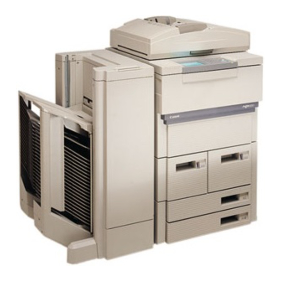
Page 30: Names Of Parts
Toner supply mouth Cassette 3 Original tray/Instructions tray Right deck Power switch Left deck Multifeeder Front door Upper right door Cassette eject button Figure 1-301 1-10 COPYRIGHT © 1997 CANON INC. CANON NP6560/NP6360/NP6260 REV.0 NOV. 1997 PRINTED IN JAPAN (IMPRIME AU JAPON) - Page 31 Holding tray feeding assembly knob Fixing feeding assembly Holding tray feeding assembly Fixing/feeding assembly lever Holding tray assembly Toner hopper Holding tray knob Figure 1-302 1-11 COPYRIGHT © 1997 CANON INC. CANON NP6560/NP6360/NP6260 REV.0 NOV. 1997 PRINTED IN JAPAN (IMPRIME AU JAPON)
-
Page 32: Cross Section
Lens No. 5 mirror Drum cleaning Multifeeder pick-up Holding tray pick-up assembly roller (crescent) roller Pre-exposure lamp Roller electrode Delivery roller Figure 1-303 1-12 COPYRIGHT © 1997 CANON INC. CANON NP6560/NP6360/NP6260 REV.0 NOV. 1997 PRINTED IN JAPAN (IMPRIME AU JAPON) -
Page 33: Operating The Machine
Interrupt key Start key Figure 1-401 Ready to copy. REDUCE DIRECT ENLARGE PAPERSELECT FIT IMAGE ZOOM SORTER 2-SIDED SPECIAL FEATURES LIGHT DARK Figure 1-402 1-13 COPYRIGHT © 1997 CANON INC. CANON NP6560/NP6360/NP6260 REV.0 NOV. 1997 PRINTED IN JAPAN (IMPRIME AU JAPON) -
Page 34: Extended Modes
Use it to select cover, back cover, or interleaf (20 sheets or less). Use it so that copying is possible only in response to a pre-regis- tered ID (1000 max.). Table 1-401 1-14 COPYRIGHT © 1997 CANON INC. CANON NP6560/NP6360/NP6260 REV.0 NOV. 1997 PRINTED IN JAPAN (IMPRIME AU JAPON) -
Page 35: User Mode
ON: Show size input screen. OFF: Do not show size input screen. Table 1-402(a) 1-15 COPYRIGHT © 1997 CANON INC. CANON NP6560/NP6360/NP6260 REV.0 NOV. 1997 PRINTED IN JAPAN (IMPRIME AU JAPON) - Page 36 Reset key (or in auto clear). You Copy ratio, may select factory default as post-initialization 100%; auto mode. paper select, ON; density control, manual; copy count, 1. Table 1-402(b) 1-16 COPYRIGHT © 1997 CANON INC. CANON NP6560/NP6360/NP6260 REV.0 NOV. 1997 PRINTED IN JAPAN (IMPRIME AU JAPON)
- Page 37 Time/Day Use it to set the time/day of the week for the built-in Used for the clock. weekly timer. Table 1-404 1-17 COPYRIGHT © 1997 CANON INC. CANON NP6560/NP6360/NP6260 REV.0 NOV. 1997 PRINTED IN JAPAN (IMPRIME AU JAPON)
- Page 38 [4] Preferences Item Description Remarks User Customize Use it to assign specific modes to keys on the 2 max. Standard screen. Table 1-405 1-18 COPYRIGHT © 1997 CANON INC. CANON NP6560/NP6360/NP6260 REV.0 NOV. 1997 PRINTED IN JAPAN (IMPRIME AU JAPON)
-
Page 39: Routine Maintenance By The User
Instruct the user to dispose of any empty toner bottle as nonflammable material. Caution: Do NOT throw the cartridges into fire; it can burst or explode. 1-19 COPYRIGHT © 1997 CANON INC. CANON NP6560/NP6360/NP6260 REV.0 NOV. 1997 PRINTED IN JAPAN (IMPRIME AU JAPON) -
Page 40: Image Formation
Fixing assembly assembly Roller electrode Pre-transfer charging assembly Pick-up (multifeeder) Separation claw Pick-up Transfer charging (cassette re-pick up) Separation assembly charging assembly Figure 1-601 1-20 COPYRIGHT © 1997 CANON INC. CANON NP6560/NP6360/NP6260 REV.0 NOV. 1997 PRINTED IN JAPAN (IMPRIME AU JAPON) - Page 41 4. Development Rotation of drum 9. Drum cleaning 5. Pre-transfer charging 6. Transfer Multifeeder Registration 7. Separation 8. Fixing Delivery Pick-up Figure 1-602 1-21 COPYRIGHT © 1997 CANON INC. CANON NP6560/NP6360/NP6260 REV.0 NOV. 1997 PRINTED IN JAPAN (IMPRIME AU JAPON)
- Page 42 CHAPTER 1 GENERAL DESCRIPTION 1-22 COPYRIGHT © 1997 CANON INC. CANON NP6560/NP6360/NP6260 REV.0 NOV. 1997 PRINTED IN JAPAN (IMPRIME AU JAPON)
-
Page 43: Basic Operation
B. Outline of the Electrical Circuitry...2-2 G. Inputs to and Outputs from C. Basic Sequence of Operations..2-4 Accessories (1/1)......2-31 D. Main Motor (M1) Control Circuitry..2-10 COPYRIGHT © 1997 CANON INC. CANON NP6560/NP6360/NP6260 REV.0 NOV. 1997 PRINTED IN JAPAN (IMPRIME AU JAPON) -
Page 45: Chapter 2 Basic Operation
Holding tray Holding tray inlet assembly Delivery control assembly Holding tray feeding assembly Cassette/paper deck Pick-up feeding assembly Figure 2-101 COPYRIGHT © 1997 CANON INC. CANON NP6560/NP6360/NP6260 REV.0 NOV. 1997 PRINTED IN JAPAN (IMPRIME AU JAPON) -
Page 46: Outline Of The Electrical Circuitry
IC on its DC controller PCB and the communications IC (IPC) on the controller PCB of each accessory. (IPC communication 2). Figure 2-102 is a block diagram which shows the relationship between the machine’s major circuits. COPYRIGHT © 1997 CANON INC. CANON NP6560/NP6360/NP6260 REV.0 NOV. 1997 PRINTED IN JAPAN (IMPRIME AU JAPON) - Page 47 Side deck driver Sensors/ deck switches (paper deck-A1) RDF controller PCB Sensors/ Micro- switches processor Sorter controller PCB Stapler Sensors/ Micro- sorter switches processor Figure 2-102 COPYRIGHT © 1997 CANON INC. CANON NP6560/NP6360/NP6260 REV.0 NOV. 1997 PRINTED IN JAPAN (IMPRIME AU JAPON)
-
Page 48: Basic Sequence Of Operations
(Cleaning is also executed every 2,000 copies.) *3 If the surface temperature of the fixing roller is 75°C or more. : Forward, : Reverse. Figure 2-103 COPYRIGHT © 1997 CANON INC. CANON NP6560/NP6360/NP6260 REV.0 NOV. 1997 PRINTED IN JAPAN (IMPRIME AU JAPON) - Page 49 • If the Copy Start key is pressed (auto start) during a wait period, copying starts at the end of LSTR. Table 2-101 COPYRIGHT © 1997 CANON INC. CANON NP6560/NP6360/NP6260 REV.0 NOV. 1997 PRINTED IN JAPAN (IMPRIME AU JAPON)
-
Page 50: Basic Sequence Of Operations
Scanning lamp (LA1) Developing clutch (CL1) *1 Turns off the blanking exposure LEDs corresponding to the potential sensor for potential measurement (V Figure 2-104 COPYRIGHT © 1997 CANON INC. CANON NP6560/NP6360/NP6260 REV.0 NOV. 1997 PRINTED IN JAPAN (IMPRIME AU JAPON) - Page 51 Discharges the last LSTR From the end of drum of charges as post sheet. SCRV to when the (last treatment. rotation) main motor stops. Table 2-102 COPYRIGHT © 1997 CANON INC. CANON NP6560/NP6360/NP6260 REV.0 NOV. 1997 PRINTED IN JAPAN (IMPRIME AU JAPON)
-
Page 52: Basic Sequence Of Operations In Page Separation Mode
Transfer charging assembly Separation charging assembly Blanking exposure LED lamp Right deck/cassette pick-up clutch (CL14) Scanning lamp (LA1) Forward Reverse Scanner Figure 2-105 COPYRIGHT © 1997 CANON INC. CANON NP6560/NP6360/NP6260 REV.0 NOV. 1997 PRINTED IN JAPAN (IMPRIME AU JAPON) - Page 53 • Transfers the toner turns off. image on the drum to copy paper. Note: For copy sequences other than the above, see Table 2-102. Table 2-103 COPYRIGHT © 1997 CANON INC. CANON NP6560/NP6360/NP6260 REV.0 NOV. 1997 PRINTED IN JAPAN (IMPRIME AU JAPON)
-
Page 54: Main Motor (M1) Control Circuitry
Mixing generator Frequency Main comparison motor Rotor Frequency J111 comparison -B4 M1ON MMCLK signal Q156 Master -B3 M1FG -11 1/4 division Figure 2-106 2-10 COPYRIGHT © 1997 CANON INC. CANON NP6560/NP6360/NP6260 REV.0 NOV. 1997 PRINTED IN JAPAN (IMPRIME AU JAPON) - Page 55 PCB will detect a fault in the clock pulses from the main motor and, as a result, will indi- cate ‘E010’ and an error message on the control panel. 2-11 COPYRIGHT © 1997 CANON INC. CANON NP6560/NP6360/NP6260 REV.0 NOV. 1997 PRINTED IN JAPAN (IMPRIME AU JAPON)
-
Page 56: Inputs To The Dc Controller
Holding tray feeding When PS9 has detected paper, '1'. J113-B12 assembly 2 paper PS9D (When the light-blocking plate is at PS9.) sensor Figure 2-107 2-12 COPYRIGHT © 1997 CANON INC. CANON NP6560/NP6360/NP6260 REV.0 NOV. 1997 PRINTED IN JAPAN (IMPRIME AU JAPON) - Page 57 '1'. re-circulating (When the light-blocking plate PS19 HPLPD lever home is at PS19.) position sensor Holding tray control PCB Figure 2-108 2-13 COPYRIGHT © 1997 CANON INC. CANON NP6560/NP6360/NP6260 REV.0 NOV. 1997 PRINTED IN JAPAN (IMPRIME AU JAPON)
- Page 58 When PS29 has detected paper, J815-1 J130-A8 Cassette 4 '1'. paper sensor PS29 C4PD (When the light-detecting plate is at PS29.) Figure 2-109 2-14 COPYRIGHT © 1997 CANON INC. CANON NP6560/NP6360/NP6260 REV.0 NOV. 1997 PRINTED IN JAPAN (IMPRIME AU JAPON)
- Page 59 When the left deck has reached Left deck limiter the limiter, '1'. LDEL PS39 sensor (When the light-blocking plate is at PS39.) Figure 2-110 2-15 COPYRIGHT © 1997 CANON INC. CANON NP6560/NP6360/NP6260 REV.0 NOV. 1997 PRINTED IN JAPAN (IMPRIME AU JAPON)
- Page 60 (When the light-blocking plate is sensor J108-B20 not at PS53.) +24V J103-B7 Potential POTON Sensor Potential See p. 4-4. measurement measurement sensor -B10 Figure 2-111 2-16 COPYRIGHT © 1997 CANON INC. CANON NP6560/NP6360/NP6260 REV.0 NOV. 1997 PRINTED IN JAPAN (IMPRIME AU JAPON)
- Page 61 MSW4 ('E013' is indicated.) locked detection Multifeeder J7251-1 24V From DC power supply unit. door switch MSW5 To HVT unit. detection Figure 2-112 2-17 COPYRIGHT © 1997 CANON INC. CANON NP6560/NP6360/NP6260 REV.0 NOV. 1997 PRINTED IN JAPAN (IMPRIME AU JAPON)
- Page 62 '0'. level detection When the holding tray unit is J202-1 J113- HTCNT* slid into the copier, '0'. Holding tray unit detection Figure 2-113 2-18 COPYRIGHT © 1997 CANON INC. CANON NP6560/NP6360/NP6260 REV.0 NOV. 1997 PRINTED IN JAPAN (IMPRIME AU JAPON)
- Page 63 (analog signal) Environment THHUM1 sensor When the humidity inside the machine increases, the voltage HUM1 decreases. (analog signal) Figure 2-114 2-19 COPYRIGHT © 1997 CANON INC. CANON NP6560/NP6360/NP6260 REV.0 NOV. 1997 PRINTED IN JAPAN (IMPRIME AU JAPON)
-
Page 64: Outputs From The Dc Controller
See p. 4-22. Thermal fuse MHOND SHOND J1-4 SHRD See p. 6-5. Thermal switch Fixing heater (main) MHRD Fixing heater (sub) Figure 2-115 2-20 COPYRIGHT © 1997 CANON INC. CANON NP6560/NP6360/NP6260 REV.0 NOV. 1997 PRINTED IN JAPAN (IMPRIME AU JAPON) - Page 65 From power supply unit J632-11 J778-3 J112-B2 M3FT M3CL M3BRK Scanner motor M3ON M3F/R M3MD2 M3MD1 -B10 M3MD0 -B11 M3FG -B12 M3FS Figure 2-116 2-21 COPYRIGHT © 1997 CANON INC. CANON NP6560/NP6360/NP6260 REV.0 NOV. 1997 PRINTED IN JAPAN (IMPRIME AU JAPON)
- Page 66 When '0', M6 rotates Transfer/separation J2737-1 J108-A1 TSCLM1 CW (forward). charging wire When '1', M6 rotates cleaning motor TSCLM2 CCW (reverse). Figure 2-117 2-22 COPYRIGHT © 1997 CANON INC. CANON NP6560/NP6360/NP6260 REV.0 NOV. 1997 PRINTED IN JAPAN (IMPRIME AU JAPON)
- Page 67 M9_HLD When '1', M9 stops. motor M9_B While the motor is rotating, alternates between '1' and '0'. Holding tray control PCB Figure 2-118 2-23 COPYRIGHT © 1997 CANON INC. CANON NP6560/NP6360/NP6260 REV.0 NOV. 1997 PRINTED IN JAPAN (IMPRIME AU JAPON)
- Page 68 When '1', M18 turns on. Right deck lifter motor -B12 J826-2 J119-B9 LDLMD When '1', M19 turns on. Left deck lifter motor -B10 Figure 2-119 2-24 COPYRIGHT © 1997 CANON INC. CANON NP6560/NP6360/NP6260 REV.0 NOV. 1997 PRINTED IN JAPAN (IMPRIME AU JAPON)
- Page 69 Scanner motor at 24 V, full speed rotation. cooling fan FM9ROT J781-2 J842-1 J201-1 Holding tray control From DC power supply unit Figure 2-120 2-25 COPYRIGHT © 1997 CANON INC. CANON NP6560/NP6360/NP6260 REV.0 NOV. 1997 PRINTED IN JAPAN (IMPRIME AU JAPON)
- Page 70 RGCD* When '0', CL9 turns on. J806-1 J805-1 J117-A1 Cassette 3 pick-up CL10 clutch C3PUCD* When '0', CL10 turns on. Figure 2-121 2-26 COPYRIGHT © 1997 CANON INC. CANON NP6560/NP6360/NP6260 REV.0 NOV. 1997 PRINTED IN JAPAN (IMPRIME AU JAPON)
- Page 71 0 drive CL18D* When '0', CL18 turns on. clutch J2756-6 J2755-24 J108-A16 Fixing brake CL19 clutch CL19D* When '0', CL19 turns on. Figure 2-122 2-27 COPYRIGHT © 1997 CANON INC. CANON NP6560/NP6360/NP6260 REV.0 NOV. 1997 PRINTED IN JAPAN (IMPRIME AU JAPON)
- Page 72 When '0', SL10 turns on fo -B12 SL10 SL10FD* solenoid normal direction. -B13 SL10BD* When '0', SL10 turns on fo reverse direction. Figure 2-123 2-28 COPYRIGHT © 1997 CANON INC. CANON NP6560/NP6360/NP6260 REV.0 NOV. 1997 PRINTED IN JAPAN (IMPRIME AU JAPON)
- Page 73 SL16 SL16FD* When '0', SL16 turns on solenoid -B14 SL16BD for normal direction. When '1'1, SL16 turns on for reverse direction. Figure 2-124 2-29 COPYRIGHT © 1997 CANON INC. CANON NP6560/NP6360/NP6260 REV.0 NOV. 1997 PRINTED IN JAPAN (IMPRIME AU JAPON)
- Page 74 LED2 J708-4 J706-5 J706-9 J103-A9 LED2DT* LED2CK* See p. 4-19. LED2LD* Blanking LED2ON* exposure -A10 J312-1 To DC power supply unit Figure 2-125 2-30 COPYRIGHT © 1997 CANON INC. CANON NP6560/NP6360/NP6260 REV.0 NOV. 1997 PRINTED IN JAPAN (IMPRIME AU JAPON)
-
Page 75: Inputs To And Outputs From Accessories (1/1)
24VA supply unit J726-3 J106-B3 CCNTD* When '0', CC-V turns on. Control card CC-V CCNNT* When '0', the card is detected. Figure 2-126 2-31 COPYRIGHT © 1997 CANON INC. CANON NP6560/NP6360/NP6260 REV.0 NOV. 1997 PRINTED IN JAPAN (IMPRIME AU JAPON) - Page 76 CHAPTER 2 BASIC OPERATION 2-32 COPYRIGHT © 1997 CANON INC. CANON NP6560/NP6360/NP6260 REV.0 NOV. 1997 PRINTED IN JAPAN (IMPRIME AU JAPON)
- Page 77 A. Movement of the Lens....3-2 A. Scanner Drive Assembly ....3-24 III. SCANNER DRIVE SYSTEM ....3-6 B. Lens Drive Assembly.....3-31 A. Scanner Movement .......3-6 COPYRIGHT © 1997 CANON INC. CANON NP6560/NP6360/NP6260 REV. 0 NOV. 1997 PRINTED IN JAPAN (IMPRIME AU JAPON)
-
Page 79: Chapter 3 Exposure System
The peripheral speed of the drum is the same as the speed of the movement of the mirror in Direct. Direct Reduce Enlarge Figure 3-101 COPYRIGHT © 1997 CANON INC. CANON NP6560/NP6360/NP6260 REV. 0 NOV. 1997 PRINTED IN JAPAN (IMPRIME AU JAPON) -
Page 80: Outline Of The Movement
Using the RDF Lens Original Coy paper (large) (large) Copy paper Original (small) (small) Figure 3-202 (top view) COPYRIGHT © 1997 CANON INC. CANON NP6560/NP6360/NP6260 REV. 0 NOV. 1997 PRINTED IN JAPAN (IMPRIME AU JAPON) -
Page 81: Moving The Lens
Micro- processor J736 J110 -A12 Y-HOLD Lens Y motor -A15 drive -A10 circuit -A11 M5A* Lens (Y) motor -A13 -A14 M5B* Figure 3-203 COPYRIGHT © 1997 CANON INC. CANON NP6560/NP6360/NP6260 REV. 0 NOV. 1997 PRINTED IN JAPAN (IMPRIME AU JAPON) -
Page 82: Moving The Lens
Lens X home position (PS6) Lens Y home position sensor (PS7) Motor CW/sensor ON Motor CCW Motor ON (direction depends on conditions) Figure 3-204 COPYRIGHT © 1997 CANON INC. CANON NP6560/NP6360/NP6260 REV. 0 NOV. 1997 PRINTED IN JAPAN (IMPRIME AU JAPON) - Page 83 (M5) Signal plate Lens X motor (M4) Y direction Lens X home position sensor (PS6) Enlarge Reduce DC controller PCB Figure 3-205 COPYRIGHT © 1997 CANON INC. CANON NP6560/NP6360/NP6260 REV. 0 NOV. 1997 PRINTED IN JAPAN (IMPRIME AU JAPON)
-
Page 84: Scanner Drive System
1 sensor (PS3) Scanner home position sensor (PS1) No. 1 mirror mount Forward No. 2/No. 3 mirror mount DC controller PCB Figure 3-301 COPYRIGHT © 1997 CANON INC. CANON NP6560/NP6360/NP6260 REV. 0 NOV. 1997 PRINTED IN JAPAN (IMPRIME AU JAPON) -
Page 85: Relationship Between The Scanner Sensors And The Signals
Scanner leading SCDP2 • Indicates that the scanner has edge 2 sensor reached stream reading (PS4) position. Table 3-301 COPYRIGHT © 1997 CANON INC. CANON NP6560/NP6360/NP6260 REV. 0 NOV. 1997 PRINTED IN JAPAN (IMPRIME AU JAPON) -
Page 86: Controlling The Scanner Motor Brake
A sample scan is made if the copyboard cover open/closed detecting lever is pressed by a tool or the copyboard cover pen/closed sensor (PS5) is blocked. To avoid injuries, do not service under such conditions. COPYRIGHT © 1997 CANON INC. CANON NP6560/NP6360/NP6260 REV. 0 NOV. 1997 PRINTED IN JAPAN (IMPRIME AU JAPON) - Page 87 *1 Moves the lens according to the selected reproduction ratio and copy size. *2 The degree of braking is automatically adjusted . Figure 3-302 COPYRIGHT © 1997 CANON INC. CANON NP6560/NP6360/NP6260 REV. 0 NOV. 1997 PRINTED IN JAPAN (IMPRIME AU JAPON)
-
Page 88: Movement Of The Scanner In Page Separation Mode
If the 1st and the 2nd pages are reversed using extended mode (Chapter 1), no change will occur except that the order of SCFW2/SCRV2 and SCFW1/SCRV1 is reversed. 3-10 COPYRIGHT © 1997 CANON INC. CANON NP6560/NP6360/NP6260 REV. 0 NOV. 1997 PRINTED IN JAPAN (IMPRIME AU JAPON) - Page 89 • RDF in use Size of original detected by feeder • Original frame Size of original specified by user erase mode Table 3-303 3-11 COPYRIGHT © 1997 CANON INC. CANON NP6560/NP6360/NP6260 REV. 0 NOV. 1997 PRINTED IN JAPAN (IMPRIME AU JAPON)
-
Page 90: Movement Of The Scanner With The Rdf In Use (A4, 2 Originals, 1 Copy)
The use of stream reading enables omission of the scanner reverse period, thereby reducing the sheet-to-sheet distance and, ultimately, enabling a copying speed of 65 copies/minute (A4, LTR). 3-12 COPYRIGHT © 1997 CANON INC. CANON NP6560/NP6360/NP6260 REV. 0 NOV. 1997 PRINTED IN JAPAN (IMPRIME AU JAPON) - Page 91 The 1st original is delivered from the The 2nd original is delivered from the left. left. Figure 3-305 3-13 COPYRIGHT © 1997 CANON INC. CANON NP6560/NP6360/NP6260 REV. 0 NOV. 1997 PRINTED IN JAPAN (IMPRIME AU JAPON)
-
Page 92: Movement Of The Scanner With The Rdf In Use (A4, 2 Copies)
Immediately after stream reading, the original is stopped on the copyboard glass, and the remaining sets of copies are made in normal scanning mode (moving scanner). 3-14 COPYRIGHT © 1997 CANON INC. CANON NP6560/NP6360/NP6260 REV. 0 NOV. 1997 PRINTED IN JAPAN (IMPRIME AU JAPON) - Page 93 11) The 1st original is delivered. reading has ended. The scanner returns illuminate the remaining number of originals. to home position. Figure 3-307 3-15 COPYRIGHT © 1997 CANON INC. CANON NP6560/NP6360/NP6260 REV. 0 NOV. 1997 PRINTED IN JAPAN (IMPRIME AU JAPON)
- Page 94 CHAPTER 3 EXPOSURE SYSTEM 3-16 COPYRIGHT © 1997 CANON INC. CANON NP6560/NP6360/NP6260 REV. 0 NOV. 1997 PRINTED IN JAPAN (IMPRIME AU JAPON)
-
Page 95: Scanner Motor (M3) Control Circuit
J112 J632 M3CL Motor rotation SCMCLK M3MD2 speed M3MD1 control circuit -B10 M3MD0 J112 J632 -B11 M3FS J112 -B12 M3FG Figure 3-308 3-17 COPYRIGHT © 1997 CANON INC. CANON NP6560/NP6360/NP6260 REV. 0 NOV. 1997 PRINTED IN JAPAN (IMPRIME AU JAPON) - Page 96 PCB is varied as shown in Table 3-304. M3MD2 M3MD1 M3MD0 One-sided copying 204~172 171~144 143~120 119~100 99~79 78~62 61~49 Scanner reverse Table 3-304 3-18 COPYRIGHT © 1997 CANON INC. CANON NP6560/NP6360/NP6260 REV. 0 NOV. 1997 PRINTED IN JAPAN (IMPRIME AU JAPON)
- Page 97 Scanner stop signal Scanner home position sensor Scanner original leading edge 1 sensor *1 Brakes to slow down. *2 Brakes to stop. Figure 3-309 3-19 COPYRIGHT © 1997 CANON INC. CANON NP6560/NP6360/NP6260 REV. 0 NOV. 1997 PRINTED IN JAPAN (IMPRIME AU JAPON)
-
Page 98: Others
3 signal 0 Original detection signal 1 Original detection signal 2 Copyboard cover detection signal 1 DC controller PCB Figure 3-401 3-20 COPYRIGHT © 1997 CANON INC. CANON NP6560/NP6360/NP6260 REV. 0 NOV. 1997 PRINTED IN JAPAN (IMPRIME AU JAPON) -
Page 99: Operation
PS5 has turned on against the slice level. 2. If the copyboard cover is opened (PS5 is off), the cassette containing the maxi- mum size paper will be selected. 3-21 COPYRIGHT © 1997 CANON INC. CANON NP6560/NP6360/NP6260 REV. 0 NOV. 1997 PRINTED IN JAPAN (IMPRIME AU JAPON) -
Page 100: Size Of Originals
Table 3-401 Inch Configuration Original detection signal Size Inch Sensor 2 Sensor 1 Sensor 0 None LTRR 279.4mm 431.8mm (11" 17") Table 3-402 3-22 COPYRIGHT © 1997 CANON INC. CANON NP6560/NP6360/NP6260 REV. 0 NOV. 1997 PRINTED IN JAPAN (IMPRIME AU JAPON) -
Page 101: Disassembly And Assembly
7. Before sliding out the duplexing unit or the fixing assembly, check to make sure that the front door switch or the power switch is off. 3-23 COPYRIGHT © 1997 CANON INC. CANON NP6560/NP6360/NP6260 REV. 0 NOV. 1997 PRINTED IN JAPAN (IMPRIME AU JAPON) -
Page 102: Scanner Drive Assembly
; then, remove the RDF rear right mount Figure 3-502 8) Remove the mounting screw and remove the RDF/copyboard cover detection assembly Figure 3-503 3-24 COPYRIGHT © 1997 CANON INC. CANON NP6560/NP6360/NP6260 REV. 0 NOV. 1997 PRINTED IN JAPAN (IMPRIME AU JAPON) - Page 103 When removing the scanner drive motor assembly, be sure to mark the edge of the motor assembly in advance. 3-25 COPYRIGHT © 1997 CANON INC. CANON NP6560/NP6360/NP6260 REV. 0 NOV. 1997 PRINTED IN JAPAN (IMPRIME AU JAPON)
-
Page 104: Routing The Scanner Drive Cable
3. Orienting the Heat Absorbing Glass White paint (rear) Be sure to orient the heat absorbing glass whenever replacing the heat absorbing glass. (front) Figure 3-505a 3-26 COPYRIGHT © 1997 CANON INC. CANON NP6560/NP6360/NP6260 REV. 0 NOV. 1997 PRINTED IN JAPAN (IMPRIME AU JAPON) -
Page 105: Removing The Scanner Drive Cable
; then, remove the scanner cooling fan Figure 3-507 8) Remove the two cable fixing screws (rear) from the No. 1 mirror mount. Figure 3-508 3-27 COPYRIGHT © 1997 CANON INC. CANON NP6560/NP6360/NP6260 REV. 0 NOV. 1997 PRINTED IN JAPAN (IMPRIME AU JAPON) - Page 106 (front) from the No. 1 mirror mount. Figure 3-509 10) Loosen the tension screw loosen the scanner cable. 11) Remove the scanner cable. Figure 3-510 3-28 COPYRIGHT © 1997 CANON INC. CANON NP6560/NP6360/NP6260 REV. 0 NOV. 1997 PRINTED IN JAPAN (IMPRIME AU JAPON)
-
Page 107: Adjusting The Tension Of The Scanner Drive Cable
3) Loosen the two screws on the metal clamps used to fix the scanner drive cable to the No. 1 mirror mount. 4) Remove the tool. Figure 3-513 3-29 COPYRIGHT © 1997 CANON INC. CANON NP6560/NP6360/NP6260 REV. 0 NOV. 1997 PRINTED IN JAPAN (IMPRIME AU JAPON) -
Page 108: Positioning The Scanner Locking Solenoid (Sl1)
8.5 ±0.5 mm (from below clamp to top of solenoid) Scanner locking solenoid (SL1) Loosen these two screws to adjust once again. Figure 3-514 3-30 COPYRIGHT © 1997 CANON INC. CANON NP6560/NP6360/NP6260 REV. 0 NOV. 1997 PRINTED IN JAPAN (IMPRIME AU JAPON) -
Page 109: Lens Drive Assembly
Figure 3-515 3-31 COPYRIGHT © 1997 CANON INC. CANON NP6560/NP6360/NP6260 REV. 0 NOV. 1997 PRINTED IN JAPAN (IMPRIME AU JAPON) - Page 110 2) Move the No. 1 mirror mount to the left of the scanner rail. Caution: Be sure to push the center of the No. 1 mirror mount. 3-32 COPYRIGHT © 1997 CANON INC. CANON NP6560/NP6360/NP6260 REV. 0 NOV. 1997 PRINTED IN JAPAN (IMPRIME AU JAPON)
- Page 111 Figure 3-519 7) Lift the lens stage , and detach the bushing from the rail Figure 3-520 3-33 COPYRIGHT © 1997 CANON INC. CANON NP6560/NP6360/NP6260 REV. 0 NOV. 1997 PRINTED IN JAPAN (IMPRIME AU JAPON)
-
Page 112: Installing The Light-Blocking Belt Mount
Figure 3-522 3) Remove the two mounting screws ; then, detach the lens X direction motor from the motor mount. Figure 3-523 3-34 COPYRIGHT © 1997 CANON INC. CANON NP6560/NP6360/NP6260 REV. 0 NOV. 1997 PRINTED IN JAPAN (IMPRIME AU JAPON) -
Page 113: Attaching The Lens X Direction Drive Belt
Own weight Figure 3-524 6. Routing the Light-Blocking Belt Light-blocking belt 1 Light-blocking belt 3 Light-blocking belt 2 Light-blocking belt 4 Figure 3-525 3-35 COPYRIGHT © 1997 CANON INC. CANON NP6560/NP6360/NP6260 REV. 0 NOV. 1997 PRINTED IN JAPAN (IMPRIME AU JAPON) - Page 114 3) Remove the two screws , and remove the light-blocking plate while lifting the lens stage Figure 3-527 3-36 COPYRIGHT © 1997 CANON INC. CANON NP6560/NP6360/NP6260 REV. 0 NOV. 1997 PRINTED IN JAPAN (IMPRIME AU JAPON)
- Page 115 B. Detecting the Level of Toner and O. Waste Toner Feeding Assembly..4-66 Controlling the Supply Operation ..4-30 C. Controlling the Developing Bias/Roller Electrode .....4-32 COPYRIGHT © 1997 CANON INC. CANON NP6560/NP6360/NP6260 REV. 0 NOV. 1997 PRINTED IN JAPAN (IMPRIME AU JAPON)
-
Page 117: Chapter 4 Image Formation System
Cleaning screw Developing cylinder Cleaning roller Pre-transfer charging assembly Copy paper Separation charging wire Transfer charging assembly High-voltage transformer DC controller PCB Figure 4-101 COPYRIGHT © 1997 CANON INC. CANON NP6560/NP6360/NP6260 REV. 0 NOV. 1997 PRINTED IN JAPAN (IMPRIME AU JAPON) -
Page 118: Control Method
60 min of power-on. Photo mode • Once while making the first copy in photo mode after power-on. Table 4-102 Timing of Potential Control COPYRIGHT © 1997 CANON INC. CANON NP6560/NP6360/NP6260 REV. 0 NOV. 1997 PRINTED IN JAPAN (IMPRIME AU JAPON) - Page 119 The DC controller PCB compares the measurement against the target value; if there is a discrepancy, the intensity adjustment signal (LINT) from the DC controller PCB is corrected, and the potential is measured once again. COPYRIGHT © 1997 CANON INC. CANON NP6560/NP6360/NP6260 REV. 0 NOV. 1997 PRINTED IN JAPAN (IMPRIME AU JAPON)
-
Page 120: Potential Measurement Circuit
The sensor and the potential measurement PCB are adjusted to a high precision as a pair, and cannot be adjusted in the field. They are treated as a single entity ser- vice part. COPYRIGHT © 1997 CANON INC. CANON NP6560/NP6360/NP6260 REV. 0 NOV. 1997 PRINTED IN JAPAN (IMPRIME AU JAPON) - Page 121 Sensor drive circuit DC controller PCB Drum surface potential detection circuit High-voltage Level Micro- generation/ transformer shift processor adjustment circuit circuit circuit Figure 4-104 COPYRIGHT © 1997 CANON INC. CANON NP6560/NP6360/NP6260 REV. 0 NOV. 1997 PRINTED IN JAPAN (IMPRIME AU JAPON)
-
Page 122: Controlling The Intensity Of The Scanning Lamp
(master) phase control power voltage J111 circuit LAON J503-2 Arc circuit J501-1 DC controller PCB Lamp regulator PCB Figure 4-105 COPYRIGHT © 1997 CANON INC. CANON NP6560/NP6360/NP6260 REV. 0 NOV. 1997 PRINTED IN JAPAN (IMPRIME AU JAPON) -
Page 123: Operation
AE mode may be executed on the copier side or the RDF side, the latter of which is used when originals are placed in the RDF. The copier’s AE mode is used, however, when manual feeding is selected. COPYRIGHT © 1997 CANON INC. CANON NP6560/NP6360/NP6260 REV. 0 NOV. 1997 PRINTED IN JAPAN (IMPRIME AU JAPON) - Page 124 AE sensor 1 (S7) is used for left pick-up, while AE sensor 2 (S33) is used for right pick-up (Figure 4-108). AE sensor (S7) AE sensor 2 (S33) Figure 4-108 COPYRIGHT © 1997 CANON INC. CANON NP6560/NP6360/NP6260 REV. 0 NOV. 1997 PRINTED IN JAPAN (IMPRIME AU JAPON)
- Page 125 (b) Right Pick-Up (a) Left Pick-Up Figure 4-109 Points of Measurement on an Original equivalent equivalent Original Lighter Darker density Test Sheet Newspaper Figure 4-110 COPYRIGHT © 1997 CANON INC. CANON NP6560/NP6360/NP6260 REV. 0 NOV. 1997 PRINTED IN JAPAN (IMPRIME AU JAPON)
-
Page 126: Making Checks
When the setting is Copy decreased in adjust- density ment mode, the copy of a newspaper will be Input lighter. Table 4-103 4-10 COPYRIGHT © 1997 CANON INC. CANON NP6560/NP6360/NP6260 REV. 0 NOV. 1997 PRINTED IN JAPAN (IMPRIME AU JAPON) -
Page 127: Controlling The Primary/Transfer Corona Current
HVRMT is ‘0’ Variable width pulse oscillator circuit goes OFF. Comparator circuit goes OFF. Drive circuit goes OFF. Primary high-voltage transformer goes OFF. 4-11 COPYRIGHT © 1997 CANON INC. CANON NP6560/NP6360/NP6260 REV. 0 NOV. 1997 PRINTED IN JAPAN (IMPRIME AU JAPON) - Page 128 ) used in normal copying mode. As such, potential control is executed while making the first copy in photo mode after power-on to control the primary corona current. 4-12 COPYRIGHT © 1997 CANON INC. CANON NP6560/NP6360/NP6260 REV. 0 NOV. 1997 PRINTED IN JAPAN (IMPRIME AU JAPON)
-
Page 129: Controlling The Transfer Corona Current
HVTCT is about 12 V. HVRMT is ‘0’. Comparator circuit goes OFF. Variable width pulse oscillator goes OFF. Drive circuit goes OFF. Primary transformer goes OFF. 4-13 COPYRIGHT © 1997 CANON INC. CANON NP6560/NP6360/NP6260 REV. 0 NOV. 1997 PRINTED IN JAPAN (IMPRIME AU JAPON) - Page 130 4-14 COPYRIGHT © 1997 CANON INC. CANON NP6560/NP6360/NP6260 REV. 0 NOV. 1997 PRINTED IN JAPAN (IMPRIME AU JAPON)
-
Page 131: Controlling The Separation/Pre-Transfer Corona Current
Overcurrent detection J114 J779 circuit DC transformerT302 HVSCT Constant Switching Drive current control circuit circuit circuit J114 J779 DCPC Figure 4-113 4-15 COPYRIGHT © 1997 CANON INC. CANON NP6560/NP6360/NP6260 REV. 0 NOV. 1997 PRINTED IN JAPAN (IMPRIME AU JAPON) -
Page 132: Turning On And Off The Separation/Pre-Transfer Corona Current
HVTAC drive signal (ACON), roller electrode rive signal (ROED), and high-voltage remote signal (HVRMT) generated by the DC controller PCB go ‘1’. 4-16 COPYRIGHT © 1997 CANON INC. CANON NP6560/NP6360/NP6260 REV. 0 NOV. 1997 PRINTED IN JAPAN (IMPRIME AU JAPON) -
Page 133: Separation Corona Current
The level of the pre-transfer corona current (DC component) is varied according to the voltage level of DCPC. Pre-transfer corona current (µA) -330 Voltage level (V) of DCPC Figure 4-117 4-17 COPYRIGHT © 1997 CANON INC. CANON NP6560/NP6360/NP6260 REV. 0 NOV. 1997 PRINTED IN JAPAN (IMPRIME AU JAPON) -
Page 134: Controlling The Dc Component Of The Separation/Pre-Transfer Corona Current
Separation OFF ‘0’ ‘0’ ‘0’ ‘0’ — *Output from the DC controller PCB (connector of signal name). Table 4-104 Combinations of Transfer/Separation Signals 4-18 COPYRIGHT © 1997 CANON INC. CANON NP6560/NP6360/NP6260 REV. 0 NOV. 1997 PRINTED IN JAPAN (IMPRIME AU JAPON) -
Page 135: Controlling The Blanking Exposure Lamp (Led)
‘free’, on the other hand, frame erasing will be executed using the maximum size (297 mm). 4-19 COPYRIGHT © 1997 CANON INC. CANON NP6560/NP6360/NP6260 REV. 0 NOV. 1997 PRINTED IN JAPAN (IMPRIME AU JAPON) -
Page 136: Controlling The Activation In Original Frame Erase Mode
(standard) along the middle of the paper. (The width may be adjusted to 20 ±10 mm in service mode.) 20 mm 2 mm (approx.) 2 mm (approx.) Figure 4-119 4-20 COPYRIGHT © 1997 CANON INC. CANON NP6560/NP6360/NP6260 REV. 0 NOV. 1997 PRINTED IN JAPAN (IMPRIME AU JAPON) -
Page 137: Controlling The Activation In Hole Image Erase Mode
LEDs that are over the area of measurement are turned with the remaining LEDs kept on. Blank exposure lamp (LEDs) Potential sensor Photosensitive drum Figure 4-121 4-21 COPYRIGHT © 1997 CANON INC. CANON NP6560/NP6360/NP6260 REV. 0 NOV. 1997 PRINTED IN JAPAN (IMPRIME AU JAPON) -
Page 138: Drum Heater Circuit
‘0’, turning off the drum heater. Drum surface temperature: 42°C Thermal fuse rated temperature: 76°C 4-22 COPYRIGHT © 1997 CANON INC. CANON NP6560/NP6360/NP6260 REV. 0 NOV. 1997 PRINTED IN JAPAN (IMPRIME AU JAPON) - Page 139 J641-3 Drum heater DHRD drive circuit FU601 Comparison circuit Drum Trigger circuit heater Triac Thermistor Drum heater controller PCB J01-1 Figure 4-122 4-23 COPYRIGHT © 1997 CANON INC. CANON NP6560/NP6360/NP6260 REV. 0 NOV. 1997 PRINTED IN JAPAN (IMPRIME AU JAPON)
-
Page 140: Idle Rotation Of The Photosensitive Drum And The Developing Cylinder
Up to 6 min Table 4-107 Reference: The 100V machines are shipped with the drum heater switch (SW3) set to ON (idle rotation mode ON). 4-24 COPYRIGHT © 1997 CANON INC. CANON NP6560/NP6360/NP6260 REV. 0 NOV. 1997 PRINTED IN JAPAN (IMPRIME AU JAPON) -
Page 141: Cleaning The Primary Charging Wire
Wire cleaner Primary charging wire cleaning moter drive command DC controller PCB (PCLM) J103-B3, B4 Primary charging wire cleaning moter (M12) Figure 4-123 4-25 COPYRIGHT © 1997 CANON INC. CANON NP6560/NP6360/NP6260 REV. 0 NOV. 1997 PRINTED IN JAPAN (IMPRIME AU JAPON) -
Page 142: Pre-Transfer/Transfer/Separation Charging Wire Automatic Cleaning Mechanism
DC controller PCB Feeding screw Pre-transfer charging wire Pre-transfer charging wire cleaning motor (M 13) Wire Wire cleaner Figure 4-124 (pre-transfer charging assembly) 4-26 COPYRIGHT © 1997 CANON INC. CANON NP6560/NP6360/NP6260 REV. 0 NOV. 1997 PRINTED IN JAPAN (IMPRIME AU JAPON) - Page 143 CHAPTER 4 IMAGE FORMATION SYSTEM Transfer/separation charging wire DC controller PCB Wire Wire cleaner Transfer/separation charging wire cleaner motor (M6) Figure 4-125 (transfer/separation charging assembly) 4-27 COPYRIGHT © 1997 CANON INC. CANON NP6560/NP6360/NP6260 REV. 0 NOV. 1997 PRINTED IN JAPAN (IMPRIME AU JAPON)
-
Page 144: Drum Cleaning Assembly/Developing Assembly
The waste toner feeding assembly is equipped with a torque limiter. If the screw becomes clogged with waste toner, the waste toner feeding screw detection circuit turns on to turn off the main motor (M1). 4-28 COPYRIGHT © 1997 CANON INC. CANON NP6560/NP6360/NP6260 REV. 0 NOV. 1997 PRINTED IN JAPAN (IMPRIME AU JAPON) - Page 145 TS 2 Photosensitive drum Waste toner feeding pipe Developing clutch Main motor Waste toner case DC controller PCB Figure 4-201 4-29 COPYRIGHT © 1997 CANON INC. CANON NP6560/NP6360/NP6260 REV. 0 NOV. 1997 PRINTED IN JAPAN (IMPRIME AU JAPON)
-
Page 146: Detecting The Level Of Toner And Controlling The Supply Operation
*3 Drives the hopper for 2.0 sec and then holds it for 1 sec, supplying toner by repeating this sequence. Figure 4-202 4-30 COPYRIGHT © 1997 CANON INC. CANON NP6560/NP6360/NP6260 REV. 0 NOV. 1997 PRINTED IN JAPAN (IMPRIME AU JAPON) - Page 147 Otherwise, the toner collecting in the path from the hopper to the developing assembly can pour out because of the vibrations caused by inspection/repair work. 4-31 COPYRIGHT © 1997 CANON INC. CANON NP6560/NP6360/NP6260 REV. 0 NOV. 1997 PRINTED IN JAPAN (IMPRIME AU JAPON)
-
Page 148: Controlling The Developing Bias/Roller Electrode
SCFW, SCRV To prevent fogging of the background. during copying AC component 1500 Vp-p, To execute toner projection. 2700 Hz Table 4-201 4-32 COPYRIGHT © 1997 CANON INC. CANON NP6560/NP6360/NP6260 REV. 0 NOV. 1997 PRINTED IN JAPAN (IMPRIME AU JAPON) - Page 149 Developing clutch (CL8) DC bias AC bias DC bias : : +600 V : Potential control value (V + 100 V) Figure 4-206 4-33 COPYRIGHT © 1997 CANON INC. CANON NP6560/NP6360/NP6260 REV. 0 NOV. 1997 PRINTED IN JAPAN (IMPRIME AU JAPON)
- Page 150 Main motor (M1) Developing clutch (CL8) DC bias AC bias DC bias: : +600V : Potential control value (V + 100 V) Figure 4-207 4-34 COPYRIGHT © 1997 CANON INC. CANON NP6560/NP6360/NP6260 REV. 0 NOV. 1997 PRINTED IN JAPAN (IMPRIME AU JAPON)
-
Page 151: Developing Bias Control Circuit
Micro- processor HVRMT Roller electrode DC transformer T402 J114 J779 Switch Drive circuit circuit ROED J114 J779 converter DCBC Figure 4-208 4-35 COPYRIGHT © 1997 CANON INC. CANON NP6560/NP6360/NP6260 REV. 0 NOV. 1997 PRINTED IN JAPAN (IMPRIME AU JAPON) -
Page 152: Roller Electrode Bias Control Circuit
The above condition supplies the roller electrode with a bias of about 1000 V; the DC bias is not controlled to a specific voltage. 4-36 COPYRIGHT © 1997 CANON INC. CANON NP6560/NP6360/NP6260 REV. 0 NOV. 1997 PRINTED IN JAPAN (IMPRIME AU JAPON) - Page 153 ‘0’ ‘0’ — * Output from the DC controller PCB (connector No.). Table 4-202 Combination of Developing DC/Roller Electrode Bias Output Signals 4-37 COPYRIGHT © 1997 CANON INC. CANON NP6560/NP6360/NP6260 REV. 0 NOV. 1997 PRINTED IN JAPAN (IMPRIME AU JAPON)
-
Page 154: Detecting The Waste Toner Feeding Screw (Locking)
When the waste toner feeding screw becomes locked, the gear A will slide in the direction of the arrow. Waste toner Figure 4-210 (rear view) 4-38 COPYRIGHT © 1997 CANON INC. CANON NP6560/NP6360/NP6260 REV. 0 NOV. 1997 PRINTED IN JAPAN (IMPRIME AU JAPON) -
Page 155: Disassembly And Assembly
7. Before sliding out the duplexing unit or the fixing assembly, check to make sure that the front door switch or the power switch is off. Do NOT throw the toner into fire; it can explode. 4-39 COPYRIGHT © 1997 CANON INC. CANON NP6560/NP6360/NP6260 REV. 0 NOV. 1997 PRINTED IN JAPAN (IMPRIME AU JAPON) -
Page 156: Scanning Lamp Assembly
4-40 COPYRIGHT © 1997 CANON INC. CANON NP6560/NP6360/NP6260 REV. 0 NOV. 1997 PRINTED IN JAPAN (IMPRIME AU JAPON) -
Page 157: Removing The Thermal Fuse
, and remove the copyboard glass right retaining plate Figure 4-304 4) Remove the two stepped screws (M3x3), and remove the standard white cover Figure 4-305 4-41 COPYRIGHT © 1997 CANON INC. CANON NP6560/NP6360/NP6260 REV. 0 NOV. 1997 PRINTED IN JAPAN (IMPRIME AU JAPON) -
Page 158: Pre-Exposure Lamp Unit
4) Remove the blanking exposure lamp assembly. 5) Remove the two mounting screws , and remove the blanking expo- sure assembly rail stay 4-42 COPYRIGHT © 1997 CANON INC. CANON NP6560/NP6360/NP6260 REV. 0 NOV. 1997 PRINTED IN JAPAN (IMPRIME AU JAPON) -
Page 159: Blanking Exposure Lamp Assembly
Caution: When removing the blanking expo- sure lamp assembly, take care so Figure 4-310 as not to damage the photosensi- tive drum. 4-43 COPYRIGHT © 1997 CANON INC. CANON NP6560/NP6360/NP6260 REV. 0 NOV. 1997 PRINTED IN JAPAN (IMPRIME AU JAPON) -
Page 160: Photosensitive Drum
5) Remove the blanking exposure assembly rail stay. 6) Remove the three mounting screws Figure 4-311 , and remove the gear plate 4-44 COPYRIGHT © 1997 CANON INC. CANON NP6560/NP6360/NP6260 REV. 0 NOV. 1997 PRINTED IN JAPAN (IMPRIME AU JAPON) - Page 161 You need not remove the bearing at the rear and the gear at the front of the photosensitive drum. Figure 4-313 4-45 COPYRIGHT © 1997 CANON INC. CANON NP6560/NP6360/NP6260 REV. 0 NOV. 1997 PRINTED IN JAPAN (IMPRIME AU JAPON)
-
Page 162: Replacing The Drum Heater
(See p. 4-43.) Caution: Keep in mind that the potential sensor assembly is an integrated part of the blanking exposure lamp assembly. 4-46 COPYRIGHT © 1997 CANON INC. CANON NP6560/NP6360/NP6260 REV. 0 NOV. 1997 PRINTED IN JAPAN (IMPRIME AU JAPON) -
Page 163: Primary Charging Assembly
100°C or less, since wire cleaning will be executed automat- Figure 4-316 ically.) 4-47 COPYRIGHT © 1997 CANON INC. CANON NP6560/NP6360/NP6260 REV. 0 NOV. 1997 PRINTED IN JAPAN (IMPRIME AU JAPON) -
Page 164: Transfer/Separation Charging Assembly
, and slide out the transfer/separation charging assembly to the front; then, remove it by lifting it toward the left. Figure 4-318 4-48 COPYRIGHT © 1997 CANON INC. CANON NP6560/NP6360/NP6260 REV. 0 NOV. 1997 PRINTED IN JAPAN (IMPRIME AU JAPON) -
Page 165: Separation Charging Assembly
(when sliding it from the front). Figure 4-320 Figure 4-321 4-49 COPYRIGHT © 1997 CANON INC. CANON NP6560/NP6360/NP6260 REV. 0 NOV. 1997 PRINTED IN JAPAN (IMPRIME AU JAPON) - Page 166 100°C or less, since wire cleaning will be exe- cuted automatically.) 4-50 COPYRIGHT © 1997 CANON INC. CANON NP6560/NP6360/NP6260 REV. 0 NOV. 1997 PRINTED IN JAPAN (IMPRIME AU JAPON)
-
Page 167: Charging Wire
(i.e., do not loosen the mounting screws Figure 4-324 both plates at the same time). 2) Remove the wire cleaner. 4-51 COPYRIGHT © 1997 CANON INC. CANON NP6560/NP6360/NP6260 REV. 0 NOV. 1997 PRINTED IN JAPAN (IMPRIME AU JAPON) - Page 168 In the case of the transfer charging Figure 4-327 assembly, hook it on the pin at the front. 4-52 COPYRIGHT © 1997 CANON INC. CANON NP6560/NP6360/NP6260 REV. 0 NOV. 1997 PRINTED IN JAPAN (IMPRIME AU JAPON)
-
Page 169: Stringing The Grid Wire Of The Primary Charging Assembly
2) Loosen the three mounting screws used to keep the motor unit at the front in place. Figure 4-329 4-53 COPYRIGHT © 1997 CANON INC. CANON NP6560/NP6360/NP6260 REV. 0 NOV. 1997 PRINTED IN JAPAN (IMPRIME AU JAPON) - Page 170 Check to make sure that the wire is strung at equal intervals (i.e., it is in the groove of the block). 4-54 COPYRIGHT © 1997 CANON INC. CANON NP6560/NP6360/NP6260 REV. 0 NOV. 1997 PRINTED IN JAPAN (IMPRIME AU JAPON)
- Page 171 A full turn of the screw changes the position of the charg- ing wire by about 0.7 mm. 4-55 COPYRIGHT © 1997 CANON INC. CANON NP6560/NP6360/NP6260 REV. 0 NOV. 1997 PRINTED IN JAPAN (IMPRIME AU JAPON)
-
Page 172: Cleaning The Primary Charging Assembly Anti-Stray Sheet
5) Remove the two screws , and remove the blanking exposure rail stay Figure 4-333 6) Clean the primary charging assem- bly anti-stray sheet Figure 4-334 4-56 COPYRIGHT © 1997 CANON INC. CANON NP6560/NP6360/NP6260 REV. 0 NOV. 1997 PRINTED IN JAPAN (IMPRIME AU JAPON) -
Page 173: Developing Assembly
2) Remove the mounting screw , and push the developing assembly lock- ing assembly in the direction of the arrow to remove. Figure 4-335 4-57 COPYRIGHT © 1997 CANON INC. CANON NP6560/NP6360/NP6260 REV. 0 NOV. 1997 PRINTED IN JAPAN (IMPRIME AU JAPON) -
Page 174: Removing The Blade Unit
The blade must be installed to a Figure 4-338 very high precision. Do not remove it on its own in the field. (You must remove its mounting plate.) 4-58 COPYRIGHT © 1997 CANON INC. CANON NP6560/NP6360/NP6260 REV. 0 NOV. 1997 PRINTED IN JAPAN (IMPRIME AU JAPON) -
Page 175: Installing The Blade
, parallel pin and butting roll (one each). Figure 4-340 4-59 COPYRIGHT © 1997 CANON INC. CANON NP6560/NP6360/NP6260 REV. 0 NOV. 1997 PRINTED IN JAPAN (IMPRIME AU JAPON) - Page 176 Figure 4-342 7) Remove the grip ring mounted to the cylinder shaft at the front, and remove the butting roll Figure 4-343 4-60 COPYRIGHT © 1997 CANON INC. CANON NP6560/NP6360/NP6260 REV. 0 NOV. 1997 PRINTED IN JAPAN (IMPRIME AU JAPON)
- Page 177 (Do not use sol- vent.) 5. Cleaning Developing Assembly Anti-Stray Sheet 1) Remove the developing assembly, and clean the developing assembly anti-stray sheet Figure 4-346 4-61 COPYRIGHT © 1997 CANON INC. CANON NP6560/NP6360/NP6260 REV. 0 NOV. 1997 PRINTED IN JAPAN (IMPRIME AU JAPON)
-
Page 178: Hopper Assembly
AC line of the drum heater. 4) Remove the four mounting screws , and remove the cleaning blade assembly Figure 4-349 4-62 COPYRIGHT © 1997 CANON INC. CANON NP6560/NP6360/NP6260 REV. 0 NOV. 1997 PRINTED IN JAPAN (IMPRIME AU JAPON) -
Page 179: Installing The Cleaning Blade
1) Butt the cleaning blade against the rear. No gap. Blade retaining plate Figure 4-352 4-63 COPYRIGHT © 1997 CANON INC. CANON NP6560/NP6360/NP6260 REV. 0 NOV. 1997 PRINTED IN JAPAN (IMPRIME AU JAPON) -
Page 180: Installing The Side Seal
3) Fix the size seal (both front and rear) to the cleaner housing at the location indicated. Figure 4-354 4-64 COPYRIGHT © 1997 CANON INC. CANON NP6560/NP6360/NP6260 REV. 0 NOV. 1997 PRINTED IN JAPAN (IMPRIME AU JAPON) - Page 181 (viewing from the front). 5) When the area from which toner was removed in step 3) is everly coated, repeat steps 3) through 5). 4-65 COPYRIGHT © 1997 CANON INC. CANON NP6560/NP6360/NP6260 REV. 0 NOV. 1997 PRINTED IN JAPAN (IMPRIME AU JAPON)
-
Page 182: Separation Claw/Separation Claw Drive Assembly
6) Remove the mounting screw , and remove the waste toner feeding screw detection circuit Figure 4-357 4-66 COPYRIGHT © 1997 CANON INC. CANON NP6560/NP6360/NP6260 REV. 0 NOV. 1997 PRINTED IN JAPAN (IMPRIME AU JAPON) - Page 183 7) Remove the two mounting screws , and remove the waste toner feeding assembly from the waste toner drive assembly. Figure 4-358 4-67 COPYRIGHT © 1997 CANON INC. CANON NP6560/NP6360/NP6260 REV. 0 NOV. 1997 PRINTED IN JAPAN (IMPRIME AU JAPON)
- Page 184 CHAPTER 4 IMAGE FORMATION SYSTEM 4-68 COPYRIGHT © 1997 CANON INC. CANON NP6560/NP6360/NP6260 REV. 0 NOV. 1997 PRINTED IN JAPAN (IMPRIME AU JAPON)
-
Page 185: Pick-Up/Feeding System
G. Feeding Assembly ......5-90 COPIES ..........5-24 H. Holding Tray Assembly ....5-94 A. Making Two-Sided/Overlay Copies I. Holding Tray Feeding Assembly ..5-109 (1st side)........5-24 COPYRIGHT © 1997 CANON INC. CANON NP6560/NP6360/NP6260 REV. 0 NOV. 1997 PRINTED IN JAPAN (IMPRIME AU JAPON) -
Page 187: Outline
COPYRIGHT © 1997 CANON INC. CANON NP6560/NP6360/NP6260 REV. 0 NOV. 1997 PRINTED IN JAPAN (IMPRIME AU JAPON) - Page 188 Holding tray pick-up sensor PS49 Left deck outlet paper sensor PS22 Multifeeder pick-up sensor PS52 Claw jam sensor PS23 Registration paper sensor Table 5-101 COPYRIGHT © 1997 CANON INC. CANON NP6560/NP6360/NP6260 REV. 0 NOV. 1997 PRINTED IN JAPAN (IMPRIME AU JAPON)
- Page 189 PS34 PS49 PS39 PS37 PS32 PS35 PS36 Left deck Right deck PS27 PS25 PS26 Cassette 3 PS30 PS28 PS29 Cassette 4 Figure 5-101 COPYRIGHT © 1997 CANON INC. CANON NP6560/NP6360/NP6260 REV. 0 NOV. 1997 PRINTED IN JAPAN (IMPRIME AU JAPON)
-
Page 190: Cassette Pick-Up
Cassette 4 pick-up clutch drive signal (C4PUCD*) J130-A2 J130-A4 Cassette 4 lifter detection signal (C4LTP) J130-A7 Cassette 4 paper detection signal (C4PD) Figure 5-201 COPYRIGHT © 1997 CANON INC. CANON NP6560/NP6360/NP6260 REV. 0 NOV. 1997 PRINTED IN JAPAN (IMPRIME AU JAPON) -
Page 191: Outline
Vertical path roller 0 paper sensor (PS24) Vertical path roller 1 paper sensor (PS33) Registration roller paper sensor (PS23) Registration roller clutch (CL9) Figure 5-202 COPYRIGHT © 1997 CANON INC. CANON NP6560/NP6360/NP6260 REV. 0 NOV. 1997 PRINTED IN JAPAN (IMPRIME AU JAPON) -
Page 192: Cassette Lifter Operation
Paper sensor Paper detecting lever Copy paper Lifter Figure 5-203 (paper present) Paper sensor Paper detecting lever Lifter Figure 5-204 (paper absent) COPYRIGHT © 1997 CANON INC. CANON NP6560/NP6360/NP6260 REV. 0 NOV. 1997 PRINTED IN JAPAN (IMPRIME AU JAPON) - Page 193 Lifter position Pick-up roller sensor/ (PS25/PS28) Paper detecting lever Paper sensor/ (PS26/PS29) Lifter Cassette open/ closed sensor (PS50/PS51) (M14/M15) Cassette lifter motor Figure 5-205 COPYRIGHT © 1997 CANON INC. CANON NP6560/NP6360/NP6260 REV. 0 NOV. 1997 PRINTED IN JAPAN (IMPRIME AU JAPON)
-
Page 194: Identifying The Size Of Copy Paper In The Cassette (Cassette4 Only)
PCB or the sensor so that the relationship may be maintained. (See Chapter 11 “Registering the Paper Width Basic Value.”) A4/A3 STMT-R STMT-R (139.7mm) (210mm) (297mm) Paper width Figure 5-206 COPYRIGHT © 1997 CANON INC. CANON NP6560/NP6360/NP6260 REV. 0 NOV. 1997 PRINTED IN JAPAN (IMPRIME AU JAPON) - Page 195 CHAPTER 5 PICK-UP/FEEDING SYSTEM Width guide (rear) Paper width detecting VR Width guide (front) Paper length sensor unit Cassette Length guide Figure 5-207 COPYRIGHT © 1997 CANON INC. CANON NP6560/NP6360/NP6260 REV. 0 NOV. 1997 PRINTED IN JAPAN (IMPRIME AU JAPON)
-
Page 196: Markings On The Width Guide Rail
Markings Paper Remarks STMT-R A5-R B5-R KLGL-R GLTR-R G-LGL A4-R LGL/LTR-R FLSC B4/B5 G-LTR 279.4 431.8mm (11" 17")/LTR A3/A4 Table 5-201 5-10 COPYRIGHT © 1997 CANON INC. CANON NP6560/NP6360/NP6260 REV. 0 NOV. 1997 PRINTED IN JAPAN (IMPRIME AU JAPON) -
Page 197: Paper Size
— — 186.0 FOLIO — — — AUS-FLS 165.2 — — — 144.1 A-LTR STMTR — — — Table 5-202 Table 5-203 5-11 COPYRIGHT © 1997 CANON INC. CANON NP6560/NP6360/NP6260 REV. 0 NOV. 1997 PRINTED IN JAPAN (IMPRIME AU JAPON) -
Page 198: Registering Paper Width Basic Value
A-OFI (220±1) (340±1) Table 5-204 5. Registering Paper Width Basic Value See Chapter 11 (service mode *3*; 'C4-STMTR' through 'MF-A4' under ADJUST). 5-12 COPYRIGHT © 1997 CANON INC. CANON NP6560/NP6360/NP6260 REV. 0 NOV. 1997 PRINTED IN JAPAN (IMPRIME AU JAPON) -
Page 199: Front Paper Deck Assembly
J119-B11 Right deck lifter motor drive command (RDLMD) J116-B7 Paper path 0 detection signal (PS24D) J116-A2 Right deck pick-up clutch drive command (RDPUCD*) Figure 5-301 5-13 COPYRIGHT © 1997 CANON INC. CANON NP6560/NP6360/NP6260 REV. 0 NOV. 1997 PRINTED IN JAPAN (IMPRIME AU JAPON) -
Page 200: Pick-Up Operation
The registration roller controls the copy paper so that its leading edge matches the leading edge of the image on the photosensitive drum. 5-14 COPYRIGHT © 1997 CANON INC. CANON NP6560/NP6360/NP6260 REV. 0 NOV. 1997 PRINTED IN JAPAN (IMPRIME AU JAPON) -
Page 201: Sequence Of Pick-Up Operations
(SL5) Left deck pick-up sensor (PS49) Vertical path roller 1 paper sensor (PS33) Vertical path roller 1 drive clutch (CL15) Figure 5-303 5-15 COPYRIGHT © 1997 CANON INC. CANON NP6560/NP6360/NP6260 REV. 0 NOV. 1997 PRINTED IN JAPAN (IMPRIME AU JAPON) -
Page 202: Operation
Lifter position Lifter sensor (PS31/PS34) Paper detecting lever Deck open/ Paper sensor closed sensor (PS32/PS35) (PS38/PS40) Copy paper Oil damper Figure 5-304 5-16 COPYRIGHT © 1997 CANON INC. CANON NP6560/NP6360/NP6260 REV. 0 NOV. 1997 PRINTED IN JAPAN (IMPRIME AU JAPON) - Page 203 Pick-up roller moves down; the light-blocking plate of the lifter detecting lever rises to leave away from the lifter position sensor (PS31/PS34). Figure 5-305 5-17 COPYRIGHT © 1997 CANON INC. CANON NP6560/NP6360/NP6260 REV. 0 NOV. 1997 PRINTED IN JAPAN (IMPRIME AU JAPON)
-
Page 204: Deck Limit Detection
Deck drive Micro- signal Deck lifter M18/ processor Limit detection drive motor circuit Deck limit PS37/ sensor PS39 Figure 5-306 Deck Limit Detection 5-18 COPYRIGHT © 1997 CANON INC. CANON NP6560/NP6360/NP6260 REV. 0 NOV. 1997 PRINTED IN JAPAN (IMPRIME AU JAPON) -
Page 205: Detecting The Presence/Absence Of Paper In The Deck
• After the first sheet has reached the pick-up vertical path sensor 0 (PS24) and until it arches against the registration roller. The rate of high-speed rotation is about twice the speed of normal rotation. 5-19 COPYRIGHT © 1997 CANON INC. CANON NP6560/NP6360/NP6260 REV. 0 NOV. 1997 PRINTED IN JAPAN (IMPRIME AU JAPON) -
Page 206: Multifeeder
Feeding roller Holding Pick-up roller roller Multifeeder pick-up solenoid To registration Copy paper roller SL10 Separation roller Tray PS22 Figure 5-401 5-20 COPYRIGHT © 1997 CANON INC. CANON NP6560/NP6360/NP6260 REV. 0 NOV. 1997 PRINTED IN JAPAN (IMPRIME AU JAPON) -
Page 207: Identifying The Size Of Paper In The Multifeeder
(See Chapter 11 “Registering the Paper Width Basic Value.”) Slide guide (rear) Variable resistor (SVR1) Multifeeder tray Slide guide (front) DC controller PCB Figure 5-402 5-21 COPYRIGHT © 1997 CANON INC. CANON NP6560/NP6360/NP6260 REV. 0 NOV. 1997 PRINTED IN JAPAN (IMPRIME AU JAPON) -
Page 208: Sequence Of Pick-Up Operations (Multifeeder)
Registration roller drive clutch (CL9) Scanner motor (M3) Multifeeder pick-up relay solenoid (SL15) S canner motor reverse rotation (reverse direction) Figure 5-403 5-22 COPYRIGHT © 1997 CANON INC. CANON NP6560/NP6360/NP6260 REV. 0 NOV. 1997 PRINTED IN JAPAN (IMPRIME AU JAPON) -
Page 209: Controlling The Registration Clutch
Image on drum Copy paper Copy paper Copy paper ahead of Copy paper behind image image on drum on drum Figure 5-501 5-23 COPYRIGHT © 1997 CANON INC. CANON NP6560/NP6360/NP6260 REV. 0 NOV. 1997 PRINTED IN JAPAN (IMPRIME AU JAPON) -
Page 210: Making Two-Sided/Overlay Copies
Holding tray inlet roller PS23 PS47 PS52 Holding tray assembly PS12 PS15 Holding tray re-pick up roller Holding tray feeding assembly Pick-up roller Figure 5-601 5-24 COPYRIGHT © 1997 CANON INC. CANON NP6560/NP6360/NP6260 REV. 0 NOV. 1997 PRINTED IN JAPAN (IMPRIME AU JAPON) -
Page 211: Sequence Of Operations (Two-Sided/Overlay Copies; 1St Side)
Holding tray re-pick up roller solenoid (SL6) Holding tray re-circulating lever motor (M7) : Motor CW rotation : Motor CCW rotation Figure 5-602 5-25 COPYRIGHT © 1997 CANON INC. CANON NP6560/NP6360/NP6260 REV. 0 NOV. 1997 PRINTED IN JAPAN (IMPRIME AU JAPON) -
Page 212: Making Two-Sided Copies (2Nd Side)
PS23 Holding tray registration roller PS20 PS19 Holding tray feeding PS33 assembly PS17 PS14 Pick-up motor DC controller PCB Figure 5-603 5-26 COPYRIGHT © 1997 CANON INC. CANON NP6560/NP6360/NP6260 REV. 0 NOV. 1997 PRINTED IN JAPAN (IMPRIME AU JAPON) -
Page 213: Sequence Of Operations (Two-Sided Copying; 2Nd Side)
(PS14) Holding tray registration clutch (CL3) Holding tray feeding assembly 2 paper sensor (PS9) Registration paper sensor (PS23) Figure 5-604 5-27 COPYRIGHT © 1997 CANON INC. CANON NP6560/NP6360/NP6260 REV. 0 NOV. 1997 PRINTED IN JAPAN (IMPRIME AU JAPON) -
Page 214: Making Overlay Copies (2Nd Side)
PS17 PS14 Holding tray re-pick up roller Holding tray inlet roller Holding tray registration roller Feeding roller Figure 5-605 5-28 COPYRIGHT © 1997 CANON INC. CANON NP6560/NP6360/NP6260 REV. 0 NOV. 1997 PRINTED IN JAPAN (IMPRIME AU JAPON) -
Page 215: Outline Of Operation
As soon as the trailing edge of the copy paper leaves the holding tray paper deflect- ing plate, the holding tray forward clutch (CL5) turns off to stop the copy paper. Figure 5-607 5-29 COPYRIGHT © 1997 CANON INC. CANON NP6560/NP6360/NP6260 REV. 0 NOV. 1997 PRINTED IN JAPAN (IMPRIME AU JAPON) - Page 216 After reaching the holding tray registration roller, the copy paper is moved to the reg- istration roller through the holding tray feeding assembly. PS14 Figure 5-609 5-30 COPYRIGHT © 1997 CANON INC. CANON NP6560/NP6360/NP6260 REV. 0 NOV. 1997 PRINTED IN JAPAN (IMPRIME AU JAPON)
-
Page 217: Sequence Of Operations (Overlay Copying; 2Nd Side)
(PS14) Holding tray registration clutch (CL3) Holding tray feeding assembly 2 paper sensor (PS9) Registration paper sensor (PS23) Figure 5-610 5-31 COPYRIGHT © 1997 CANON INC. CANON NP6560/NP6360/NP6260 REV. 0 NOV. 1997 PRINTED IN JAPAN (IMPRIME AU JAPON) -
Page 218: Reversal Delivery
Holding tray inlet roller Holding tray forward clutch Pick-up motor Holding tray reversing clutch Figure 5-611 (clockwise rotation) PS47 PS12 Figure 5-612 (counterclockwise rotation) 5-32 COPYRIGHT © 1997 CANON INC. CANON NP6560/NP6360/NP6260 REV. 0 NOV. 1997 PRINTED IN JAPAN (IMPRIME AU JAPON) -
Page 219: Sequence Of Reversal Delivery Operations
(PS20) Holding tray reversing clutch (CL4) External paper delivery sensor (PS10) : Motor CW rotation : Motor CCW rotation Figure 5-613 5-33 COPYRIGHT © 1997 CANON INC. CANON NP6560/NP6360/NP6260 REV. 0 NOV. 1997 PRINTED IN JAPAN (IMPRIME AU JAPON) -
Page 220: Switching The Paper Size For Two-Sided/Overlay/Reversal Delivery Copies
X motor Y motor (CW rotation) (CCW rotation) Paper size guide plate PS20 Light-blocking plate Trailing edge PS21 guide plate Figure 5-614 5-34 COPYRIGHT © 1997 CANON INC. CANON NP6560/NP6360/NP6260 REV. 0 NOV. 1997 PRINTED IN JAPAN (IMPRIME AU JAPON) -
Page 221: Movement Of The Paper Jogging Plate And The Trailing Edge Guide Plate
Trailing edge guide plate Copy paper Counterclockwise Clockwise Figure 5-616 5-35 COPYRIGHT © 1997 CANON INC. CANON NP6560/NP6360/NP6260 REV. 0 NOV. 1997 PRINTED IN JAPAN (IMPRIME AU JAPON) -
Page 222: Detecting The Presence/Absence Of Copy Paper
(HPLPD). Holding tray re-circulating motor (M7) Copy paper Re-circulating lever Holding tray re-circulating lever home position sensor (PS19) Figure 5-617 5-36 COPYRIGHT © 1997 CANON INC. CANON NP6560/NP6360/NP6260 REV. 0 NOV. 1997 PRINTED IN JAPAN (IMPRIME AU JAPON) -
Page 223: Re-Pick Up From The Holding Tray
The weight plate is lowered only when the first sheet is re-picked up and when the last sheet is picked up. Separation belt Weight plate Feeding roller Holding tray Copy paper re-pick up roller Figure 5-618 5-37 COPYRIGHT © 1997 CANON INC. CANON NP6560/NP6360/NP6260 REV. 0 NOV. 1997 PRINTED IN JAPAN (IMPRIME AU JAPON) -
Page 224: Outline
• The copy paper and the original are A4, B5, or LTR and they are fed horizontally. • Neither binding mode nor cover mode is selected. • Copy count is '2' or lower. 5-38 COPYRIGHT © 1997 CANON INC. CANON NP6560/NP6360/NP6260 REV. 0 NOV. 1997 PRINTED IN JAPAN (IMPRIME AU JAPON) -
Page 225: Outline Of Operations
Making 1 Copy of 5 Originals 5th original, 3rd, 1st, 4th, 2nd original Reference: Skipping mode may be disabled in user mode. 5-39 COPYRIGHT © 1997 CANON INC. CANON NP6560/NP6360/NP6260 REV. 0 NOV. 1997 PRINTED IN JAPAN (IMPRIME AU JAPON) - Page 226 CHAPTER 5 PICK-UP/FEEDING SYSTEM 5-40 COPYRIGHT © 1997 CANON INC. CANON NP6560/NP6360/NP6260 REV. 0 NOV. 1997 PRINTED IN JAPAN (IMPRIME AU JAPON)
-
Page 227: Skipping Operation (Odd Number Of Originals)
The 2nd original is not copied (skipped), but is the 2nd copy sheet picked up from the holding tray. returned to the original tray of the RDF. Figure 5-620 5-41 COPYRIGHT © 1997 CANON INC. CANON NP6560/NP6360/NP6260 REV. 0 NOV. 1997 PRINTED IN JAPAN (IMPRIME AU JAPON) -
Page 228: Skipping Operation (Odd Number Of Originals)
RDF. and discharged (2nd copy). Figure 5-621 5-42 COPYRIGHT © 1997 CANON INC. CANON NP6560/NP6360/NP6260 REV. 0 NOV. 1997 PRINTED IN JAPAN (IMPRIME AU JAPON) - Page 229 (skipped), but is returned to the original tray of the RDF. assembly, reversed, and discharged. Figure 5-622 5-43 COPYRIGHT © 1997 CANON INC. CANON NP6560/NP6360/NP6260 REV. 0 NOV. 1997 PRINTED IN JAPAN (IMPRIME AU JAPON)
- Page 230 CHAPTER 5 PICK-UP/FEEDING SYSTEM 5-44 COPYRIGHT © 1997 CANON INC. CANON NP6560/NP6360/NP6260 REV. 0 NOV. 1997 PRINTED IN JAPAN (IMPRIME AU JAPON)
-
Page 231: Reversal Delivery
If copies are made of an odd number of originals in reversal delivery and skipping modes, they will be stacked on the copy tray as shown in Figure 5-623b. Figure 5-623b 5-45 COPYRIGHT © 1997 CANON INC. CANON NP6560/NP6360/NP6260 REV. 0 NOV. 1997 PRINTED IN JAPAN (IMPRIME AU JAPON) -
Page 232: Detecting Jams
PS14 Holding tray feeding assembly PS33 PS17 PS24 PS49 PS36 Left deck Right deck PS27 Cassette 3 PS30 Cassette 4 Figure 5-701 5-46 COPYRIGHT © 1997 CANON INC. CANON NP6560/NP6360/NP6260 REV. 0 NOV. 1997 PRINTED IN JAPAN (IMPRIME AU JAPON) - Page 233 Copy paper does not reach a specific sensor within a specific period of time (delay jam): 1. Registration roller delay jam identified by the registration paper sensor (PS23) 5-47 COPYRIGHT © 1997 CANON INC. CANON NP6560/NP6360/NP6260 REV. 0 NOV. 1997 PRINTED IN JAPAN (IMPRIME AU JAPON)
- Page 234 13. Holding try feeding assembly 1 stationary jam identified by the holding tray feeding assembly 1 paper sensor (PS8) 14. Fixing assembly separation claw assembly stationary jam identified by the claw jam sensor (PS52) 5-48 COPYRIGHT © 1997 CANON INC. CANON NP6560/NP6360/NP6260 REV. 0 NOV. 1997 PRINTED IN JAPAN (IMPRIME AU JAPON)
-
Page 235: Registration Roller Delay Jam
Registration delay jam check Jam check Registration paper sensor Error Normal (PS23) Main motor (M1) I: Varies according to length of paper. Figure 5-703 5-49 COPYRIGHT © 1997 CANON INC. CANON NP6560/NP6360/NP6260 REV. 0 NOV. 1997 PRINTED IN JAPAN (IMPRIME AU JAPON) -
Page 236: Pick-Up Vertical Path Feeding 0/1 Delay Jam
Error paper sensor (PS24) Pick-up vertical path 1 paper sensor (PS33) Pick-up motor (M2) I: Varies according to paper length. Figure 5-705 5-50 COPYRIGHT © 1997 CANON INC. CANON NP6560/NP6360/NP6260 REV. 0 NOV. 1997 PRINTED IN JAPAN (IMPRIME AU JAPON) -
Page 237: Pick-Up Vertical Path Feeding 2 Through 4 Delay Jam
(PS27) Error Pick-up vertical path 4 Normal paper sensor (PS30) Pick-up motor (M2) I: Varies according to paper length. Figure 5-707 5-51 COPYRIGHT © 1997 CANON INC. CANON NP6560/NP6360/NP6260 REV. 0 NOV. 1997 PRINTED IN JAPAN (IMPRIME AU JAPON) -
Page 238: Fixing Assembly Outlet Delay Jam
Jam check Fixing assembly outlet paper Error Normal sensor (PS47) Main motor I: Varies according to paper length. Figure 5-709 5-52 COPYRIGHT © 1997 CANON INC. CANON NP6560/NP6360/NP6260 REV. 0 NOV. 1997 PRINTED IN JAPAN (IMPRIME AU JAPON) -
Page 239: External Delivery Delay Jam
External delivery delay jam check Jam check External delivery sensor Normal Error (PS10) Main motor (M1) I: Varies according to paper length. Figure 5-711 5-53 COPYRIGHT © 1997 CANON INC. CANON NP6560/NP6360/NP6260 REV. 0 NOV. 1997 PRINTED IN JAPAN (IMPRIME AU JAPON) -
Page 240: Internal Delivery Delay Jam
Internal delivery delay jam check Jam check Internal delivery sensor Error Normal (PS12) Pick-up motor (M2) I: Varies according to paper length. Figure 5-713 5-54 COPYRIGHT © 1997 CANON INC. CANON NP6560/NP6360/NP6260 REV. 0 NOV. 1997 PRINTED IN JAPAN (IMPRIME AU JAPON) -
Page 241: Holding Tray Inlet Delay Jam
Holding tray inlet delay jam check Jam check Holding tray inlet sensor Normal Error (PS15) Pick-up motor (M2) I: Varies according to paper length. Figure 5-715 5-55 COPYRIGHT © 1997 CANON INC. CANON NP6560/NP6360/NP6260 REV. 0 NOV. 1997 PRINTED IN JAPAN (IMPRIME AU JAPON) -
Page 242: Holding Tray Re-Pick Up Delay Jam
(PS14) Pick-up motor (M2) : In two-sided copying, 0.1 sec. : In overlay copying, varies according to paper length. Figure 5-717 5-56 COPYRIGHT © 1997 CANON INC. CANON NP6560/NP6360/NP6260 REV. 0 NOV. 1997 PRINTED IN JAPAN (IMPRIME AU JAPON) -
Page 243: Holding Tray Registration Stationary Jam
Holding tray feeding assembly 2 Normal Error paper sensor (PS9) Holding tray feeding assembly 1 paper sensor (PS8) Pick-up motor (M2) Figure 5-719 5-57 COPYRIGHT © 1997 CANON INC. CANON NP6560/NP6360/NP6260 REV. 0 NOV. 1997 PRINTED IN JAPAN (IMPRIME AU JAPON) -
Page 244: Holding Tray Feeding 1/2 Stationary Jam
SCRV SCFW Left deck pick-up clutch (CL16) Jam check Error Left deck outlet paper Normal sensor (PS49) Pick-up motor (M2) Figure 5-721 5-58 COPYRIGHT © 1997 CANON INC. CANON NP6560/NP6360/NP6260 REV. 0 NOV. 1997 PRINTED IN JAPAN (IMPRIME AU JAPON) -
Page 245: Left Deck Pick-Up Stationary Jam
Fixing assembly outlet paper sensor (PS47) 0.15 sec or less Jam check Claw jam sensor (PS52) Error Normal Pick-up motor (M2) Figure 5-723 5-59 COPYRIGHT © 1997 CANON INC. CANON NP6560/NP6360/NP6260 REV. 0 NOV. 1997 PRINTED IN JAPAN (IMPRIME AU JAPON) -
Page 246: Disassembly And Assembly
CAUTION: Before disassembly or reassembly work, disconnect the accessory (if an accessory is installed) and main body power cord(s). 5-60 COPYRIGHT © 1997 CANON INC. CANON NP6560/NP6360/NP6260 REV. 0 NOV. 1997 PRINTED IN JAPAN (IMPRIME AU JAPON) -
Page 247: Multifeeder Assembly
If such is the case, peel the protection sheet from the sponge roller, and dry Figure 5-802 wipe the surface of the sponge roller. 5-61 COPYRIGHT © 1997 CANON INC. CANON NP6560/NP6360/NP6260 REV. 0 NOV. 1997 PRINTED IN JAPAN (IMPRIME AU JAPON) -
Page 248: Installing The Pick-Up Roller
4. Removing the Separation Roller 1) Remove the multifeeder assembly. 2) Remove the two mounting screws , and remove the registration upper roller assembly Figure 5-804 5-62 COPYRIGHT © 1997 CANON INC. CANON NP6560/NP6360/NP6260 REV. 0 NOV. 1997 PRINTED IN JAPAN (IMPRIME AU JAPON) - Page 249 Keep in Figure 5-806a mind that color difference, if any, does not indicate different part types. 5-63 COPYRIGHT © 1997 CANON INC. CANON NP6560/NP6360/NP6260 REV. 0 NOV. 1997 PRINTED IN JAPAN (IMPRIME AU JAPON)
-
Page 250: Removing The Feeding Roller
1) Remove the mounting screw and remove the solenoid cover Remove the mounting screw and remove the solenoid togeth- er with the support plate. Figure 5-808 5-64 COPYRIGHT © 1997 CANON INC. CANON NP6560/NP6360/NP6260 REV. 0 NOV. 1997 PRINTED IN JAPAN (IMPRIME AU JAPON) - Page 251 Figure 5-810 4) Remove the two mounting screws , and remove the lower cover Figure 5-811 5-65 COPYRIGHT © 1997 CANON INC. CANON NP6560/NP6360/NP6260 REV. 0 NOV. 1997 PRINTED IN JAPAN (IMPRIME AU JAPON)
-
Page 252: Attaching The Side Guide Timing Belt In The Multifeeder Assembly
Move the slide volume in the direc- tion of B, and attach the timing belt to the pulley. Side volume Figure 5-814 5-66 COPYRIGHT © 1997 CANON INC. CANON NP6560/NP6360/NP6260 REV. 0 NOV. 1997 PRINTED IN JAPAN (IMPRIME AU JAPON) -
Page 253: Installing The Feeding Roller Of
A. • If pick-up failure occurs, move the spring in the direction of arrow B. Figure 5-816 5-67 COPYRIGHT © 1997 CANON INC. CANON NP6560/NP6360/NP6260 REV. 0 NOV. 1997 PRINTED IN JAPAN (IMPRIME AU JAPON) -
Page 254: Position Of The Pick-Up Roller
A to adjust so that the gap between the shutter and the shutter plate when the solenoid is pulled is 0.4 ±0.2 mm. Figure 5-817 Figure 5-818 5-68 COPYRIGHT © 1997 CANON INC. CANON NP6560/NP6360/NP6260 REV. 0 NOV. 1997 PRINTED IN JAPAN (IMPRIME AU JAPON) -
Page 255: Front Paper Deck Assembly
1) Remove the left/right stopper the paper deck, and remove the paper deck. Figure 5-820 (left of right deck) Figure 5-820a (right of right deck) 5-69 COPYRIGHT © 1997 CANON INC. CANON NP6560/NP6360/NP6260 REV. 0 NOV. 1997 PRINTED IN JAPAN (IMPRIME AU JAPON) -
Page 256: Removing The Lifter Cable
(7 in total), and remove the latch assembly 5) Remove the gear cover from the front right. Figure 5-822a (left) Figure 5-822b (right) 5-70 COPYRIGHT © 1997 CANON INC. CANON NP6560/NP6360/NP6260 REV. 0 NOV. 1997 PRINTED IN JAPAN (IMPRIME AU JAPON) - Page 257 Figure 5-825 5-71 COPYRIGHT © 1997 CANON INC. CANON NP6560/NP6360/NP6260 REV. 0 NOV. 1997 PRINTED IN JAPAN (IMPRIME AU JAPON)
- Page 258 Figure 5-827 12) Remove the mounting screw from the cable relay assembly at the front, and remove the stop Figure 5-828 5-72 COPYRIGHT © 1997 CANON INC. CANON NP6560/NP6360/NP6260 REV. 0 NOV. 1997 PRINTED IN JAPAN (IMPRIME AU JAPON)
- Page 259 Figure 5-830a (rear) 5-73 COPYRIGHT © 1997 CANON INC. CANON NP6560/NP6360/NP6260 REV. 0 NOV. 1997 PRINTED IN JAPAN (IMPRIME AU JAPON)
-
Page 260: Changing The Deck Paper Size
2) Remove the three mounting screws on the guide plates (front, rear, (rear) rear left); then, remove the three guide plates (front) Figure 5-831 5-74 COPYRIGHT © 1997 CANON INC. CANON NP6560/NP6360/NP6260 REV. 0 NOV. 1997 PRINTED IN JAPAN (IMPRIME AU JAPON) - Page 261 4) Place copy paper in the deck, and slide the deck in the machine. Figure 5-832 5) Enter the new deck paper size in the copier’s service mode (*5*). 5-75 COPYRIGHT © 1997 CANON INC. CANON NP6560/NP6360/NP6260 REV. 0 NOV. 1997 PRINTED IN JAPAN (IMPRIME AU JAPON)
-
Page 262: Adjusting The Deck Registration
Figure 5-834. Figure 5-833a (left) Figure 5-833b (right) 10±1.5mm Figure 5-834 5-76 COPYRIGHT © 1997 CANON INC. CANON NP6560/NP6360/NP6260 REV. 0 NOV. 1997 PRINTED IN JAPAN (IMPRIME AU JAPON) -
Page 263: Right Deck Pick-Up Assembly (Cassette Holder)
2) Remove the two stop rings on the outside, and remove the pick-up roller in the direction of the arrow. Figure 5-836 5-77 COPYRIGHT © 1997 CANON INC. CANON NP6560/NP6360/NP6260 REV. 0 NOV. 1997 PRINTED IN JAPAN (IMPRIME AU JAPON) - Page 264 Direction of marking on the collar (silver) is rotation toward the rear. (rear) Collar (silver) Figure 5-837b 5-78 COPYRIGHT © 1997 CANON INC. CANON NP6560/NP6360/NP6260 REV. 0 NOV. 1997 PRINTED IN JAPAN (IMPRIME AU JAPON)
-
Page 265: Removing The Feeding Roller
Figure 5-839 2) Remove the two mounting screws , and detach the separation roller assembly from the joint. Figure 5-840 5-79 COPYRIGHT © 1997 CANON INC. CANON NP6560/NP6360/NP6260 REV. 0 NOV. 1997 PRINTED IN JAPAN (IMPRIME AU JAPON) -
Page 266: Adjusting The Pressure Of The Separation Roller
• If pick-up failure occurs, move the spring in the direction of A. Feeding roller Pressure lever Separation roller Pressure spring Figure 5-842 5-80 COPYRIGHT © 1997 CANON INC. CANON NP6560/NP6360/NP6260 REV. 0 NOV. 1997 PRINTED IN JAPAN (IMPRIME AU JAPON) -
Page 267: Orientation Of The Separation Roller
If the separation roller is installed in the wrong orientation, interfer- ence with the clamping washer can cause problems. (front) Figure 5-843 5-81 COPYRIGHT © 1997 CANON INC. CANON NP6560/NP6360/NP6260 REV. 0 NOV. 1997 PRINTED IN JAPAN (IMPRIME AU JAPON) -
Page 268: Orientation Of The Feeding Roller Of The Cassette/Deck Pick-Up Assembly
2 is 57.2 ±0.5 mm from the center of the hole A in the solenoid mount. 57.2±0.5mm Figure 5-845 5-82 COPYRIGHT © 1997 CANON INC. CANON NP6560/NP6360/NP6260 REV. 0 NOV. 1997 PRINTED IN JAPAN (IMPRIME AU JAPON) -
Page 269: Positioning The Pick-Up Roller
In the case of cassette 4, be sure to enter the paper width basic value (*4*) after making the adjustment. Figure 5-847 10±1.5mm Figure 5-848 5-83 COPYRIGHT © 1997 CANON INC. CANON NP6560/NP6360/NP6260 REV. 0 NOV. 1997 PRINTED IN JAPAN (IMPRIME AU JAPON) -
Page 270: Left Deck Pick-Up Assembly
2) Remove the two stop rings from the front and the rear; then, remove the two pick-up rollers Figure 5-850 5-84 COPYRIGHT © 1997 CANON INC. CANON NP6560/NP6360/NP6260 REV. 0 NOV. 1997 PRINTED IN JAPAN (IMPRIME AU JAPON) - Page 271 (silver) is toward the rear of the machine. (rear) Collar (silver) Figure 5-851b 5-85 COPYRIGHT © 1997 CANON INC. CANON NP6560/NP6360/NP6260 REV. 0 NOV. 1997 PRINTED IN JAPAN (IMPRIME AU JAPON)
-
Page 272: Removing The Feeding Roller
Keep in mind that color difference, if any, does not indicate different part types. 5-86 COPYRIGHT © 1997 CANON INC. CANON NP6560/NP6360/NP6260 REV. 0 NOV. 1997 PRINTED IN JAPAN (IMPRIME AU JAPON) -
Page 273: Orientation Of The Feeding Roller Assembly Of The Left Deck Pick-Up Assembly
3) Remove the two mounting screws , and disconnect the connector; then, remove the pick-up vertical path roller assembly Figure 5-856 5-87 COPYRIGHT © 1997 CANON INC. CANON NP6560/NP6360/NP6260 REV. 0 NOV. 1997 PRINTED IN JAPAN (IMPRIME AU JAPON) -
Page 274: Registration Feeding Assembly
5) Disconnect the connector , and remove the registration feeding assembly from the fixing/feeding unit. Figure 5-859 5-88 COPYRIGHT © 1997 CANON INC. CANON NP6560/NP6360/NP6260 REV. 0 NOV. 1997 PRINTED IN JAPAN (IMPRIME AU JAPON) -
Page 275: Removing The Registration Roller (Upper Rubber Roller)
, and bushing at the front. 4) Remove the pre-transfer upper guide , and remove the registra- tion roller (upper rubber roller) Figure 5-861 5-89 COPYRIGHT © 1997 CANON INC. CANON NP6560/NP6360/NP6260 REV. 0 NOV. 1997 PRINTED IN JAPAN (IMPRIME AU JAPON) -
Page 276: Feeding Assembly
Caution: Keep in mind that the fixing/feed- Figure 5-863 (left stopper) ing unit weighs about 15 kg. Figure 5-864 (right stopper) 5-90 COPYRIGHT © 1997 CANON INC. CANON NP6560/NP6360/NP6260 REV. 0 NOV. 1997 PRINTED IN JAPAN (IMPRIME AU JAPON) -
Page 277: Removing The Feeding Belt
5) Remove the E-ring , gear , and at the rear. 6) Remove the E-ring and bearing at the rear. Figure 5-867 5-91 COPYRIGHT © 1997 CANON INC. CANON NP6560/NP6360/NP6260 REV. 0 NOV. 1997 PRINTED IN JAPAN (IMPRIME AU JAPON) - Page 278 Figure 5-869 9) Remove the two mounting screws (2 each at front and rear), and remove the feeding belt unit Figure 5-870 (front) 5-92 COPYRIGHT © 1997 CANON INC. CANON NP6560/NP6360/NP6260 REV. 0 NOV. 1997 PRINTED IN JAPAN (IMPRIME AU JAPON)
- Page 279 , and remove the feeding upper plate at the front; then, remove the feeding belt and the postcard belt (front) Figure 5-871 5-93 COPYRIGHT © 1997 CANON INC. CANON NP6560/NP6360/NP6260 REV. 0 NOV. 1997 PRINTED IN JAPAN (IMPRIME AU JAPON)
-
Page 280: Holding Tray Assembly
Holding tray reversing clutch (CL4) Holding tray forward clutch (CL5) Holding tray separation clutch (CL6) Holding tray registration clutch (CL3) Figure 5-872b (rear view) 5-94 COPYRIGHT © 1997 CANON INC. CANON NP6560/NP6360/NP6260 REV. 0 NOV. 1997 PRINTED IN JAPAN (IMPRIME AU JAPON) -
Page 281: Removing The Holding Tray
Figure 5-873 3) Remove the three mounting screws (front). Figure 5-874 (front) 5-95 COPYRIGHT © 1997 CANON INC. CANON NP6560/NP6360/NP6260 REV. 0 NOV. 1997 PRINTED IN JAPAN (IMPRIME AU JAPON) -
Page 282: Registration Paper Sensor
3) Remove the holding tray re-pick up assembly. 4) Remove the two mounting screws , and remove the registration paper sensor assembly Figure 5-876 5-96 COPYRIGHT © 1997 CANON INC. CANON NP6560/NP6360/NP6260 REV. 0 NOV. 1997 PRINTED IN JAPAN (IMPRIME AU JAPON) -
Page 283: Removing The Re-Pick Up Roller
3) Turn over the holding tray assembly. 4) Remove the two mounting screws , and remove the holding tray dri- ver PCB cover Figure 5-878 5-97 COPYRIGHT © 1997 CANON INC. CANON NP6560/NP6360/NP6260 REV. 0 NOV. 1997 PRINTED IN JAPAN (IMPRIME AU JAPON) -
Page 284: Removing The Holding Tray Y Motor
2) Turn over the holding tray assembly. 3) Remove the two mounting screws , and remove the right rail Figure 5-880 5-98 COPYRIGHT © 1997 CANON INC. CANON NP6560/NP6360/NP6260 REV. 0 NOV. 1997 PRINTED IN JAPAN (IMPRIME AU JAPON) - Page 285 , and disconnect the connector. 7) Remove the two mounting screws, and remove the holding tray Y motor. Figure 5-882 5-99 COPYRIGHT © 1997 CANON INC. CANON NP6560/NP6360/NP6260 REV. 0 NOV. 1997 PRINTED IN JAPAN (IMPRIME AU JAPON)
-
Page 286: Removing The Y Motor Home
9. Removing the Holding Tray Inlet Assembly 1) Remove the mounting screw , and remove the inlet assembly front upper cover Figure 5-884 5-100 COPYRIGHT © 1997 CANON INC. CANON NP6560/NP6360/NP6260 REV. 0 NOV. 1997 PRINTED IN JAPAN (IMPRIME AU JAPON) - Page 287 Figure 5-885 3) Remove the two mounting screws , and remove the inlet assembly Figure 5-886 5-101 COPYRIGHT © 1997 CANON INC. CANON NP6560/NP6360/NP6260 REV. 0 NOV. 1997 PRINTED IN JAPAN (IMPRIME AU JAPON)
-
Page 288: Removing The Feeding Roller/Separation Belt Assembly
3) Remove the mounting screw Figure 5-887 4) While opening the left cover remove the feeding roller/separation belt assembly Figure 5-888 5-102 COPYRIGHT © 1997 CANON INC. CANON NP6560/NP6360/NP6260 REV. 0 NOV. 1997 PRINTED IN JAPAN (IMPRIME AU JAPON) -
Page 289: Removing The Feeding Roller
4) Detach the belt from the separation belt assembly. Figure 5-891 5-103 COPYRIGHT © 1997 CANON INC. CANON NP6560/NP6360/NP6260 REV. 0 NOV. 1997 PRINTED IN JAPAN (IMPRIME AU JAPON) -
Page 290: Adjusting The Pressure Of The Separation Roller Of The Holding Tray
Paper Deflecting Plate Drive Solenoid Install the solenoid so that its stroke (distance between rubber silencer and solenoid edge) is 5.0 ±0.3 mm. Figure 5-893 5-104 COPYRIGHT © 1997 CANON INC. CANON NP6560/NP6360/NP6260 REV. 0 NOV. 1997 PRINTED IN JAPAN (IMPRIME AU JAPON) -
Page 291: Removing The Side Guide Plate Assembly
3) Remove the three mounting screws , disconnect the connector and remove the E-ring ; then, remove the rear guide plate assem- Figure 5-896 5-105 COPYRIGHT © 1997 CANON INC. CANON NP6560/NP6360/NP6260 REV. 0 NOV. 1997 PRINTED IN JAPAN (IMPRIME AU JAPON) -
Page 292: Assembly
; then, remove the front guide plate assem- Figure 5-898 4) Remove the mounting screw , and remove the cover Figure 4-899 5-106 COPYRIGHT © 1997 CANON INC. CANON NP6560/NP6360/NP6260 REV. 0 NOV. 1997 PRINTED IN JAPAN (IMPRIME AU JAPON) -
Page 293: Paper Jogging Guide Plate Assembly
Side Guide Plate Assembly Mark the position of the side guide plate assembly with a scribe, and install it along the marking. Figure 5-902 5-107 COPYRIGHT © 1997 CANON INC. CANON NP6560/NP6360/NP6260 REV. 0 NOV. 1997 PRINTED IN JAPAN (IMPRIME AU JAPON) -
Page 294: Attaching The Timing Belt Of
When installing the solenoid, posi- tion it so that the stroke (distance 1.5±0.3mm between rubber silencer and solenoid edge) is 1.5 ±0.3 mm. Figure 5-904 5-108 COPYRIGHT © 1997 CANON INC. CANON NP6560/NP6360/NP6260 REV. 0 NOV. 1997 PRINTED IN JAPAN (IMPRIME AU JAPON) -
Page 295: Holding Tray Feeding Assembly
3) Remove the five mounting screws and two metal fixings , and detach the holding tray feeding assembly from the rail. Figure 5-906 5-109 COPYRIGHT © 1997 CANON INC. CANON NP6560/NP6360/NP6260 REV. 0 NOV. 1997 PRINTED IN JAPAN (IMPRIME AU JAPON) -
Page 296: Removing The Sensor From The Holding Tray Feeding
5-110 COPYRIGHT © 1997 CANON INC. CANON NP6560/NP6360/NP6260 REV. 0 NOV. 1997 PRINTED IN JAPAN (IMPRIME AU JAPON) - Page 297 DISASSEMBLY AND ASSEMBLY ..6-18 the Main Thermistor (TH1) ....6-10 A. Fixing Assembly ......6-19 E. Reciprocating Mechanism for B. Delivery Assembly ......6-33 the Upper Separation Claw ...6-11 COPYRIGHT © 1997 CANON INC. CANON NP6560/NP6360/NP6260 REV. 0 NOV. 1997 PRINTED IN JAPAN (IMPRIME AU JAPON)
-
Page 299: Chapter 6 Fixing System
The drive of the fixing cleaning belt drive solenoid (SL14) is used to trigger the external delivery sensor (PS10). COPYRIGHT © 1997 CANON INC. CANON NP6560/NP6360/NP6260 REV. 0 NOV. 1997 PRINTED IN JAPAN (IMPRIME AU JAPON) - Page 300 • twice for large-size copy • once for small-size copy Reference: 1. Heater 600 W (main) + 600 W (sub) 2. Thermal switch: 240 ±10°C COPYRIGHT © 1997 CANON INC. CANON NP6560/NP6360/NP6260 REV. 0 NOV. 1997 PRINTED IN JAPAN (IMPRIME AU JAPON)
-
Page 301: Fixing Drive Assembly
• High at the start of copying. When the first copy paper moves past the registration paper sensor (PS23), its length is measured and the above control is executed. COPYRIGHT © 1997 CANON INC. CANON NP6560/NP6360/NP6260 REV. 0 NOV. 1997 PRINTED IN JAPAN (IMPRIME AU JAPON) - Page 302 PS10 Drive solenoid Lower fixing SL16 roller PS12 Fixing drive Stop solenoid Fixing brake To holding tray clutch(CL19) Main motor Figure 6-101 COPYRIGHT © 1997 CANON INC. CANON NP6560/NP6360/NP6260 REV. 0 NOV. 1997 PRINTED IN JAPAN (IMPRIME AU JAPON)
-
Page 303: Controlling The Fixing Temperature
Upper fixing roller Main thermistor (TH1) Thermal switch AC driver PCB AC power supply PS52 PS47 Fixing lower roller Figure 6-102 COPYRIGHT © 1997 CANON INC. CANON NP6560/NP6360/NP6260 REV. 0 NOV. 1997 PRINTED IN JAPAN (IMPRIME AU JAPON) - Page 304 155 sec Auto Energy Saver 160°C 80 sec *Period between another press on the Energy Saver key and the start of STBY. Table 6-103 COPYRIGHT © 1997 CANON INC. CANON NP6560/NP6360/NP6260 REV. 0 NOV. 1997 PRINTED IN JAPAN (IMPRIME AU JAPON)
- Page 305 40 cpm mode 165°C Copying stop 160°C Stream reading 180°C 50 cpm mode 65 cpm stream reading 185°C mode recovery mode Table 6-104 COPYRIGHT © 1997 CANON INC. CANON NP6560/NP6360/NP6260 REV. 0 NOV. 1997 PRINTED IN JAPAN (IMPRIME AU JAPON)
- Page 306 Sub heater (H2) Main motor (M1) ON in green ON in orange Wait indication (212°C) (210°C) (210°C) 210°C (205°C) 205°C 200°C 195°C Figure 6-103 COPYRIGHT © 1997 CANON INC. CANON NP6560/NP6360/NP6260 REV. 0 NOV. 1997 PRINTED IN JAPAN (IMPRIME AU JAPON)
- Page 307 210˚C 205˚C 200˚C 195˚C 10% saving 180˚C 25% saving 155˚C 50% saving 110˚C *1 : May be varied in user mode. Figure 6-104 COPYRIGHT © 1997 CANON INC. CANON NP6560/NP6360/NP6260 REV. 0 NOV. 1997 PRINTED IN JAPAN (IMPRIME AU JAPON)
-
Page 308: Reciprocating Mechanism For The Main Thermistor (Th1)
(SL14) through a one-way arm. Fixing assembly cleaning belt drive solenoid (SL14) One-way Thermistor (TH1) Reciprocating cam Upper fixing roller 12mm Thermistor Figure 6-105 6-10 COPYRIGHT © 1997 CANON INC. CANON NP6560/NP6360/NP6260 REV. 0 NOV. 1997 PRINTED IN JAPAN (IMPRIME AU JAPON) -
Page 309: Reciprocating Mechanism For The Upper Separation Claw
3 mm. Upper fixing Separation claw roller Separation claw Reciprocating cam Main motor Internal delivery roller Figure 6-106 6-11 COPYRIGHT © 1997 CANON INC. CANON NP6560/NP6360/NP6260 REV. 0 NOV. 1997 PRINTED IN JAPAN (IMPRIME AU JAPON) -
Page 310: Ssr Error Detection Circuit For The Fixing Heater
1.When the fixing feeding unit is slid out (FFURLS=1). 2.When the front door is opened (FDOD=1). 3.When the power switch is turned off (MSWD=1). 6-12 COPYRIGHT © 1997 CANON INC. CANON NP6560/NP6360/NP6260 REV. 0 NOV. 1997 PRINTED IN JAPAN (IMPRIME AU JAPON) - Page 311 CHAPTER 6 FIXING SYSTEM 6-13 COPYRIGHT © 1997 CANON INC. CANON NP6560/NP6360/NP6260 REV. 0 NOV. 1997 PRINTED IN JAPAN (IMPRIME AU JAPON)
-
Page 312: Locking Operation (Fixing/Feeding Unit)
Fixing/feeding unit locking solenoid drive signal J108-B2 (FFULSD) Spring clutch Fixing/feeding unit locking solenoid (SL13) J111 Fixing/feeding Main motor assembly Locking lever Holding tray assembly Figure 6-108 6-14 COPYRIGHT © 1997 CANON INC. CANON NP6560/NP6360/NP6260 REV. 0 NOV. 1997 PRINTED IN JAPAN (IMPRIME AU JAPON) -
Page 313: Error Detection Circuit
At this time, the gate array will communicate to the master CPU the wrong detection and, at the same time, generates the power supply OFF signal. 6-15 COPYRIGHT © 1997 CANON INC. CANON NP6560/NP6360/NP6260 REV. 0 NOV. 1997 PRINTED IN JAPAN (IMPRIME AU JAPON) -
Page 314: Fixing Heater Error Activation Detection Circuit
The machine checks the fixing sub thermistor for a broken line, and indicates ‘E000’ for about 5 sec if it finds an open circuit and cuts off the AC power supply. 6-16 COPYRIGHT © 1997 CANON INC. CANON NP6560/NP6360/NP6260 REV. 0 NOV. 1997 PRINTED IN JAPAN (IMPRIME AU JAPON) -
Page 315: Motor Error Rotation Detection Circuit
DC controller PCB. DC controller PCB drive circuit Gate Master array ENCODER ERROR Detection drive circuit circuit Resetting Resetting To RDF Figure 6-112 6-17 COPYRIGHT © 1997 CANON INC. CANON NP6560/NP6360/NP6260 REV. 0 NOV. 1997 PRINTED IN JAPAN (IMPRIME AU JAPON) -
Page 316: Disassembly And Assembly
7. Before sliding out the duplexing unit or the fixing assembly, check to make sure that the front door switch or the power switch is off. 6-18 COPYRIGHT © 1997 CANON INC. CANON NP6560/NP6360/NP6260 REV. 0 NOV. 1997 PRINTED IN JAPAN (IMPRIME AU JAPON) -
Page 317: Fixing Assembly
2. Locking Mechanism Fulcrum Locking arm Figure 6-202 3. Removing the Fixing Cleaning Belt a. Arrangement Feeding roller Take-up roller Figure 6-203 6-19 COPYRIGHT © 1997 CANON INC. CANON NP6560/NP6360/NP6260 REV. 0 NOV. 1997 PRINTED IN JAPAN (IMPRIME AU JAPON) - Page 318 Caution: Be sure to remove the silicone oil collecting in the oil pan found under the cleaning belt feeding roller. Figure 6-206 6-20 COPYRIGHT © 1997 CANON INC. CANON NP6560/NP6360/NP6260 REV. 0 NOV. 1997 PRINTED IN JAPAN (IMPRIME AU JAPON)
-
Page 319: Installing The Fixing Cleaning Belt
Caution: Be sure to reset the counter (*6*; ‘WEB’) to ‘0’ after replacing the fixing cleaning belt. Figure 6-208 6-21 COPYRIGHT © 1997 CANON INC. CANON NP6560/NP6360/NP6260 REV. 0 NOV. 1997 PRINTED IN JAPAN (IMPRIME AU JAPON) -
Page 320: Removing The Upper Fixing Unit
6) Remove the fixing web, and clean the silicone oil pan; then, remove the mounting screw and the two harness retainers disconnect the four connectors Figure 6-211 6-22 COPYRIGHT © 1997 CANON INC. CANON NP6560/NP6360/NP6260 REV. 0 NOV. 1997 PRINTED IN JAPAN (IMPRIME AU JAPON) - Page 321 The silicone oil in the silicone oil can start to drip during the work; if possible, drain it in advance. Figure 6-212 6-23 COPYRIGHT © 1997 CANON INC. CANON NP6560/NP6360/NP6260 REV. 0 NOV. 1997 PRINTED IN JAPAN (IMPRIME AU JAPON)
-
Page 322: Removing The Fixing Heater
6-24 COPYRIGHT © 1997 CANON INC. CANON NP6560/NP6360/NP6260 REV. 0 NOV. 1997 PRINTED IN JAPAN (IMPRIME AU JAPON) -
Page 323: Installing The Fixing Heater
8) Remove the two mounting screws , and remove the heater holder at the rear. Figure 6-216 6-25 COPYRIGHT © 1997 CANON INC. CANON NP6560/NP6360/NP6260 REV. 0 NOV. 1997 PRINTED IN JAPAN (IMPRIME AU JAPON) - Page 324 14) Slide out the bearing and the bushing found at the front of the upper roller to the front. Figure 6-219 6-26 COPYRIGHT © 1997 CANON INC. CANON NP6560/NP6360/NP6260 REV. 0 NOV. 1997 PRINTED IN JAPAN (IMPRIME AU JAPON)
-
Page 325: Installing The Upper Fixing Roller
7) Remove the four mounting screws , and remove the thermal switch Figure 6-221 assembly. 8) Remove the two mounting screws, and remove the thermal switch. 6-27 COPYRIGHT © 1997 CANON INC. CANON NP6560/NP6360/NP6260 REV. 0 NOV. 1997 PRINTED IN JAPAN (IMPRIME AU JAPON) - Page 326 Figure 6-223 7) Remove the mounting screw two retaining spring , and remove the main thermistor Figure 6-224 6-28 COPYRIGHT © 1997 CANON INC. CANON NP6560/NP6360/NP6260 REV. 0 NOV. 1997 PRINTED IN JAPAN (IMPRIME AU JAPON)
-
Page 327: Removing The Lower Separation Claw Assembly
7) Remove the lower roller from the fixing assembly, remove the two E- rings from the lower roller, and remove the two bearings 6-29 COPYRIGHT © 1997 CANON INC. CANON NP6560/NP6360/NP6260 REV. 0 NOV. 1997 PRINTED IN JAPAN (IMPRIME AU JAPON) -
Page 328: Removing The Upper Separation Claw
| a – c | 0.5 mm or less *Be sure both upper and lower rollers are sufficiently warm before taking measurements. Table 6-201 6-30 COPYRIGHT © 1997 CANON INC. CANON NP6560/NP6360/NP6260 REV. 0 NOV. 1997 PRINTED IN JAPAN (IMPRIME AU JAPON) -
Page 329: Adjusting The Fixing Clutch
; further, be sure also to tighten the screw on the support plate 1 before tightening the screw on the support 2 Figure 6-229 6-31 COPYRIGHT © 1997 CANON INC. CANON NP6560/NP6360/NP6260 REV. 0 NOV. 1997 PRINTED IN JAPAN (IMPRIME AU JAPON) - Page 330 The sub thermistor cannot be replaced in the field. Replace it as part of the sub thermistor unit shown in Figure 6-231. Figure 6-231 6-32 COPYRIGHT © 1997 CANON INC. CANON NP6560/NP6360/NP6260 REV. 0 NOV. 1997 PRINTED IN JAPAN (IMPRIME AU JAPON)
-
Page 331: Delivery Assembly
2) Remove the two mounting screws and E-ring ; then, disconnect the connector , and remove the fixing/feeding locking assembly Figure 6-234 6-33 COPYRIGHT © 1997 CANON INC. CANON NP6560/NP6360/NP6260 REV. 0 NOV. 1997 PRINTED IN JAPAN (IMPRIME AU JAPON) -
Page 332: Removing The External Delivery Roller
6) Remove the E-ring and the bushing at the rear, and remove the external delivery roller Figure 6-236 (front) Figure 6-236a (rear) 6-34 COPYRIGHT © 1997 CANON INC. CANON NP6560/NP6360/NP6260 REV. 0 NOV. 1997 PRINTED IN JAPAN (IMPRIME AU JAPON) -
Page 333: Paper Sensor And The Internal Delivery Paper Sensor
, and slide the fixing assembly outlet paper sensor assembly to the right; then, disconnect connector (J108), and remove the sensor. Figure 6-238 6-35 COPYRIGHT © 1997 CANON INC. CANON NP6560/NP6360/NP6260 REV. 0 NOV. 1997 PRINTED IN JAPAN (IMPRIME AU JAPON) -
Page 334: Removing The Internal Delivery Assembly Roller
9) Remove the fixing assembly outlet paper sensor assembly. (See p. 6- 39.) 10) Remove the internal delivery roller. Figure 6-240 6-36 COPYRIGHT © 1997 CANON INC. CANON NP6560/NP6360/NP6260 REV. 0 NOV. 1997 PRINTED IN JAPAN (IMPRIME AU JAPON) - Page 335 Assembly ........7-46 E. Removing the Counter Assembly..7-32 R. Power Supply Inlet Assembly ..7-47 F. Main Motor Assembly ....7-32 G. Fixing/Waste Toner Drive Assembly ........7-33 COPYRIGHT © 1997 CANON INC. CANON NP6560/NP6360/NP6260 REV. 0 NOV. 1997 PRINTED IN JAPAN (IMPRIME AU JAPON)
-
Page 337: Chapter 7 Externals/Auxiliary Mechanisms
PCB. Input key, VR911, LCD panel display LED Control panel controller PCB Interface unit Display controller memory DC controller PCB Figure 7-101 COPYRIGHT © 1997 CANON INC. CANON NP6560/NP6360/NP6260 REV. 0 NOV. 1997 PRINTED IN JAPAN (IMPRIME AU JAPON) -
Page 338: Lcd Processing
RAM data is then sent to the display panel in response to the timing signals generated by the LCD controller. COPYRIGHT © 1997 CANON INC. CANON NP6560/NP6360/NP6260 REV. 0 NOV. 1997 PRINTED IN JAPAN (IMPRIME AU JAPON) - Page 339 Row driver Display LCD panel memory Row driver Touch panel Key control panel LED display Control panel controller PCB DC controller PCB Figure 7-102 COPYRIGHT © 1997 CANON INC. CANON NP6560/NP6360/NP6260 REV. 0 NOV. 1997 PRINTED IN JAPAN (IMPRIME AU JAPON)
-
Page 340: Automatic Control Of Lcd Contrast
If the temperature around the control panel lowers, on the other hand, the resistance of the thermistor rises, thereby decreasing the voltage (Vo) supplied to the LCD unit. COPYRIGHT © 1997 CANON INC. CANON NP6560/NP6360/NP6260 REV. 0 NOV. 1997 PRINTED IN JAPAN (IMPRIME AU JAPON) -
Page 341: Touch Switch Inputs
PCB to identify which key has been pressed. Electrode Spacer Film Electrode Glass sheet Figure 7-104 COPYRIGHT © 1997 CANON INC. CANON NP6560/NP6360/NP6260 REV. 0 NOV. 1997 PRINTED IN JAPAN (IMPRIME AU JAPON) -
Page 342: Fans
Table 7-201 shows the function of each fan and the filter used and the orientation of the fan, while Figure 7-203 shows when each fan turns on. Figure 7-201 COPYRIGHT © 1997 CANON INC. CANON NP6560/NP6360/NP6260 REV. 0 NOV. 1997 PRINTED IN JAPAN (IMPRIME AU JAPON) - Page 343 ‘E214’ will be indicated on the control panel if the scanner motor cooling fan (FM9) does not send the scanner motor cooling fan rotation detection signal (FM9ROT) to the DC controller PCB for 2 sec or more. COPYRIGHT © 1997 CANON INC. CANON NP6560/NP6360/NP6260 REV. 0 NOV. 1997 PRINTED IN JAPAN (IMPRIME AU JAPON)
- Page 344 CHAPTER 7 EXTERNALS/AUXILIARY MECHANISMS COPYRIGHT © 1997 CANON INC. CANON NP6560/NP6360/NP6260 REV. 0 NOV. 1997 PRINTED IN JAPAN (IMPRIME AU JAPON)
-
Page 345: Power Supply
24VA2 supply circuit 24VA1 Sorter 24 VA1 power 38VU supply circuit J305-5 J305-7 12VU Side J308-3 paper 24VA1 deck J308-5 38VU Figure 7-301 COPYRIGHT © 1997 CANON INC. CANON NP6560/NP6360/NP6260 REV. 0 NOV. 1997 PRINTED IN JAPAN (IMPRIME AU JAPON) -
Page 346: Power Supply Circuit
DC power supply circuits. Caution: Check to make sure that the power plug is disconnected always before working on the DC controller, as for replacement. 7-10 COPYRIGHT © 1997 CANON INC. CANON NP6560/NP6360/NP6260 REV. 0 NOV. 1997 PRINTED IN JAPAN (IMPRIME AU JAPON) - Page 347 24VR output timing 24VA1 output timing 24VA2 output timing 5VR output timing 12VU output timing 24VU1 output timing 24VU2 output timing Figure 7-302 7-11 COPYRIGHT © 1997 CANON INC. CANON NP6560/NP6360/NP6260 REV. 0 NOV. 1997 PRINTED IN JAPAN (IMPRIME AU JAPON)
-
Page 348: Date/Time Display Power Supply
Do not recharge, disassemble or dispose of it in fire. Keep the battery out of reach of children and discard any used battery promptly. 7-12 COPYRIGHT © 1997 CANON INC. CANON NP6560/NP6360/NP6260 REV. 0 NOV. 1997 PRINTED IN JAPAN (IMPRIME AU JAPON) -
Page 349: Disassembly And Assembly
7. Before sliding out the duplexing unit or the fixing assembly, check to make sure that the front door switch or the power switch is off. 7-13 COPYRIGHT © 1997 CANON INC. CANON NP6560/NP6360/NP6260 REV. 0 NOV. 1997 PRINTED IN JAPAN (IMPRIME AU JAPON) -
Page 350: External Covers
Inside upper cover (2) Fixing front cover (3) Feeding front cover (2) Connector cover (1) Power switch assembly cover (3) Hopper cover Figure 7-402 7-14 COPYRIGHT © 1997 CANON INC. CANON NP6560/NP6360/NP6260 REV. 0 NOV. 1997 PRINTED IN JAPAN (IMPRIME AU JAPON) -
Page 351: Removing The Front Door
Figure 7-403 2) Pull out the pin Figure 7-404 3) Pull out the front door by lifting it at an angle. Figure 7-405 7-15 COPYRIGHT © 1997 CANON INC. CANON NP6560/NP6360/NP6260 REV. 0 NOV. 1997 PRINTED IN JAPAN (IMPRIME AU JAPON) -
Page 352: Removing The Inside Upper Cover
, and remove the fixing front cover 5) Remove the two mounting screws , and remove the feeding front cover Figure 7-407 7-16 COPYRIGHT © 1997 CANON INC. CANON NP6560/NP6360/NP6260 REV. 0 NOV. 1997 PRINTED IN JAPAN (IMPRIME AU JAPON) -
Page 353: Removing The Rear Cover
Caution: Check to make sure that the con- nector connected before installing the hopper assembly. Figure 7-409 7-17 COPYRIGHT © 1997 CANON INC. CANON NP6560/NP6360/NP6260 REV. 0 NOV. 1997 PRINTED IN JAPAN (IMPRIME AU JAPON) -
Page 354: Removing The Process Unit
If you merely want to release the hopper assembly without removing it, open the multifeeder door and the upper right door to allow for space in the front. 7-18 COPYRIGHT © 1997 CANON INC. CANON NP6560/NP6360/NP6260 REV. 0 NOV. 1997 PRINTED IN JAPAN (IMPRIME AU JAPON) - Page 355 7) Slide out the process unit until it stops. Figure 7-412 8) Hold the process unit as shown, and Right hand remove it. Left hand Figure 4-413 7-19 COPYRIGHT © 1997 CANON INC. CANON NP6560/NP6360/NP6260 REV. 0 NOV. 1997 PRINTED IN JAPAN (IMPRIME AU JAPON)
-
Page 356: Installing The Process Unit
; then, insert the drum fixing tool , and fit the mounting screw into the center hole of the drum to fix it in place. Figure 7-415 7-20 COPYRIGHT © 1997 CANON INC. CANON NP6560/NP6360/NP6260 REV. 0 NOV. 1997 PRINTED IN JAPAN (IMPRIME AU JAPON) -
Page 357: Control Panel
RDF catch metal fixings Figure 7-416 3) Remove the three screws , and remove the upper right cover Figure 7-417 7-21 COPYRIGHT © 1997 CANON INC. CANON NP6560/NP6360/NP6260 REV. 0 NOV. 1997 PRINTED IN JAPAN (IMPRIME AU JAPON) - Page 358 Figure 7-419 6) Shift the fixing/feeding assembly releasing lever from horizontal to vertical position, and slide out the fixing/feeding assembly Figure 7-420 7-22 COPYRIGHT © 1997 CANON INC. CANON NP6560/NP6360/NP6260 REV. 0 NOV. 1997 PRINTED IN JAPAN (IMPRIME AU JAPON)
-
Page 359: Removing The Control Panel Pcb
2. Removing the Control Panel PCB 1) Remove the four mounting screws , and shift the back cover to the right to remove. Figure 7-423 7-23 COPYRIGHT © 1997 CANON INC. CANON NP6560/NP6360/NP6260 REV. 0 NOV. 1997 PRINTED IN JAPAN (IMPRIME AU JAPON) -
Page 360: Removing The Touch Panel
CPU PCB, and disconnect the connector (J956) of the inverter PCB. 3) Remove the five mounting screws , and remove the touch panel Figure 7-425 7-24 COPYRIGHT © 1997 CANON INC. CANON NP6560/NP6360/NP6260 REV. 0 NOV. 1997 PRINTED IN JAPAN (IMPRIME AU JAPON) -
Page 361: Removing The Control Panel
(CPU) PCB Figure 7-426 2) Remove the 13 mounting screws and remove the numeric keypad Figure 7-427 7-25 COPYRIGHT © 1997 CANON INC. CANON NP6560/NP6360/NP6260 REV. 0 NOV. 1997 PRINTED IN JAPAN (IMPRIME AU JAPON) -
Page 362: Door Switch Assembly
1) Remove the front door, and remove the hopper assembly. 2) Remove the three mounting screws , and remove the power supply switch assembly cover Figure 7-429 7-26 COPYRIGHT © 1997 CANON INC. CANON NP6560/NP6360/NP6260 REV. 0 NOV. 1997 PRINTED IN JAPAN (IMPRIME AU JAPON) -
Page 363: Installing The Drum Heater Switch
3. Installing the Drum Heater Switch Install the switch so that its right side is in ON position. 7-27 COPYRIGHT © 1997 CANON INC. CANON NP6560/NP6360/NP6260 REV. 0 NOV. 1997 PRINTED IN JAPAN (IMPRIME AU JAPON) -
Page 364: Fan Unit
1) Remove the rear cover. 2) Remove the two mounting screws , and disconnect the connector ; then, remove the exhaust fan Figure 7-432 7-28 COPYRIGHT © 1997 CANON INC. CANON NP6560/NP6360/NP6260 REV. 0 NOV. 1997 PRINTED IN JAPAN (IMPRIME AU JAPON) -
Page 365: Removing The Fixing Heat
2) Disconnect the connector (J301) of the high-voltage transferor PCB; then, remove the three mounting screws , and shift the high-voltage transformer assembly Figure 7-434 7-29 COPYRIGHT © 1997 CANON INC. CANON NP6560/NP6360/NP6260 REV. 0 NOV. 1997 PRINTED IN JAPAN (IMPRIME AU JAPON) -
Page 366: Removing The Cleaner Fan
PCB. 3) Remove the two mounting screws , and disconnect the connector ; then, remove the developing fan assembly Figure 7-436 7-30 COPYRIGHT © 1997 CANON INC. CANON NP6560/NP6360/NP6260 REV. 0 NOV. 1997 PRINTED IN JAPAN (IMPRIME AU JAPON) -
Page 367: Removing The Feeding Fan
1) Removing the rear cover. 2) Removing the two mounting screws , and disconnect the connector then remove the scanner moter cooling fan Figure 7-438 7-31 COPYRIGHT © 1997 CANON INC. CANON NP6560/NP6360/NP6260 REV. 0 NOV. 1997 PRINTED IN JAPAN (IMPRIME AU JAPON) -
Page 368: Removing The Counter Assembly
, detach the belt from the end of the main motor, and remove the main motor Figure 7-440 7-32 COPYRIGHT © 1997 CANON INC. CANON NP6560/NP6360/NP6260 REV. 0 NOV. 1997 PRINTED IN JAPAN (IMPRIME AU JAPON) -
Page 369: Fixing/Waste Toner Drive Assembly
5) Remove the waste toner bottle. 6) Remove the spring , and loosen the tension pulley ; then, detach the timing belt Figure 7-442 7-33 COPYRIGHT © 1997 CANON INC. CANON NP6560/NP6360/NP6260 REV. 0 NOV. 1997 PRINTED IN JAPAN (IMPRIME AU JAPON) - Page 370 Be sure to stop up the end with a ball of paper to prevent it. Figure 7-445 7-34 COPYRIGHT © 1997 CANON INC. CANON NP6560/NP6360/NP6260 REV. 0 NOV. 1997 PRINTED IN JAPAN (IMPRIME AU JAPON)
-
Page 371: Main Drive Assembly (Drum/Developing)
6) Remove the fixing/waste toner drive assembly. 7) Remove the three mounting screws , and free the harness guide 1 Figure 7-447 7-35 COPYRIGHT © 1997 CANON INC. CANON NP6560/NP6360/NP6260 REV. 0 NOV. 1997 PRINTED IN JAPAN (IMPRIME AU JAPON) -
Page 372: Vertical Path Drive Assembly
3) Remove the waste toner bottle. 4) Remove the five mounting screws , and remove the rear right grip assembly Figure 7-450 7-36 COPYRIGHT © 1997 CANON INC. CANON NP6560/NP6360/NP6260 REV. 0 NOV. 1997 PRINTED IN JAPAN (IMPRIME AU JAPON) - Page 373 7) Remove the four mounting screws , and disconnect the two connec- tors ; then, remove the vertical path drive assembly Figure 7-453 7-37 COPYRIGHT © 1997 CANON INC. CANON NP6560/NP6360/NP6260 REV. 0 NOV. 1997 PRINTED IN JAPAN (IMPRIME AU JAPON)
-
Page 374: Pick-Up Drive Assembly
, and remove the deck relay drive assembly 11) Remove the seven mounting screws , then, remove the pick-up drive assembly Figure 7-456 7-38 COPYRIGHT © 1997 CANON INC. CANON NP6560/NP6360/NP6260 REV. 0 NOV. 1997 PRINTED IN JAPAN (IMPRIME AU JAPON) -
Page 375: Duplexing Drive (1) Assembly
5) Remove the four mounting screws , and remove the duplexing drive (1) assembly Figure 7-458 7-39 COPYRIGHT © 1997 CANON INC. CANON NP6560/NP6360/NP6260 REV. 0 NOV. 1997 PRINTED IN JAPAN (IMPRIME AU JAPON) -
Page 376: Lifter Drive Assembly
Figure 7-460 6) Disconnect the connector , and remove the three screws ; then, remove the lifter drive assembly Figure 7-461 7-40 COPYRIGHT © 1997 CANON INC. CANON NP6560/NP6360/NP6260 REV. 0 NOV. 1997 PRINTED IN JAPAN (IMPRIME AU JAPON) -
Page 377: Construction
7) Remove the two mounting screws each of the paper width sensor of the cassettes 3 and 4; then discon- nect the connector Figure 7-463 7-41 COPYRIGHT © 1997 CANON INC. CANON NP6560/NP6360/NP6260 REV. 0 NOV. 1997 PRINTED IN JAPAN (IMPRIME AU JAPON) - Page 378 CHAPTER 7 EXTERNALS/AUXILIARY MECHANISMS 8) Remove the five mounting screws , and remove the cassette pick-up drive assembly Figure 7-464 7-42 COPYRIGHT © 1997 CANON INC. CANON NP6560/NP6360/NP6260 REV. 0 NOV. 1997 PRINTED IN JAPAN (IMPRIME AU JAPON)
-
Page 379: Attaching The Drive Belt
(inner side) the pick-up drive belt and the pick-up drive belt is on the roller above (outer side) the pick- up drive belt. 7-43 COPYRIGHT © 1997 CANON INC. CANON NP6560/NP6360/NP6260 REV. 0 NOV. 1997 PRINTED IN JAPAN (IMPRIME AU JAPON) -
Page 380: Dc Controller Pcb
• Record new service mode settings on the service label attached to the front door. 7-44 COPYRIGHT © 1997 CANON INC. CANON NP6560/NP6360/NP6260 REV. 0 NOV. 1997 PRINTED IN JAPAN (IMPRIME AU JAPON) -
Page 381: Dc Power Supply Assembly
4) Remove the two mounting screws , and remove the DC power sup- ply PCB together with its mount. Figure 7-468 7-45 COPYRIGHT © 1997 CANON INC. CANON NP6560/NP6360/NP6260 REV. 0 NOV. 1997 PRINTED IN JAPAN (IMPRIME AU JAPON) -
Page 382: High-Voltage Transformer Assembly
4) Remove the two fastons , and dis- connect the connector ; then, remove the two mounting screws and remove the transformer assem- Figure 7-470 7-46 COPYRIGHT © 1997 CANON INC. CANON NP6560/NP6360/NP6260 REV. 0 NOV. 1997 PRINTED IN JAPAN (IMPRIME AU JAPON) -
Page 383: Power Supply Inlet Assembly
3) Remove the four mounting screws 4) Disconnect the four connectors and remove the power supply cord mount Figure 7-471 7-47 COPYRIGHT © 1997 CANON INC. CANON NP6560/NP6360/NP6260 REV. 0 NOV. 1997 PRINTED IN JAPAN (IMPRIME AU JAPON) - Page 384 CHAPTER 7 EXTERNALS/AUXILIARY MECHANISMS 7-48 COPYRIGHT © 1997 CANON INC. CANON NP6560/NP6360/NP6260 REV. 0 NOV. 1997 PRINTED IN JAPAN (IMPRIME AU JAPON)
-
Page 385: Chapter 8 Paper Deck-A1
D. Deck Lifter ........8-8 C. Drive System .........8-32 E. Opening/Closing the Deck D. Feeding System......8-40 (compartment) .......8-11 E. Electrical System......8-45 F. Controlling the Deck Motor....8-13 COPYRIGHT © 1997 CANON INC. CANON NP6560/NP6360/NP6260 REV. 0 NOV. 1997 PRINTED IN JAPAN (IMPRIME AU JAPON) -
Page 387: Side Paper Deck
When the lifter is at pick-up position, -A13 Deck lifter position Q110 DLPD '1'. -A12 sensor (When the light-blocking plate is at Q110.) Figure 8-101a COPYRIGHT © 1997 CANON INC. CANON NP6560/NP6360/NP6260 REV. 0 NOV. 1997 PRINTED IN JAPAN (IMPRIME AU JAPON) - Page 388 Deck lifter lower limit, '1'. limit detecting (When SW103 is not pressed.) switch +38VU J9-1 +24VU. Power supply +5VR J11-11 +12VU. Copier Figure 8-101b COPYRIGHT © 1997 CANON INC. CANON NP6560/NP6360/NP6260 REV. 0 NOV. 1997 PRINTED IN JAPAN (IMPRIME AU JAPON)
-
Page 389: Outputs From The Side Deck Driver
SL101 DPRSD* When '0', SL101 goes ON. solenoid 24VU J111-2 J103-2 Deck OPEN SL102 solenoid DOPSD* When '0', SL102 goes ON. Figure 8-102 COPYRIGHT © 1997 CANON INC. CANON NP6560/NP6360/NP6260 REV. 0 NOV. 1997 PRINTED IN JAPAN (IMPRIME AU JAPON) -
Page 390: Outline
The registration roller controls the copy paper so that its leading edge matches the leading edge of the image on the photosensitive drum. COPYRIGHT © 1997 CANON INC. CANON NP6560/NP6360/NP6260 REV. 0 NOV. 1997 PRINTED IN JAPAN (IMPRIME AU JAPON) - Page 391 CHAPTER 8 PAPER DECK-A1 DC controller PCB Side deck driver PCB CL101 M101 Q105 CL102 Q106 SL101 Q107 Figure 8-103 COPYRIGHT © 1997 CANON INC. CANON NP6560/NP6360/NP6260 REV. 0 NOV. 1997 PRINTED IN JAPAN (IMPRIME AU JAPON)
-
Page 392: Sequence Of Operations (Deck Pick-Up)
(CL102) Deck pick-up roller releasing solenoid (SL101) Deck pick-up sensor (Q107) Deck vertical path sensor (Q106) Deck vertical path clutch (CL101) Figure 8-104 COPYRIGHT © 1997 CANON INC. CANON NP6560/NP6360/NP6260 REV. 0 NOV. 1997 PRINTED IN JAPAN (IMPRIME AU JAPON) -
Page 393: Detection Of Paper For The Deck
(*5*; ‘SDK_SZ’). COPYRIGHT © 1997 CANON INC. CANON NP6560/NP6360/NP6260 REV. 0 NOV. 1997 PRINTED IN JAPAN (IMPRIME AU JAPON) -
Page 394: Deck Lifter
At this time, the lifter repeats moving down until the deck lifter lower limit switch (SW103) is pressed each time copy paper is supplied (maximum paper supply position). COPYRIGHT © 1997 CANON INC. CANON NP6560/NP6360/NP6260 REV. 0 NOV. 1997 PRINTED IN JAPAN (IMPRIME AU JAPON) - Page 395 Deck feed roller Deck lifter M102 motor Deck separation roller Deck lifter cable Deck lifter lower limit detecting switch (SW103) Lifter Copy paper Figure 8-106 COPYRIGHT © 1997 CANON INC. CANON NP6560/NP6360/NP6260 REV. 0 NOV. 1997 PRINTED IN JAPAN (IMPRIME AU JAPON)
- Page 396 Indicator window Deck front cover Drive belt Lifter lowers, and paper level (white area) increases. Deck lifter Coupling motor M102 Figure 8-107 8-10 COPYRIGHT © 1997 CANON INC. CANON NP6560/NP6360/NP6260 REV. 0 NOV. 1997 PRINTED IN JAPAN (IMPRIME AU JAPON)
-
Page 397: (Compartment)
Deck lifter lower limit detection J2001A SW103 signal (DLLD) J8-5 Deck lifter motor drive J2001A command J6-1,2 Direction of OPEN M102 Figure 8-108 8-11 COPYRIGHT © 1997 CANON INC. CANON NP6560/NP6360/NP6260 REV. 0 NOV. 1997 PRINTED IN JAPAN (IMPRIME AU JAPON) -
Page 398: Sequence Of Operations (Deck Opening/Closing)
Deck lifter position sensor (Q110) Deck lifter DOWN Deck lifter UP * : Varies according to the level of the stack. Figure 8-109 8-12 COPYRIGHT © 1997 CANON INC. CANON NP6560/NP6360/NP6260 REV. 0 NOV. 1997 PRINTED IN JAPAN (IMPRIME AU JAPON) -
Page 399: Controlling The Deck Motor
Encoder Deck main motor clock pulse signal (DMFG) Deck main motor driver PCB *Deck main motor high-speed signal (DMHS) Figure 8-110 8-13 COPYRIGHT © 1997 CANON INC. CANON NP6560/NP6360/NP6260 REV. 0 NOV. 1997 PRINTED IN JAPAN (IMPRIME AU JAPON) - Page 400 When installing the deck to the copier, check to make sure that both bits of the DIP switch are at OFF (deck main motor high-speed signal DMHS=1); otherwise, the wrong pick-up/feeding speed will be selected, causing jams. 8-14 COPYRIGHT © 1997 CANON INC. CANON NP6560/NP6360/NP6260 REV. 0 NOV. 1997 PRINTED IN JAPAN (IMPRIME AU JAPON)
-
Page 401: Controlling The Deck Lifter Motor (M102)
• The deck lifter motor drive signal (DLMON*) is ‘0’. • The deck lifter UP signal (DLUP*) is ‘1’. As result, the lifter starts to move down. 8-15 COPYRIGHT © 1997 CANON INC. CANON NP6560/NP6360/NP6260 REV. 0 NOV. 1997 PRINTED IN JAPAN (IMPRIME AU JAPON) - Page 402 (SW103) Deck paper supply position detection signal (DPSP) Q103 Deck paper supply position sensor Side deck driver PCB DC controller Figure 8-111 8-16 COPYRIGHT © 1997 CANON INC. CANON NP6560/NP6360/NP6260 REV. 0 NOV. 1997 PRINTED IN JAPAN (IMPRIME AU JAPON)
-
Page 403: Outline
Q106 Q107 Figure 8-201 Notation Name Function Q106 Deck vertical path sensor Delay/stationary jam Q107 Deck pick-up sensor Delay/stationary Table 8-201 8-17 COPYRIGHT © 1997 CANON INC. CANON NP6560/NP6360/NP6260 REV. 0 NOV. 1997 PRINTED IN JAPAN (IMPRIME AU JAPON) -
Page 404: When Copy Paper Is Present At Any Of The Sensors At Power-On, End Of Wait-Up, Or During Standby
Deck pick-up sensor Normal Error (Q107) Deck vertical path sensor (Q106) Deck main motor (M101) I: Varies according to length of paper. Figure 8-203 8-18 COPYRIGHT © 1997 CANON INC. CANON NP6560/NP6360/NP6260 REV. 0 NOV. 1997 PRINTED IN JAPAN (IMPRIME AU JAPON) -
Page 405: Disassembly And Assembly
7. Before sliding out the duplexing unit or the fixing assembly, check to make sure that the front door switch or the power switch is off. 8-19 COPYRIGHT © 1997 CANON INC. CANON NP6560/NP6360/NP6260 REV. 0 NOV. 1997 PRINTED IN JAPAN (IMPRIME AU JAPON) -
Page 406: External Covers
1) Detach the deck from the copier, and push down the latch plate the compartment with a finger to open the compartment. (rear) Figure 8-301 8-20 COPYRIGHT © 1997 CANON INC. CANON NP6560/NP6360/NP6260 REV. 0 NOV. 1997 PRINTED IN JAPAN (IMPRIME AU JAPON) - Page 407 When installing the front cover to the deck, make sure that the coupling for the paper level indicator is correctly aligned. Aligned Figure 8-303 8-21 COPYRIGHT © 1997 CANON INC. CANON NP6560/NP6360/NP6260 REV. 0 NOV. 1997 PRINTED IN JAPAN (IMPRIME AU JAPON)
- Page 408 Figure 8-304 (front view) 8-22 COPYRIGHT © 1997 CANON INC. CANON NP6560/NP6360/NP6260 REV. 0 NOV. 1997 PRINTED IN JAPAN (IMPRIME AU...
-
Page 409: Removing The Vertical Path Cover (Rear)
1) Detach the deck from the copier, and push down the latch plate the compartment with a finger to open the compartment (rear) Figure 8-306 8-23 COPYRIGHT © 1997 CANON INC. CANON NP6560/NP6360/NP6260 REV. 0 NOV. 1997 PRINTED IN JAPAN (IMPRIME AU JAPON) -
Page 410: Removing The Upper Cover
1) Remove the vertical path cover (rear). (See p. 8-24.) 2) Push down the latch plate of the compartment open compartment. (rear) Figure 8-308 8-24 COPYRIGHT © 1997 CANON INC. CANON NP6560/NP6360/NP6260 REV. 0 NOV. 1997 PRINTED IN JAPAN (IMPRIME AU JAPON) - Page 411 ; then, move the upper cover in the direction of the arrow (Figure 8-310). Figure 8-310 8-25 COPYRIGHT © 1997 CANON INC. CANON NP6560/NP6360/NP6260 REV. 0 NOV. 1997 PRINTED IN JAPAN (IMPRIME AU JAPON)
-
Page 412: Paper Deck
Figure 8-351 8-26 COPYRIGHT © 1997 CANON INC. CANON NP6560/NP6360/NP6260 REV. 0 NOV. 1997 PRINTED IN JAPAN (IMPRIME AU JAPON) - Page 413 5) Holding the deck as shown (Figure 8-353), and place it on the stack of paper prepared in step 1). Figure 8-353 8-27 COPYRIGHT © 1997 CANON INC. CANON NP6560/NP6360/NP6260 REV. 0 NOV. 1997 PRINTED IN JAPAN (IMPRIME AU JAPON)
-
Page 414: Removing The Compartment
2) Detach the deck from the copier, and push down the latch plate the compartment with a finger to open the compartment. (rear) Figure 8-355 8-28 COPYRIGHT © 1997 CANON INC. CANON NP6560/NP6360/NP6260 REV. 0 NOV. 1997 PRINTED IN JAPAN (IMPRIME AU JAPON) - Page 415 6) Place the compartment on the stack of paper prepared in step 1). Figure 8-357 8-29 COPYRIGHT © 1997 CANON INC. CANON NP6560/NP6360/NP6260 REV. 0 NOV. 1997 PRINTED IN JAPAN (IMPRIME AU JAPON)
-
Page 416: Changing The Deck Paper Size
4) Remove the screw (1 each), and fix the left/right guide plate to suit the new paper size. Figure 8-359 8-30 COPYRIGHT © 1997 CANON INC. CANON NP6560/NP6360/NP6260 REV. 0 NOV. 1997 PRINTED IN JAPAN (IMPRIME AU JAPON) -
Page 417: Adjusting The Deck Registration
3 mm from the floor Figure 8-361 8-31 COPYRIGHT © 1997 CANON INC. CANON NP6560/NP6360/NP6260 REV. 0 NOV. 1997 PRINTED IN JAPAN (IMPRIME AU JAPON) -
Page 418: Drive System
(rear). (See p. 8-23.) 2) Disconnect the connector , and remove the E-ring ; then, remove the deck vertical path clutch Figure 8-401 8-32 COPYRIGHT © 1997 CANON INC. CANON NP6560/NP6360/NP6260 REV. 0 NOV. 1997 PRINTED IN JAPAN (IMPRIME AU JAPON) -
Page 419: Removing The Deck Main Motor (M101)
. (At this time, take care not to damage the gear at the end of the motor spindle.) Figure 8-402 8-33 COPYRIGHT © 1997 CANON INC. CANON NP6560/NP6360/NP6260 REV. 0 NOV. 1997 PRINTED IN JAPAN (IMPRIME AU JAPON) -
Page 420: Removing The Deck Lifter Motor (M102)
, and fix the lifter drive shaft temporarily in place to prevent it from turning. Figure 8-403 Figure 8-404 8-34 COPYRIGHT © 1997 CANON INC. CANON NP6560/NP6360/NP6260 REV. 0 NOV. 1997 PRINTED IN JAPAN (IMPRIME AU JAPON) - Page 421 (left/right) in the lifter match; then, insert two screwdrivers (to position the lifter). Figure 8-406 8-35 COPYRIGHT © 1997 CANON INC. CANON NP6560/NP6360/NP6260 REV. 0 NOV. 1997 PRINTED IN JAPAN (IMPRIME AU JAPON)
- Page 422 Figure 8-408 8-36 COPYRIGHT © 1997 CANON INC. CANON NP6560/NP6360/NP6260 REV. 0 NOV. 1997 PRINTED IN JAPAN (IMPRIME AU JAPON)
- Page 423 , and remove the harness guide 6) Disconnect the five connectors and remove the five screws ; then, remove the metal plate Figure 8-410 8-37 COPYRIGHT © 1997 CANON INC. CANON NP6560/NP6360/NP6260 REV. 0 NOV. 1997 PRINTED IN JAPAN (IMPRIME AU JAPON)
- Page 424 Figure 8-411 8) Remove the five screws , and remove the lifter motor unit Figure 8-412 8-38 COPYRIGHT © 1997 CANON INC. CANON NP6560/NP6360/NP6260 REV. 0 NOV. 1997 PRINTED IN JAPAN (IMPRIME AU JAPON)
-
Page 425: Routing The Lifter Cable
(height) from the base plate of the compartment to the top face of the lifter to check that the lifter is level. (rear) Figure 8-413 8-39 COPYRIGHT © 1997 CANON INC. CANON NP6560/NP6360/NP6260 REV. 0 NOV. 1997 PRINTED IN JAPAN (IMPRIME AU JAPON) -
Page 426: Feeding System
Figure 8-450 Caution: When installing the deck pick-up unit , be sure to tightenz the two screws shown in advance. Screws Figure 8-451 8-40 COPYRIGHT © 1997 CANON INC. CANON NP6560/NP6360/NP6260 REV. 0 NOV. 1997 PRINTED IN JAPAN (IMPRIME AU JAPON) -
Page 427: Orientation Of The Deck Pick-Up Roller
Figure 8-453. (rear) Deck pick-up roller Marking (roller) Collar Marking (collar) Figure 8-453 8-41 COPYRIGHT © 1997 CANON INC. CANON NP6560/NP6360/NP6260 REV. 0 NOV. 1997 PRINTED IN JAPAN (IMPRIME AU JAPON) -
Page 428: Removing The Deck Feeding Roller
When installing the feeding roller rubber to the feeding roller shaft, make sure that the marking “5” faces the rear. (front) Figure 8-455 8-42 COPYRIGHT © 1997 CANON INC. CANON NP6560/NP6360/NP6260 REV. 0 NOV. 1997 PRINTED IN JAPAN (IMPRIME AU JAPON) -
Page 429: Removing The Deck Separation Roller
Keep in Figure 8-456a mind that color difference, if any, does not indicate different part types. 8-43 COPYRIGHT © 1997 CANON INC. CANON NP6560/NP6360/NP6260 REV. 0 NOV. 1997 PRINTED IN JAPAN (IMPRIME AU JAPON) -
Page 430: Removing The Deck Pick-Up Roller
Be sure to fix the solenoid in its initial position whenever installing it on its own. Figure 8-458 8-44 COPYRIGHT © 1997 CANON INC. CANON NP6560/NP6360/NP6260 REV. 0 NOV. 1997 PRINTED IN JAPAN (IMPRIME AU JAPON) -
Page 431: Electrical System
1) Detach the deck from the copier, and push down the latch plate the compartment with a finger to open the compartment. (rear) Figure 8-501 8-45 COPYRIGHT © 1997 CANON INC. CANON NP6560/NP6360/NP6260 REV. 0 NOV. 1997 PRINTED IN JAPAN (IMPRIME AU JAPON) - Page 432 ; then, remove the upper front cover Figure 8-502 3) Remove the two screws , and remove the OPEN switch PCB Figure 8-503 8-46 COPYRIGHT © 1997 CANON INC. CANON NP6560/NP6360/NP6260 REV. 0 NOV. 1997 PRINTED IN JAPAN (IMPRIME AU JAPON)
- Page 433 H. Supplying Toner......9-21 DIAGNOSTIC DEVICE II....9-56 I. Connecting the RDF Connector ..9-25 A. Installation to the Copier ....9-56 J. Image/Function Checks and User Mode ........9-26 COPYRIGHT © 1997 CANON INC. CANON NP6560/NP6360/NP6260 REV. 0 NOV. 1997 PRINTED IN JAPAN (IMPRIME AU JAPON)
-
Page 435: Chapter 9 Installation
6. Keep the machine at least 10 cm/3.9 in away from the wall to allow ample space for operation. COPYRIGHT © 1997 CANON INC. CANON NP6560/NP6360/NP6260 REV. 0 NOV. 1997 PRINTED IN JAPAN (IMPRIME AU JAPON) - Page 436 In general, the silicone gas (vapors of the silicone oil of the fixing assembly) from the copier soils the corona charging wire, making the life of the wire shorter. (This is most conspicuous in a low-humidity environment.) COPYRIGHT © 1997 CANON INC. CANON NP6560/NP6360/NP6260 REV. 0 NOV. 1997 PRINTED IN JAPAN (IMPRIME AU JAPON)
- Page 437 CHAPTER 9 INSTALLATION Wrong 2 Figure 9-103 COPYRIGHT © 1997 CANON INC. CANON NP6560/NP6360/NP6260 REV. 0 NOV. 1997 PRINTED IN JAPAN (IMPRIME AU JAPON)
-
Page 438: Unpacking And Installing
3. The machine weighs about 210 kg. Be sure to work in a group of four when lifting it. (front) Remove the cover. *To remove, hold down the stopper. (rear) COPYRIGHT © 1997 CANON INC. CANON NP6560/NP6360/NP6260 REV. 0 NOV. 1997 PRINTED IN JAPAN (IMPRIME AU JAPON) -
Page 439: Unpacking
Then, remove the cardboard sheets (base plates). The machine weighs about 210 kg. COPYRIGHT © 1997 CANON INC. CANON NP6560/NP6360/NP6260 REV. 0 NOV. 1997 PRINTED IN JAPAN (IMPRIME AU JAPON) - Page 440 • Size protect tab cover (large; 3) ( 3) • Grip assembly • Variable size cover (small; 1) cassette sticker • Developing assembly ( 1) COPYRIGHT © 1997 CANON INC. CANON NP6560/NP6360/NP6260 REV. 0 NOV. 1997 PRINTED IN JAPAN (IMPRIME AU JAPON)
-
Page 441: Installing The Scanner
(packing tape) to the front, and remove it. (Keep the fixing plate in store. You may need it when relocating the machine in the future.) Scanner fixing plate COPYRIGHT © 1997 CANON INC. CANON NP6560/NP6360/NP6260 REV. 0 NOV. 1997 PRINTED IN JAPAN (IMPRIME AU JAPON) -
Page 442: Installing The Fixing Assembly
(glue from tape) from Separation claw releasing block the feeding belt. Remove the tag retaining tape, and Fixing/delivery assembly open the fixing/delivery assembly. Tags COPYRIGHT © 1997 CANON INC. CANON NP6560/NP6360/NP6260 REV. 0 NOV. 1997 PRINTED IN JAPAN (IMPRIME AU JAPON) - Page 443 CHAPTER 9 INSTALLATION Step Work Remarks Remove the two fixing assembly nip Screw (rear) releasing screws. Screw (front) Close the fixing/delivery assembly. COPYRIGHT © 1997 CANON INC. CANON NP6560/NP6360/NP6260 REV. 0 NOV. 1997 PRINTED IN JAPAN (IMPRIME AU JAPON)
-
Page 444: Charging Assemblies
Further, be sure that the charging assembly is fully dry. 9-10 COPYRIGHT © 1997 CANON INC. CANON NP6560/NP6360/NP6260 REV. 0 NOV. 1997 PRINTED IN JAPAN (IMPRIME AU JAPON) - Page 445 Screws Connector cover Slide out the hopper assembly to the front, and turn it 90° to the front right. 9-11 COPYRIGHT © 1997 CANON INC. CANON NP6560/NP6360/NP6260 REV. 0 NOV. 1997 PRINTED IN JAPAN (IMPRIME AU JAPON)
- Page 446 Connectors remove the drum fixing screw in step 11.) Caution: Free the harness from the edge saddle. Screw Drum fixing screw Screw 9-12 COPYRIGHT © 1997 CANON INC. CANON NP6560/NP6360/NP6260 REV. 0 NOV. 1997 PRINTED IN JAPAN (IMPRIME AU JAPON)
- Page 447 9-13 COPYRIGHT © 1997 CANON INC. CANON NP6560/NP6360/NP6260 REV. 0 NOV. 1997 PRINTED IN JAPAN (IMPRIME AU JAPON)
- Page 448 9-14 COPYRIGHT © 1997 CANON INC. CANON NP6560/NP6360/NP6260 REV. 0 NOV. 1997 PRINTED IN JAPAN (IMPRIME AU JAPON)
- Page 449 Drum protection sheet Caution: Do not roll the drum protection sheet. Install the lower rear right cover of the machine. 9-15 COPYRIGHT © 1997 CANON INC. CANON NP6560/NP6360/NP6260 REV. 0 NOV. 1997 PRINTED IN JAPAN (IMPRIME AU JAPON)
-
Page 450: Installing The Copy Tray
Install the cover to the fixing/delivery assembly (2 screws), and slide in the fixing/delivery assembly into the machine, and close the front door. 9-16 COPYRIGHT © 1997 CANON INC. CANON NP6560/NP6360/NP6260 REV. 0 NOV. 1997 PRINTED IN JAPAN (IMPRIME AU JAPON) -
Page 451: Checking The Developing Assembly
Connector assembly mount. 9-17 COPYRIGHT © 1997 CANON INC. CANON NP6560/NP6360/NP6260 REV. 0 NOV. 1997 PRINTED IN JAPAN (IMPRIME AU JAPON) - Page 452 (front). Fix the developing assembly locking unit with a screw. Screw Install door tape multifeeder door with a screw. 9-18 COPYRIGHT © 1997 CANON INC. CANON NP6560/NP6360/NP6260 REV. 0 NOV. 1997 PRINTED IN JAPAN (IMPRIME AU JAPON)
-
Page 453: Installing The Pick-Up Assembly
(cassettes 3 and 4). Spacers Reference: If the cassette is set, the spacer is locked in place and makes removal difficult. Spacer 9-19 COPYRIGHT © 1997 CANON INC. CANON NP6560/NP6360/NP6260 REV. 0 NOV. 1997 PRINTED IN JAPAN (IMPRIME AU JAPON) - Page 454 Push in the right deck/cassette, and close the upper right cover, lower right cover, and multifeeder. 9-20 COPYRIGHT © 1997 CANON INC. CANON NP6560/NP6360/NP6260 REV. 0 NOV. 1997 PRINTED IN JAPAN (IMPRIME AU JAPON)
-
Page 455: Supplying Toner
• The toner supply mouth and the toner bottle lock into position. 9-21 COPYRIGHT © 1997 CANON INC. CANON NP6560/NP6360/NP6260 REV. 0 NOV. 1997 PRINTED IN JAPAN (IMPRIME AU JAPON) - Page 456 Toner starts to fall from the toner bottle to the hopper; tap lightly on the bottom of the toner bottle until all toner has fallen. 9-22 COPYRIGHT © 1997 CANON INC. CANON NP6560/NP6360/NP6260 REV. 0 NOV. 1997 PRINTED IN JAPAN (IMPRIME AU JAPON)
- Page 457 Push the shutter on the machine until it is at indicated on the hopper assembly. • The toner bottle gets unlocked. Marking 9-23 COPYRIGHT © 1997 CANON INC. CANON NP6560/NP6360/NP6260 REV. 0 NOV. 1997 PRINTED IN JAPAN (IMPRIME AU JAPON)
- Page 458 CHAPTER 9 INSTALLATION Step Work Remarks Pull the toner bottle in the left upward direction, and remove it upward. Close the hopper cover. 9-24 COPYRIGHT © 1997 CANON INC. CANON NP6560/NP6360/NP6260 REV. 0 NOV. 1997 PRINTED IN JAPAN (IMPRIME AU JAPON)
-
Page 459: Connecting The Rdf Connector
Work Remarks Remove the face plate of the RDF connector. Insert the RDF connector (male) to the connector (female) of the machine. 9-25 COPYRIGHT © 1997 CANON INC. CANON NP6560/NP6360/NP6260 REV. 0 NOV. 1997 PRINTED IN JAPAN (IMPRIME AU JAPON) -
Page 460: Image/Operation Checks And User Mode
• Check that the Add Paper indicator turns on. • Enter a number (keypad) to check that the copy count display is correct. (Press the Clear key thereafter.) 9-26 COPYRIGHT © 1997 CANON INC. CANON NP6560/NP6360/NP6260 REV. 0 NOV. 1997 PRINTED IN JAPAN (IMPRIME AU JAPON) - Page 461 Press the user mode key *. Toner is supplied (from hopper to develop); (about 8 to 10 min). Press the Reset key twice to leave service mode. 9-27 COPYRIGHT © 1997 CANON INC. CANON NP6560/NP6360/NP6260 REV. 0 NOV. 1997 PRINTED IN JAPAN (IMPRIME AU JAPON)
- Page 462 • Check to make sure that abnormal noise is not heard. • Check to make sure that paper feeding in the holding tray assembly is normal. 9-28 COPYRIGHT © 1997 CANON INC. CANON NP6560/NP6360/NP6260 REV. 0 NOV. 1997 PRINTED IN JAPAN (IMPRIME AU JAPON)
- Page 463 As necessary, install the accessories (sorter, etc.) according to their respective Installation Procedure. Fill out the Service Sheet. 9-29 COPYRIGHT © 1997 CANON INC. CANON NP6560/NP6360/NP6260 REV. 0 NOV. 1997 PRINTED IN JAPAN (IMPRIME AU JAPON)
-
Page 464: Image/Operation Checks And User Mode
Slide the cassette into the copier. For cassettes 3, start service mode (*5*), and enter the paper size using CST-SZ3. (Skip this step for cassette 9-30 COPYRIGHT © 1997 CANON INC. CANON NP6560/NP6360/NP6260 REV. 0 NOV. 1997 PRINTED IN JAPAN (IMPRIME AU JAPON) -
Page 465: Relocating The Machine
The adjusters can slip out; take care not to lose them. C. When moving the machine in and out of the site of installation, be sure to remove the Paper Deck-A1 (accessory). 9-31 COPYRIGHT © 1997 CANON INC. CANON NP6560/NP6360/NP6260 REV. 0 NOV. 1997 PRINTED IN JAPAN (IMPRIME AU JAPON) -
Page 466: Installing The Control Card V
(catch for RDF). Figure 9-401 2) Remove the three screws at the front of the upper right cover of the machine. Figure 9-402 9-32 COPYRIGHT © 1997 CANON INC. CANON NP6560/NP6360/NP6260 REV. 0 NOV. 1997 PRINTED IN JAPAN (IMPRIME AU JAPON) - Page 467 Figure 9-404 5) Shift the fixing/feeding assembly releasing lever from vertical to horizontal position, and slide out the fixing/feeding assembly 9-33 COPYRIGHT © 1997 CANON INC. CANON NP6560/NP6360/NP6260 REV. 0 NOV. 1997 PRINTED IN JAPAN (IMPRIME AU JAPON)
- Page 468 ; then, remove the control panel, and turn it over. Caution: Take care not to damage the surface of the control panel by the chassis of the machine. Figure 9-407 9-34 COPYRIGHT © 1997 CANON INC. CANON NP6560/NP6360/NP6260 REV. 0 NOV. 1997 PRINTED IN JAPAN (IMPRIME AU JAPON)
- Page 469 , and shift the control panel PCB cover about 5 mm to the right to remove. Figure 9-408 9) Remove the control card inlet face plate Figure 9-409 9-35 COPYRIGHT © 1997 CANON INC. CANON NP6560/NP6360/NP6260 REV. 0 NOV. 1997 PRINTED IN JAPAN (IMPRIME AU JAPON)
- Page 470 Figure 9-410 11) Place the sheet over the hole in the control panel (display hole of the control card). Figure 9-411 9-36 COPYRIGHT © 1997 CANON INC. CANON NP6560/NP6360/NP6260 REV. 0 NOV. 1997 PRINTED IN JAPAN (IMPRIME AU JAPON)
- Page 471 Figure 9-412 Further, check to make sure that the connector for the printer is centered over the hole. Figure 9-413 9-37 COPYRIGHT © 1997 CANON INC. CANON NP6560/NP6360/NP6260 REV. 0 NOV. 1997 PRINTED IN JAPAN (IMPRIME AU JAPON)
- Page 472 Be sure to lead the harness through the harness retainer so that it will not come into contact with the scanner cable or the drive pulley. 9-38 COPYRIGHT © 1997 CANON INC. CANON NP6560/NP6360/NP6260 REV. 0 NOV. 1997 PRINTED IN JAPAN (IMPRIME AU JAPON)
- Page 473 When installing the hopper assembly, check to make sure that the connector is connected. 21) Turn on the machine, and check the operation of the control card. 9-39 COPYRIGHT © 1997 CANON INC. CANON NP6560/NP6360/NP6260 REV. 0 NOV. 1997 PRINTED IN JAPAN (IMPRIME AU JAPON)
-
Page 474: Installing The Copy Data Controller-A1
• To control AB-configuration paper (A3, A4, B4, B5), shift it to OFF. • To control inch-configuration paper (11 17, LTR, LGL, STMT), shift it to ON. 9-40 COPYRIGHT © 1997 CANON INC. CANON NP6560/NP6360/NP6260 REV. 0 NOV. 1997 PRINTED IN JAPAN (IMPRIME AU JAPON) - Page 475 ID input, control by paper size, control by toner color, control by copying mode, and control by paper type. Table 9-501 9-41 COPYRIGHT © 1997 CANON INC. CANON NP6560/NP6360/NP6260 REV. 0 NOV. 1997 PRINTED IN JAPAN (IMPRIME AU JAPON)
-
Page 476: Installation Procedure
If you are connecting a Remote Diagnostic Unit-A1 or a Copy Data Interface Board-B1, i.e., if a Power Supply-A1 is necessary, Figure 9-504 9-42 COPYRIGHT © 1997 CANON INC. CANON NP6560/NP6360/NP6260 REV. 0 NOV. 1997 PRINTED IN JAPAN (IMPRIME AU JAPON) - Page 477 4) If the user will be using a card reader, connect the card reader relay cable to the Copy Data Controller-A1 J4 (9p). Card Reader-A1 relay cable Figure 9-506 9-43 COPYRIGHT © 1997 CANON INC. CANON NP6560/NP6360/NP6260 REV. 0 NOV. 1997 PRINTED IN JAPAN (IMPRIME AU JAPON)
-
Page 478: Installing To The Copier
2) Remove the relay postheader from the cable, and connect it directly to the connector on the copier’s DC controller PCB. Connector for Connector for Card Copy Data Controller-A1 Reader-A1 (9P) (8P) Figure 9-508 9-44 COPYRIGHT © 1997 CANON INC. CANON NP6560/NP6360/NP6260 REV. 0 NOV. 1997 PRINTED IN JAPAN (IMPRIME AU JAPON) - Page 479 (At this time, disconnect the relay postheader from the relay cable.) 4) Fix the Copy Data Controller-A1 to the copier’s rear cover with four screws. Screws Figure 9-509 9-45 COPYRIGHT © 1997 CANON INC. CANON NP6560/NP6360/NP6260 REV. 0 NOV. 1997 PRINTED IN JAPAN (IMPRIME AU JAPON)
-
Page 480: Checking The Operation
2) Connect the Power Supply-A1 to the power plug, and check that LED1 on the Copy Data Controller-A1 turns on. LED1 LED1 LED2 LED3 LED4 LED5 LED6 SW1 ON SW5 ON Figure 9-511 9-46 COPYRIGHT © 1997 CANON INC. CANON NP6560/NP6360/NP6260 REV. 0 NOV. 1997 PRINTED IN JAPAN (IMPRIME AU JAPON) - Page 481 Make one copy, and check that LED3 flashes during copying operation. LED1 LED2 LED3 LED1 LED2 LED3 LED4 LED5 LED6 SW1 ON SW5 ON Figure 9-513 9-47 COPYRIGHT © 1997 CANON INC. CANON NP6560/NP6360/NP6260 REV. 0 NOV. 1997 PRINTED IN JAPAN (IMPRIME AU JAPON)
- Page 482 6) Connect the connector of the Ten Key Pad-A1 to the connector (J3) on the Copy Data Controller-A1. Connector (J3) Connector of the Ten Key Pad-A1 Figure 9-515 9-48 COPYRIGHT © 1997 CANON INC. CANON NP6560/NP6360/NP6260 REV. 0 NOV. 1997 PRINTED IN JAPAN (IMPRIME AU JAPON)
- Page 483 2. If ID mode has been stored in the copier’s memory, you can use that ID for the Copy Data Controller-A1. To do so, operate as follows: 9-49 COPYRIGHT © 1997 CANON INC. CANON NP6560/NP6360/NP6260 REV. 0 NOV. 1997 PRINTED IN JAPAN (IMPRIME AU JAPON)
- Page 484 1, 2, 3 Table 9-504 LED1 LED2 LED3 LED1 LED2 LED3 LED4 LED5 LED6 LED5 SW1 ON SW5 ON SW1-3 SW1-2 SW1-1 Figure 9-518 9-50 COPYRIGHT © 1997 CANON INC. CANON NP6560/NP6360/NP6260 REV. 0 NOV. 1997 PRINTED IN JAPAN (IMPRIME AU JAPON)
- Page 485 Setting a new mode of control clears such data as the unit price, upper limit, counter reading, and ID. Set them again as necessary. 9-51 COPYRIGHT © 1997 CANON INC. CANON NP6560/NP6360/NP6260 REV. 0 NOV. 1997 PRINTED IN JAPAN (IMPRIME AU JAPON)
- Page 486 1. You cannot make multiple paper size codes for SIZE1 through 4. 2. The counter reading remains intact after changing the size. 9-52 COPYRIGHT © 1997 CANON INC. CANON NP6560/NP6360/NP6260 REV. 0 NOV. 1997 PRINTED IN JAPAN (IMPRIME AU JAPON)
- Page 487 If you are setting the Copy Data Interface Board-B1, Copy Data Interface Board- A1, or the Remote Diagnostic Unit-A1 as an option, see the appropriate Installation Procedure. 9-53 COPYRIGHT © 1997 CANON INC. CANON NP6560/NP6360/NP6260 REV. 0 NOV. 1997 PRINTED IN JAPAN (IMPRIME AU JAPON)
- Page 488 12) Attach the Switch Settings label to the top cover, and record the setting of each switch on the label. Screw Switch Settings label Top cover Screw Figure 9-522 9-54 COPYRIGHT © 1997 CANON INC. CANON NP6560/NP6360/NP6260 REV. 0 NOV. 1997 PRINTED IN JAPAN (IMPRIME AU JAPON)
- Page 489 16) Hook the cable connected to the Copy Data Controller-A1 on the petty-pull. 17) Make sure that no cable is trapped by the casters of the copier or the sorter. 9-55 COPYRIGHT © 1997 CANON INC. CANON NP6560/NP6360/NP6260 REV. 0 NOV. 1997 PRINTED IN JAPAN (IMPRIME AU JAPON)
-
Page 490: Installing The Remote Diagnostic Device Ii
5. Make sure the computer in the service station has been properly loaded with the RDD’s settings data. 1) Remove the two screws to detach the RDD’s top cover Figure 9-601 9-56 COPYRIGHT © 1997 CANON INC. CANON NP6560/NP6360/NP6260 REV. 0 NOV. 1997 PRINTED IN JAPAN (IMPRIME AU JAPON) - Page 491 Figure 9-602 3) Remove the four screws , and detach the face cover from the copier’s rear cover. Figure 9-603 9-57 COPYRIGHT © 1997 CANON INC. CANON NP6560/NP6360/NP6260 REV. 0 NOV. 1997 PRINTED IN JAPAN (IMPRIME AU JAPON)
- Page 492 5) Fix the RDD in place on the copier’s rear cover with four screws ; use the screws that come with the RDD. Figure 9-605 9-58 COPYRIGHT © 1997 CANON INC. CANON NP6560/NP6360/NP6260 REV. 0 NOV. 1997 PRINTED IN JAPAN (IMPRIME AU JAPON)
- Page 493 2. If you are mounting or replacing the ROM (IC6; ) for upgrading the RDD, be sure to shift bit 7 of the DIP switch 2 to ON. 9-59 COPYRIGHT © 1997 CANON INC. CANON NP6560/NP6360/NP6260 REV. 0 NOV. 1997 PRINTED IN JAPAN (IMPRIME AU JAPON)
- Page 494 RDD circuit configuration sets dial pulse speed to 20 PPS SW3-5 sets dial pulse speed to 10 PPS SW3-6 – reserved Table 9-601 9-60 COPYRIGHT © 1997 CANON INC. CANON NP6560/NP6360/NP6260 REV. 0 NOV. 1997 PRINTED IN JAPAN (IMPRIME AU JAPON)
- Page 495 SW2-1 SW2-2 SW2-3 SW2-4 SW2-5 SW2-6 SW2-7 See step 8). SW2-8 Table 9-602 LED1 LED2 LED3 BAT1 LED5 LED6 LED4 Figure 9-611 9-61 COPYRIGHT © 1997 CANON INC. CANON NP6560/NP6360/NP6260 REV. 0 NOV. 1997 PRINTED IN JAPAN (IMPRIME AU JAPON)
- Page 496 13) Shift bit 6 of the DIP switch 2 on the RDD’s PCB to OFF. LED1 LED2 LED3 BAT1 LED5 LED6 LED4 Figure 9-613 9-62 COPYRIGHT © 1997 CANON INC. CANON NP6560/NP6360/NP6260 REV. 0 NOV. 1997 PRINTED IN JAPAN (IMPRIME AU JAPON)
- Page 497 RAM once again starting with step 11) through 13). Important: You must confirm that the RDD’s settings are correct by calling the service station. 9-63 COPYRIGHT © 1997 CANON INC. CANON NP6560/NP6360/NP6260 REV. 0 NOV. 1997 PRINTED IN JAPAN (IMPRIME AU JAPON)
- Page 498 Connect the copier’s power plug, and switch it on to make sure that LED 2 (orange) flashes. LED1 LED2 LED3 BAT1 LED5 LED6 LED4 Figure 9-617 9-64 COPYRIGHT © 1997 CANON INC. CANON NP6560/NP6360/NP6260 REV. 0 NOV. 1997 PRINTED IN JAPAN (IMPRIME AU JAPON)
- Page 499 . (Make sure that the Power Unit’s cable is fixed in place on the cable guide inside the RDD and is not trapped by the top cover 9-65 COPYRIGHT © 1997 CANON INC. CANON NP6560/NP6360/NP6260 REV. 0 NOV. 1997 PRINTED IN JAPAN (IMPRIME AU JAPON)
- Page 500 CHAPTER 9 INSTALLATION 9-66 COPYRIGHT © 1997 CANON INC. CANON NP6560/NP6360/NP6260 REV. 0 NOV. 1997 PRINTED IN JAPAN (IMPRIME AU JAPON)
-
Page 501: Chapter 10 Maintenance And Inspection
SCHEDULED SERVICING TABLE..10-4 CONSUMABLES AND DURABLES ...10-2 SCHEDULED SERVICING CHART ...10-6 A. Copier ..........10-2 A. Copier ..........10-6 B. Paper Deck-A1 ......10-3 B. Paper Deck-A1 ......10-8 COPYRIGHT © 1997 CANON INC. CANON NP6560/NP6360/NP6260 REV. 0 NOV. 1997 PRINTED IN JAPAN (IMPRIME AU JAPON) -
Page 503: Periodically Replaced Iii. Parts
Primary charging assembly grid FY1-0883-000 500,000 wire Note: The above values are all estimates and are subject to change based on future data. Table 10-101 10-1 COPYRIGHT © 1997 CANON INC. CANON NP6560/NP6360/NP6260 REV. 0 NOV. 1997 PRINTED IN JAPAN (IMPRIME AU JAPON) -
Page 504: Consumables And Durables.10-2
Transfer charging wire cleaner FF2-3552-000 500,000 FF2-3551-000 500,000 Separation charging wire cleaner FF5-3090-000 500,000 Pre-transfer charging wire cleaner FF5-3090-000 500,000 Table 10-201a 10-2 COPYRIGHT © 1997 CANON INC. CANON NP6560/NP6360/NP6260 REV. 0 NOV. 1997 PRINTED IN JAPAN (IMPRIME AU JAPON) -
Page 505: Paper Deck-A1
* Exercise care during replacement; the pick-up roller of the side paper deck and the pick-up roller of the machine must be oriented differently. Table 10-201c 10-3 COPYRIGHT © 1997 CANON INC. CANON NP6560/NP6360/NP6260 REV. 0 NOV. 1997 PRINTED IN JAPAN (IMPRIME AU JAPON) -
Page 506: Scheduled Servicing Table
If the waste toner case is half full or more, dispose of the toner in a plastic bag; or, replace the waste toner case. 10-4 COPYRIGHT © 1997 CANON INC. CANON NP6560/NP6360/NP6260 REV. 0 NOV. 1997 PRINTED IN JAPAN (IMPRIME AU JAPON) - Page 507 Record the most recent counter reading. Fill out the Service Sheet, and report to the person in charge. 10-5 COPYRIGHT © 1997 CANON INC. CANON NP6560/NP6360/NP6260 REV. 0 NOV. 1997 PRINTED IN JAPAN (IMPRIME AU JAPON)
-
Page 508: Scheduled Servicing Chart
Slip ring Use alcohol; then, apply BARRIERTA IMI. Note 1: Take care not to touch the mirrors or the lenses. 10-6 COPYRIGHT © 1997 CANON INC. CANON NP6560/NP6360/NP6260 REV. 0 NOV. 1997 PRINTED IN JAPAN (IMPRIME AU JAPON) - Page 509 Feeding belt Feeding roller Pick-up roller (crescent) Upper separation belt Holding tray Separation lower feeding roller Toner supply mouth Hopper Toner receptacle 10-7 COPYRIGHT © 1997 CANON INC. CANON NP6560/NP6360/NP6260 REV. 0 NOV. 1997 PRINTED IN JAPAN (IMPRIME AU JAPON)
-
Page 510: B. Paper Deck-A1
250,000 500,000 750,000 1,000,000 Pick-up roller Pick-up Feeding roller assembly Separation roller Vertical path, roll 10-8 COPYRIGHT © 1997 CANON INC. CANON NP6560/NP6360/NP6260 REV. 0 NOV. 1997 PRINTED IN JAPAN (IMPRIME AU JAPON) -
Page 511: Chapter 11 Troubleshooting
A. Copy Paper Jams ......11-117 VIII. SELF DIAGNOSIS......11-260 B. Feeding Faults......11-124 A. Copier ..........11-260 VI. ARRANGEMENT AND FUNCTIONS B. RDF-D1 ........11-265 OF ELECTRICAL PARTS....11-125 C. Sorter...........11-267 COPYRIGHT © 1997 CANON INC. CANON NP6560/NP6360/NP6260 REV. 0 NOV. 1997 PRINTED IN JAPAN (IMPRIME AU JAPON) - Page 513 If you want to find out the action to take or the steps to correct a specific problem, go through the steps in order. Answer YES or NO to the questions under “Checks,” and take the action indicated accordingly. 11-1 COPYRIGHT © 1997 CANON INC. CANON NP6560/NP6360/NP6260 REV. 0 NOV. 1997 PRINTED IN JAPAN (IMPRIME AU JAPON)
- Page 514 PCB.” Connect the positive probe of the meter to the terminal marked (+) and the negative probe to the terminal marked (–). 11-2 COPYRIGHT © 1997 CANON INC. CANON NP6560/NP6360/NP6260 REV. 0 NOV. 1997 PRINTED IN JAPAN (IMPRIME AU JAPON)
-
Page 515: Maintenance And Inspection.11-3
Is 'VL1M" 'VL1T' replace the ±10V? photosensitive drum. Increase the value of 'VDT-SW'. Turn off and on the machine, and make a copy. 11-3 COPYRIGHT © 1997 CANON INC. CANON NP6560/NP6360/NP6260 REV. 0 NOV. 1997 PRINTED IN JAPAN (IMPRIME AU JAPON) -
Page 516: Points To Note For Scheduled Servicing
Moist cloth (Note) Cleaning Re-pick up assembly, Alcohol, lint-free paper Cleaning refreshing roller Re-pick up assembly, Alcohol, lint-free paper Cleaning pick-up roller, registration roller 11-4 COPYRIGHT © 1997 CANON INC. CANON NP6560/NP6360/6260 REV. 0 NOV. 1997 PRINTED IN JAPAN (IMPRIME AU JAPON) -
Page 517: Standards/Adjustments
Make adjustments so that the image leading edge non-image width is 4.5 ±1.5 mm when the Test Sheet is copied in Direct. (unit: 0.1 mm) 4.5±1.5mm Figure 11-202 11-5 COPYRIGHT © 1997 CANON INC. CANON NP6560/NP6360/NP6260 REV. 0 NOV. 1997 PRINTED IN JAPAN (IMPRIME AU JAPON) -
Page 518: Adjusting The Left/Right Registration (Left/Right Front Deck Paper Deck, Cassette)
10 ±1.5 mm. 10±1.5mm Figure 11-203 Left/Right Front Paper Deck Adjusting plate Screw Figure 11-204a Adjusting plate Screw Figure 11-204b 11-6 COPYRIGHT © 1997 CANON INC. CANON NP6560/NP6360/NP6260 REV. 0 NOV. 1997 PRINTED IN JAPAN (IMPRIME AU JAPON) -
Page 519: Adjusting The Left/Right Registration (Paper Deck-A1)
(At this time, use the scale on the latch plate as a reference.) Scale Latch plate Screws Figure 11-205a (rear left of compartment) 11-7 COPYRIGHT © 1997 CANON INC. CANON NP6560/NP6360/NP6260 REV. 0 NOV. 1997 PRINTED IN JAPAN (IMPRIME AU JAPON) -
Page 520: Adjusting The Left/Right Registration (Holding Tray Position; 2Nd Side Of Two- Sided/Overlay Copies)
Adjusting the Rear Margin (right margin) Select ‘R-BLANK’ in service mode ( ), and change the setting. Increasing the setting increases the rear margin. (unit: 0.1 mm) 11-8 COPYRIGHT © 1997 CANON INC. CANON NP6560/NP6360/NP6260 REV. 0 NOV. 1997 PRINTED IN JAPAN (IMPRIME AU JAPON) -
Page 521: Executing Ae Automatic Adjustment
• The scanning lamp turns on, and automatic adjustment is executed. AE_ADJ: 0 ( : START) Changes to ‘0’. 8) Press the Reset key twice to end service mode. 11-9 COPYRIGHT © 1997 CANON INC. CANON NP6560/NP6360/NP6260 REV. 0 NOV. 1997 PRINTED IN JAPAN (IMPRIME AU JAPON) -
Page 522: Adjusting The Ae Slope
2nd sides, while a decrease in the distance will affect the alignment of the stack of sheets. Side guide plate (rear) Copy paper Side guide plate (front) Figure 11-207a 11-10 COPYRIGHT © 1997 CANON INC. CANON NP6560/NP6360/NP6260 REV. 0 NOV. 1997 PRINTED IN JAPAN (IMPRIME AU JAPON) -
Page 523: Exposure System
), and adjust the tension of the cable and the position of the mirror. Steel ball Wind eight times Fix in place temporaily Figure 11-208 11-11 COPYRIGHT © 1997 CANON INC. CANON NP6560/NP6360/NP6260 REV. 0 NOV. 1997 PRINTED IN JAPAN (IMPRIME AU JAPON) -
Page 524: Orientation Of The Heat Absorbing Glass
±50 g when the center of the scanner cable is pulled about 10 mm. (rear) 10 mm 10 mm (front) Figure 11-210 11-12 COPYRIGHT © 1997 CANON INC. CANON NP6560/NP6360/NP6260 REV. 0 NOV. 1997 PRINTED IN JAPAN (IMPRIME AU JAPON) -
Page 525: Adjusting The Position Of The Mirror
1) Move the No. 1 mirror mount and the No. 2/No. 3 mirror to the left. 2) Set the mirror positioning tool (front, rear; FY9-3011) as shown. Figure 11-211 Figure 11-212 11-13 COPYRIGHT © 1997 CANON INC. CANON NP6560/NP6360/NP6260 REV. 0 NOV. 1997 PRINTED IN JAPAN (IMPRIME AU JAPON) -
Page 526: Cleaning The Mirror (No. 5 Mirror)
Figure 11-213 6. Routing the Light-Blocking Belt Light-blocking belt 1 Light-blocking belt 3 Light-blocking belt 2 Light-blocking belt 4 Figure 11-214 11-14 COPYRIGHT © 1997 CANON INC. CANON NP6560/NP6360/NP6260 REV. 0 NOV. 1997 PRINTED IN JAPAN (IMPRIME AU JAPON) -
Page 527: Routing The Lens X Direction Drive Belt
(8.5 ±0.5 mm; from bottom of clamp to top of solenoid) Loosen these two screws to adjust. Scanner locking solenoid Figure 11-216 11-15 COPYRIGHT © 1997 CANON INC. CANON NP6560/NP6360/NP6260 REV. 0 NOV. 1997 PRINTED IN JAPAN (IMPRIME AU JAPON) -
Page 528: Image Formation System
To form a loop, wind the charging wire around a hex key three to four times, and twist the charging wire. 5) Cut the twisted charging wire (excess) with a nipper. 11-16 COPYRIGHT © 1997 CANON INC. CANON NP6560/NP6360/NP6260 REV. 0 NOV. 1997 PRINTED IN JAPAN (IMPRIME AU JAPON) - Page 529 Take care to avoid deformation (slack) of the charging assembly. Try to tighten the mounting screw (front) on the shielding plate (left, right) earlier. 11-17 COPYRIGHT © 1997 CANON INC. CANON NP6560/NP6360/NP6260 REV. 0 NOV. 1997 PRINTED IN JAPAN (IMPRIME AU JAPON)
-
Page 530: Adjusting The Height Of The Charging Wire
A full turn changes the position of the charging wire by about 0.7 mm. 11-18 COPYRIGHT © 1997 CANON INC. CANON NP6560/NP6360/NP6260 REV. 0 NOV. 1997 PRINTED IN JAPAN (IMPRIME AU JAPON) -
Page 531: Adjusting The Position Of The Blanking Exposure Lamp
6) If the non-image width is not as specified, turn the adjusting screw to adjust the position of the blanking exposure lamp assembly. Adjusting screw Figure 11-221 11-19 COPYRIGHT © 1997 CANON INC. CANON NP6560/NP6360/NP6260 REV. 0 NOV. 1997 PRINTED IN JAPAN (IMPRIME AU JAPON) -
Page 532: Position Of The Roller Electrode
3) Fix the size seal (both front and rear) to the cleaner housing at the location indicated. Figure 11-223 11-20 COPYRIGHT © 1997 CANON INC. CANON NP6560/NP6360/NP6260 REV. 0 NOV. 1997 PRINTED IN JAPAN (IMPRIME AU JAPON) -
Page 533: Cleaning The Cleaner Side Scraper
Remove waste toner collecting here. Figure 11-224 (rear) Remove waste toner collecting here. 4~8mm (front) Toner guide roller Magnet roller Side scraper (front) Figure 11-224a (front) 11-21 COPYRIGHT © 1997 CANON INC. CANON NP6560/NP6360/NP6260 REV. 0 NOV. 1997 PRINTED IN JAPAN (IMPRIME AU JAPON) - Page 534 4) Turn the magnet roller clockwise (viewing it from the front). 5) When the area from which toner was removed in step 3) is everly coated, repeat steps 3) through 5). 11-22 COPYRIGHT © 1997 CANON INC. CANON NP6560/NP6360/NP6260 REV. 0 NOV. 1997 PRINTED IN JAPAN (IMPRIME AU JAPON)
-
Page 535: Pick-Up/Feeding System
(silver) faces the rear. Direction of rotation Rear Collar (silver) Figure 11-225a 11-23 COPYRIGHT © 1997 CANON INC. CANON NP6560/NP6360/NP6260 REV. 0 NOV. 1997 PRINTED IN JAPAN (IMPRIME AU JAPON) -
Page 536: Orientation Of The Cassette/Front Paper Deck Separation Roller
When installing the feeding roller to the feeding roller shaft , be sure that the marking “5” faces the front. Front Figure 11-227 11-24 COPYRIGHT © 1997 CANON INC. CANON NP6560/NP6360/NP6260 REV. 0 NOV. 1997 PRINTED IN JAPAN (IMPRIME AU JAPON) -
Page 537: Orientation Of The Multifeeder Pick-Up Roller
(gold) face the rear. Direction of rotation Rear (copier) Collar (gold) Pick-up roller Marking (roller) Marking (collar) Figure 11-228a 11-25 COPYRIGHT © 1997 CANON INC. CANON NP6560/NP6360/NP6260 REV. 0 NOV. 1997 PRINTED IN JAPAN (IMPRIME AU JAPON) -
Page 538: Rotation Of The Multifeeder Feeding Roller
When installing the feeding roller to the feeding roller shaft , make sure that the marking “5” faces the rear. Front Figure 11-229a 11-26 COPYRIGHT © 1997 CANON INC. CANON NP6560/NP6360/NP6260 REV. 0 NOV. 1997 PRINTED IN JAPAN (IMPRIME AU JAPON) -
Page 539: Adjusting The Separation Roller Pressure Of The Cassette/Front Paper Deck
If pick-up failure occurs, move the spring in the direction of arrow A. Feeding roller Locking lever Separation roller Pressure spring Figure 11-230 11-27 COPYRIGHT © 1997 CANON INC. CANON NP6560/NP6360/NP6260 REV. 0 NOV. 1997 PRINTED IN JAPAN (IMPRIME AU JAPON) -
Page 540: Adjusting The Separation Roller Pressure Of The Holding Tray
If double feeding occurs, move the spring in the direction of arrow A. • If pick-up failure occurs, move the spring in the direction of B. Figure 11-232 11-28 COPYRIGHT © 1997 CANON INC. CANON NP6560/NP6360/NP6260 REV. 0 NOV. 1997 PRINTED IN JAPAN (IMPRIME AU JAPON) -
Page 541: Adjusting The Position Of The
36 ±0.5 mm when the plunger of the pick-up roller releasing solenoid is pulled as shown. Figure 11-233 11-29 COPYRIGHT © 1997 CANON INC. CANON NP6560/NP6360/NP6260 REV. 0 NOV. 1997 PRINTED IN JAPAN (IMPRIME AU JAPON) -
Page 542: Adjusting The Position Of The Pick-Up Roller Releasing Solenoid (Front Paper Deck)
If you are installing the solenoid on its own, be sure to fix it in its initial position. Figure 11-233b 11-30 COPYRIGHT © 1997 CANON INC. CANON NP6560/NP6360/NP6260 REV. 0 NOV. 1997 PRINTED IN JAPAN (IMPRIME AU JAPON) -
Page 543: Adjusting The Position Of The Pick-Up Roller Releasing Solenoid (Multifeeder)
Slide the solenoid in the direction of A so that the gap between the shutter the shutter plate is 0.4 ±0.2 mm when the solenoid is pulled. Figure 11-234 Figure 11-234a 11-31 COPYRIGHT © 1997 CANON INC. CANON NP6560/NP6360/NP6260 REV. 0 NOV. 1997 PRINTED IN JAPAN (IMPRIME AU JAPON) -
Page 544: Routing The Timing Belt Of The Side Guide (Multifeeder Assembly)
A, push the delivery deflect- ing plate drive solenoid B in the direction of arrow B, and tighten the mounting screw Figure 11-236 11-32 COPYRIGHT © 1997 CANON INC. CANON NP6560/NP6360/NP6260 REV. 0 NOV. 1997 PRINTED IN JAPAN (IMPRIME AU JAPON) -
Page 545: Adjusting The Position Of The Holding Tray Paper Deflecting Plate Drive Solenoid
Mark the position of the side guide plate with a pencil in advance, and install it with reference to the marking. Figure 11-238 11-33 COPYRIGHT © 1997 CANON INC. CANON NP6560/NP6360/NP6260 REV. 0 NOV. 1997 PRINTED IN JAPAN (IMPRIME AU JAPON) -
Page 546: Holding Tray Paper Jogging Plate
Butt the rack plate of the paper jogging guide plate against section A (open state). Then, attach the timing belt to the pulley. Figure 11-240 11-34 COPYRIGHT © 1997 CANON INC. CANON NP6560/NP6360/NP6260 REV. 0 NOV. 1997 PRINTED IN JAPAN (IMPRIME AU JAPON) -
Page 547: Adjusting The Position Of The Holding Tray Paper Jogging Plate
Route the drive belt on the pulley and the roller as shown. Drum drive belt Main motor Registration feeding Fixing/waste toner drive belt drive belt Figure 11-242 11-35 COPYRIGHT © 1997 CANON INC. CANON NP6560/NP6360/NP6260 REV. 0 NOV. 1997 PRINTED IN JAPAN (IMPRIME AU JAPON) - Page 548 (inside when viewing form the rear) and to attach the pick-up drive belt on the pulley at the top (outside when viewing from the rear). 11-36 COPYRIGHT © 1997 CANON INC. CANON NP6560/NP6360/NP6260 REV. 0 NOV. 1997 PRINTED IN JAPAN (IMPRIME AU JAPON)
-
Page 549: Fixing System
To adjust the height of the inlet guide, loosen the fixing screw on the height adjust- ing support plate. Make checks by removing the lower roller. 11-37 COPYRIGHT © 1997 CANON INC. CANON NP6560/NP6360/NP6260 REV. 0 NOV. 1997 PRINTED IN JAPAN (IMPRIME AU JAPON) - Page 550 If you should have loosened it, be sure to adjust it to its initial position with refer- ence to the scale on the fixing assembly mount. 11-38 COPYRIGHT © 1997 CANON INC. CANON NP6560/NP6360/NP6260 REV. 0 NOV. 1997 PRINTED IN JAPAN (IMPRIME AU JAPON)
-
Page 551: Adjusting The Lower Roller Pressure (Nip)
A3 copy paper is picked up and discharged as shown in Figure 11-245 ready for measurement. Reference: The paper is discharged halfway out. It is then discharged in about 20 sec. 5) Measure the nip. 11-39 COPYRIGHT © 1997 CANON INC. CANON NP6560/NP6360/NP6260 REV. 0 NOV. 1997 PRINTED IN JAPAN (IMPRIME AU JAPON) -
Page 552: Adjusting The Fixing Clutch
; further, be sure also to tighten the screw on the support plate 1 before tightening the screw on the sup- port 2 Figure 11-246 11-40 COPYRIGHT © 1997 CANON INC. CANON NP6560/NP6360/NP6260 REV. 0 NOV. 1997 PRINTED IN JAPAN (IMPRIME AU JAPON) -
Page 553: Electrical System
2) Check to make sure that the indication on the display is as follows: NIP : 0 ( : START) PO_CONT : 0 ( : START) Changes to ‘1’. 11-41 COPYRIGHT © 1997 CANON INC. CANON NP6560/NP6360/NP6260 REV. 0 NOV. 1997 PRINTED IN JAPAN (IMPRIME AU JAPON) - Page 554 Method 1 enables you to check the lever shift circuit on the DC controller, while method 2 enables you to check the potential measurement circuit. 11-42 COPYRIGHT © 1997 CANON INC. CANON NP6560/NP6360/NP6260 REV. 0 NOV. 1997 PRINTED IN JAPAN (IMPRIME AU JAPON)
- Page 555 When setting the checking electrode to the potential sensor, make sure that the magnet of the checking electrode will not touch the potential sensor cover. 11-43 COPYRIGHT © 1997 CANON INC. CANON NP6560/NP6360/NP6260 REV. 0 NOV. 1997 PRINTED IN JAPAN (IMPRIME AU JAPON)
- Page 556 9) Turn off the power switch. 10) Remove the potential sensor checking electrode. 11) Install the blanking exposure lamp assembly. 12) Turn on the power switch. 11-44 COPYRIGHT © 1997 CANON INC. CANON NP6560/NP6360/NP6260 REV. 0 NOV. 1997 PRINTED IN JAPAN (IMPRIME AU JAPON)
-
Page 557: Checking The Potential System
Check the transfer charging measurement unit. assembly for leakage. Try changing the setting of 'FUZZY' in service mode ( ). Try replacing copy paper. 11-45 COPYRIGHT © 1997 CANON INC. CANON NP6560/NP6360/NP6260 REV. 0 NOV. 1997 PRINTED IN JAPAN (IMPRIME AU JAPON) - Page 558 5 V while the scanner the high-voltage transformer. Is the problem is moving forward corrected? Replace the photosensitive drum. Check the developing assembly for leakage. 11-46 COPYRIGHT © 1997 CANON INC. CANON NP6560/NP6360/NP6260 REV. 0 NOV. 1997 PRINTED IN JAPAN (IMPRIME AU JAPON)
-
Page 559: Potential Control System Conversion Table
–55 –1 4.40 1,155 –57 –5 4.45 1,146 –59 –8 4.50 1,137 –61 –12 4.55 1,128 –63 –16 4.60 1,120 –66 –20 11-47 COPYRIGHT © 1997 CANON INC. CANON NP6560/NP6360/NP6260 REV. 0 NOV. 1997 PRINTED IN JAPAN (IMPRIME AU JAPON) - Page 560 –121 6.00 –123 –125 6.05 –125 –128 –127 6.10 –132 –129 6.15 –136 6.20 –132 –140 6.25 –134 –143 6.30 –136 –147 11-48 COPYRIGHT © 1997 CANON INC. CANON NP6560/NP6360/NP6260 REV. 0 NOV. 1997 PRINTED IN JAPAN (IMPRIME AU JAPON)
- Page 561 –248 7.70 –193 –252 7.75 –195 –256 7.80 –198 –260 7.85 –200 –263 7.90 –202 –267 7.95 –204 –271 8.00 –206 –275 11-49 COPYRIGHT © 1997 CANON INC. CANON NP6560/NP6360/NP6260 REV. 0 NOV. 1997 PRINTED IN JAPAN (IMPRIME AU JAPON)
- Page 562 –376 9.40 –264 –380 9.45 –266 –383 9.50 –268 –387 9.55 –270 –391 9.60 –272 –395 9.65 –274 –398 9.70 –276 –402 11-50 COPYRIGHT © 1997 CANON INC. CANON NP6560/NP6360/NP6260 REV. 0 NOV. 1997 PRINTED IN JAPAN (IMPRIME AU JAPON)
- Page 563 –473 10.70 –317 –477 10.75 –319 –481 10.80 –321 –485 10.85 –323 –488 –325 10.90 –492 –327 10.95 –496 –330 11.00 –500 11-51 COPYRIGHT © 1997 CANON INC. CANON NP6560/NP6360/NP6260 REV. 0 NOV. 1997 PRINTED IN JAPAN (IMPRIME AU JAPON)
-
Page 564: Checking The Environment Sensor
The environment sensor jig (FY9-3014) is adjusted to high precision at the factory. Be sure to keep it in an air-tight case with a drying agent for storage. 11-52 COPYRIGHT © 1997 CANON INC. CANON NP6560/NP6360/NP6260 REV. 0 NOV. 1997 PRINTED IN JAPAN (IMPRIME AU JAPON) -
Page 565: Checking The Photointerrupters
Caution: The machine’s motors may start to operate when you turn on or off the sensors; exercise extra caution. 11-53 COPYRIGHT © 1997 CANON INC. CANON NP6560/NP6360/NP6260 REV. 0 NOV. 1997 PRINTED IN JAPAN (IMPRIME AU JAPON) - Page 566 Holding tray P002-03 detecting When paper is feeding assembly lever removed. 2 paper sensor assembly of PS9 while in standby. 11-54 COPYRIGHT © 1997 CANON INC. CANON NP6560/NP6360/NP6260 REV. 0 NOV. 1997 PRINTED IN JAPAN (IMPRIME AU JAPON)
- Page 567 When paper is inserted. in the Holding tray P005-09 detecting pick-up sensor When paper is not lever inserted. assembly of PS17 while in standby. 11-55 COPYRIGHT © 1997 CANON INC. CANON NP6560/NP6360/NP6260 REV. 0 NOV. 1997 PRINTED IN JAPAN (IMPRIME AU JAPON)
- Page 568 Pick-up vertical P002-00 PS24. lever by path 0 sensor hand while When the light- in standby. blocking plate is not at PS24. 11-56 COPYRIGHT © 1997 CANON INC. CANON NP6560/NP6360/NP6260 REV. 0 NOV. 1997 PRINTED IN JAPAN (IMPRIME AU JAPON)
- Page 569 Right deck lifter P005-08 lever by PS31. position sensor hand while When the light- in standby. blocking plate is not at PS31. 11-57 COPYRIGHT © 1997 CANON INC. CANON NP6560/NP6360/NP6260 REV. 0 NOV. 1997 PRINTED IN JAPAN (IMPRIME AU JAPON)
- Page 570 Right deck P007-04 lever by PS38. open/closed hand while sensor When the light- in standby. blocking plate is not at PS38. 11-58 COPYRIGHT © 1997 CANON INC. CANON NP6560/NP6360/NP6260 REV. 0 NOV. 1997 PRINTED IN JAPAN (IMPRIME AU JAPON)
- Page 571 Scanner locked P009-03 lever by PS48. sensor hand while When the light- in standby. blocking plate is not at PS48. 11-59 COPYRIGHT © 1997 CANON INC. CANON NP6560/NP6360/NP6260 REV. 0 NOV. 1997 PRINTED IN JAPAN (IMPRIME AU JAPON)
- Page 572 ** Or, put copy paper over the sensor to keep the light-receiving area from light. 11-60 COPYRIGHT © 1997 CANON INC. CANON NP6560/NP6360/NP6260 REV. 0 NOV. 1997 PRINTED IN JAPAN (IMPRIME AU JAPON)
-
Page 573: Registering The Paper Width Basic Value ( 4 ; Cassette/ Multifeeder)
Perform the steps shown for the cassette 4; however, you must perform them for A6R, A4R, and A4. Guide Paper Guide Figure 11-249 11-61 COPYRIGHT © 1997 CANON INC. CANON NP6560/NP6360/NP6260 REV. 0 NOV. 1997 PRINTED IN JAPAN (IMPRIME AU JAPON) -
Page 574: Image Faults
• If the original is a diazo copy or has an appreciable transparency, copies can be mistaken for “foggy” copies. • If the original is made in light pencil, the copies can be mistaken for “light” copies. 11-62 COPYRIGHT © 1997 CANON INC. CANON NP6560/NP6360/NP6260 REV. 0 NOV. 1997 PRINTED IN JAPAN (IMPRIME AU JAPON) -
Page 575: Checking The Copyboard Cover, Copyboard Glass, And Standard White Plate
6. Checking the Paper a. Check to make sure that the paper is of a type recommended by Canon. b. Check to make sure that the paper is not moist. Try copy paper fresh out of package. - Page 576 If the copy has an uneven density (between front) or is too light or foggy, perform the “Image Adjustment Basic Procedure” before consulting the troubleshooting tables. 11-64 COPYRIGHT © 1997 CANON INC. CANON NP6560/NP6360/NP6260 REV. 0 NOV. 1997 PRINTED IN JAPAN (IMPRIME AU JAPON)
-
Page 577: Sample Image Faults
CHAPTER 11 TROUBLESHOOTING Sample Image Faults not available 11-65 COPYRIGHT © 1997 CANON INC. CANON NP6560/NP6360/NP6260 REV. 0 NOV. 1997 PRINTED IN JAPAN (IMPRIME AU JAPON) - Page 578 CHAPTER 11 TROUBLESHOOTING 11-66 COPYRIGHT © 1997 CANON INC. CANON NP6560/NP6360/NP6260 REV. 0 NOV. 1997 PRINTED IN JAPAN (IMPRIME AU JAPON)
-
Page 579: Troubleshooting Image Faults
Lamp regulator Replace the lamp regulator. Is the End. problem corrected? DC controller Replace the DC controller PCB. 11-67 COPYRIGHT © 1997 CANON INC. CANON NP6560/NP6360/NP6260 REV. 0 NOV. 1997 PRINTED IN JAPAN (IMPRIME AU JAPON) -
Page 580: The Copy Is Too Light (Including Solid Black)
2. Advise the user that the use of paper not recommended by Canon may not bring the best results. Cont’d 11-68 COPYRIGHT © 1997 CANON INC. CANON NP6560/NP6360/NP6260 REV. 0 NOV. 1997 PRINTED IN JAPAN (IMPRIME AU JAPON) - Page 581 ). Are the readings of ‘VDM’ photosensitive drum. and ‘VL1M’ the target value (VDT, Developing bias Check the developing VL1T) ±10V? control bias control system. 11-69 COPYRIGHT © 1997 CANON INC. CANON NP6560/NP6360/NP6260 REV. 0 NOV. 1997 PRINTED IN JAPAN (IMPRIME AU JAPON)
-
Page 582: The Copy Has An Uneven Density (Darker At Front)
Charging 1. Clean all charging assembly, Copy wires once again, and paper check their height. 2. Try replacing copy paper. 11-70 COPYRIGHT © 1997 CANON INC. CANON NP6560/NP6360/NP6260 REV. 0 NOV. 1997 PRINTED IN JAPAN (IMPRIME AU JAPON) -
Page 583: The Copy Is Foggy. (Overall)
DC controller PCB controller PCB. Developing and the high-voltage assembly transformer; if normal, replace the high- voltage transformer. 2. Check the developing assembly. 11-71 COPYRIGHT © 1997 CANON INC. CANON NP6560/NP6360/NP6260 REV. 0 NOV. 1997 PRINTED IN JAPAN (IMPRIME AU JAPON) -
Page 584: The Copy Has Vertical Fogging
Fixing assem- Check the fixing assem- bly, Cleaner bly and the cleaner assembly assembly. 11-72 COPYRIGHT © 1997 CANON INC. CANON NP6560/NP6360/NP6260 REV. 0 NOV. 1997 PRINTED IN JAPAN (IMPRIME AU JAPON) -
Page 585: The Copy Has Black Lines (Vertical, Fine)
3. Check the reciprocat- ing mechanism of the thermistor and the separation claw. Check the inlet of the fix- ing assembly for dirt. 11-73 COPYRIGHT © 1997 CANON INC. CANON NP6560/NP6360/NP6260 REV. 0 NOV. 1997 PRINTED IN JAPAN (IMPRIME AU JAPON) -
Page 586: The Copy Has White Spots (Vertical)
Cont’d 11-74 COPYRIGHT © 1997 CANON INC. CANON NP6560/NP6360/NP6260 REV. 0 NOV. 1997 PRINTED IN JAPAN (IMPRIME AU JAPON) - Page 587 DC controller PCB. External light Check the photosensitive drum to see if it should not be exposed to external light. 11-75 COPYRIGHT © 1997 CANON INC. CANON NP6560/NP6360/NP6260 REV. 0 NOV. 1997 PRINTED IN JAPAN (IMPRIME AU JAPON)
-
Page 588: The Copy Has White Spots (Horizontal)
Charging wire, Are there scratches on the surface Clean the charging Photosensitive of the photosensitive drum? assembly. drum Replace the photosensitive drum. 11-76 COPYRIGHT © 1997 CANON INC. CANON NP6560/NP6360/NP6260 REV. 0 NOV. 1997 PRINTED IN JAPAN (IMPRIME AU JAPON) -
Page 589: The Copy Has A Soiled Back
2. Clean the upper roller and the lower roller. 3. Clean the fixing assembly inlet guide. Delivery Clean the delivery roller assembly and the separation claws. 11-77 COPYRIGHT © 1997 CANON INC. CANON NP6560/NP6360/NP6260 REV. 0 NOV. 1997 PRINTED IN JAPAN (IMPRIME AU JAPON) -
Page 590: The Copy Has Fixing Faults
Canon. If the results are good, advise the user to use recommended paper. Upper fixing Check the upper roller roller for peeling. 11-78 COPYRIGHT © 1997 CANON INC. CANON NP6560/NP6360/NP6260 REV. 0 NOV. 1997 PRINTED IN JAPAN (IMPRIME AU JAPON) -
Page 591: 16., 17. The Copy Has Displaced Leading Edge Registration
24 to 0 V and wear. instantaneously while the scanner Replace the DC DC controller is moving forward? controller PCB. 11-79 COPYRIGHT © 1997 CANON INC. CANON NP6560/NP6360/NP6260 REV. 0 NOV. 1997 PRINTED IN JAPAN (IMPRIME AU JAPON) -
Page 592: The Copy Is Blurred And Fuzzy
Does the problem occur at Check the cleaner assembly gear intervals of about 6 mm? assembly. Drum drive Check the drum drive system system. 11-80 COPYRIGHT © 1997 CANON INC. CANON NP6560/NP6360/NP6260 REV. 0 NOV. 1997 PRINTED IN JAPAN (IMPRIME AU JAPON) -
Page 593: The Copy Has Horizontal Fogging
Photosensitive Replace the photosensitive drum. End. drum Is the problem corrected? Lens drive Check the operation of assembly the lens drive assembly. 11-81 COPYRIGHT © 1997 CANON INC. CANON NP6560/NP6360/NP6260 REV. 0 NOV. 1997 PRINTED IN JAPAN (IMPRIME AU JAPON) -
Page 594: The Copy Is Blank
22. The copy is solid black. Cause Step Checks YES/NO Action Does the scanning lamp remain See “The scanning lamp ON during copying? fails to turn on.” 11-82 COPYRIGHT © 1997 CANON INC. CANON NP6560/NP6360/NP6260 REV. 0 NOV. 1997 PRINTED IN JAPAN (IMPRIME AU JAPON) -
Page 595: Troubleshooting Malfunctions
Install the thermistor with the upper fixing roller? correctly. Thermistor Clean the contact area of the ther- End. mistor. Is the problem corrected? Cont’d 11-83 COPYRIGHT © 1997 CANON INC. CANON NP6560/NP6360/NP6260 REV. 0 NOV. 1997 PRINTED IN JAPAN (IMPRIME AU JAPON) -
Page 596: E001
DC controller Check the wiring from the AC drive to the DC controller; if normal, replace the DC controller PCB. 11-84 COPYRIGHT © 1997 CANON INC. CANON NP6560/NP6360/NP6260 REV. 0 NOV. 1997 PRINTED IN JAPAN (IMPRIME AU JAPON) -
Page 597: E002
AC driver Replace the AC driver. Is the End. problem corrected? DC controller Replace the DC controller PCB. 11-85 COPYRIGHT © 1997 CANON INC. CANON NP6560/NP6360/NP6260 REV. 0 NOV. 1997 PRINTED IN JAPAN (IMPRIME AU JAPON) -
Page 598: E005
5 V when the Copy Start key is pressed? Main motor Replace the main motor. Is the End. (M1) problem corrected? 11-86 COPYRIGHT © 1997 CANON INC. CANON NP6560/NP6360/NP6260 REV. 0 NOV. 1997 PRINTED IN JAPAN (IMPRIME AU JAPON) -
Page 599: E013
Does the harness of the vertical Replace the clutch vertical path path roller drive clutch have an (SL15). roller drive open circuit? clutch (CL15) 11-87 COPYRIGHT © 1997 CANON INC. CANON NP6560/NP6360/NP6260 REV. 0 NOV. 1997 PRINTED IN JAPAN (IMPRIME AU JAPON) -
Page 600: E015
DC controller PCB. Pick-up motor Replace the pick-up motor (M2). Is End. (M2) the problem corrected? 11-88 COPYRIGHT © 1997 CANON INC. CANON NP6560/NP6360/NP6260 REV. 0 NOV. 1997 PRINTED IN JAPAN (IMPRIME AU JAPON) -
Page 601: E020
1 and 2. oping assembly? 11-89 COPYRIGHT © 1997 CANON INC. CANON NP6560/NP6360/NP6260 REV. 0 NOV. 1997 PRINTED IN JAPAN (IMPRIME AU JAPON) -
Page 602: E030 (The Total Copy Counter Fails To Turn On.)
J104-A6 (–) on the DC controller PCB. Does it change from about 24 V to about 0 V and then to about 24 V? 11-90 COPYRIGHT © 1997 CANON INC. CANON NP6560/NP6360/NP6260 REV. 0 NOV. 1997 PRINTED IN JAPAN (IMPRIME AU JAPON) -
Page 603: E043 (Paper Deck-A1)
DC controller Check the harness from the DC controller PCB to the motor; if normal, replace the DC controller PCB. 11-91 COPYRIGHT © 1997 CANON INC. CANON NP6560/NP6360/NP6260 REV. 0 NOV. 1997 PRINTED IN JAPAN (IMPRIME AU... -
Page 604: E050
Holding tray Replace the holding tray driver End. driver PCB PCB. Is the problem corrected? DC controller Replace the DC controller PCB. 11-92 COPYRIGHT © 1997 CANON INC. CANON NP6560/NP6360/NP6260 REV. 0 NOV. 1997 PRINTED IN JAPAN (IMPRIME AU JAPON) -
Page 605: E202 (The Keys On The Control Panel Are Locked.)
(See the instructions on how to PS3/4; if normal, replace 1/2 (PS3/4) check the photointerrupters.) PS3/4. DC controller Replace the DC controller PCB. 11-93 COPYRIGHT © 1997 CANON INC. CANON NP6560/NP6360/NP6260 REV. 0 NOV. 1997 PRINTED IN JAPAN (IMPRIME AU JAPON) -
Page 606: E210 (Fault In Lens X Direction Drive System)
Is the scanner motor cooling fan Replace the scanner cooling fan rotating? cooling fan. (FM9) DC controller Replace the DC con- troller PCB. 11-94 COPYRIGHT © 1997 CANON INC. CANON NP6560/NP6360/NP6260 REV. 0 NOV. 1997 PRINTED IN JAPAN (IMPRIME AU JAPON) -
Page 607: E240
RDF controller Replace the RDF controller PCB. End. Is the problem corrected? DC controller Replace the DC con- troller PCB. 11-95 COPYRIGHT © 1997 CANON INC. CANON NP6560/NP6360/NP6260 REV. 0 NOV. 1997 PRINTED IN JAPAN (IMPRIME AU JAPON) -
Page 608: E713
Check the wiring and unit electrical continuity from the DC controller to the power switch (SW1); if normal, replace the DC controller PCB. 11-96 COPYRIGHT © 1997 CANON INC. CANON NP6560/NP6360/NP6260 REV. 0 NOV. 1997 PRINTED IN JAPAN (IMPRIME AU JAPON) -
Page 609: Ac Power Is Absent
Check the wiring of the when the switch is turned on AC power supply line. when turned off? Check the connectors for poor contact. 11-97 COPYRIGHT © 1997 CANON INC. CANON NP6560/NP6360/NP6260 REV. 0 NOV. 1997 PRINTED IN JAPAN (IMPRIME AU JAPON) -
Page 610: Dc Power Supply Is Absent
+10%,-7% J309 24VU2 +10%,-7% 24VA2 +10%,-7% J311 38VU +10%,-7% However, the above assumes that the inaccuracy of the AC input is ±10%. 11-98 COPYRIGHT © 1997 CANON INC. CANON NP6560/NP6360/NP6260 REV. 0 NOV. 1997 PRINTED IN JAPAN (IMPRIME AU JAPON) -
Page 611: Pick-Up Fails. (Deck Pick-Up; Front Paper Deck + Cassette)
24 to 0 V when the clutch (CL14, the clutch; if normal, Copy Start key is pressed? right deck; replace the clutch. CL16, left deck) 11-99 COPYRIGHT © 1997 CANON INC. CANON NP6560/NP6360/NP6260 REV. 0 NOV. 1997 PRINTED IN JAPAN (IMPRIME AU JAPON) -
Page 612: The Deck Lifter Fails To Move Up
0 to 24 V when the DC controller Replace the DC con- deck is slid into the machine? troller PCB. 11-100 COPYRIGHT © 1997 CANON INC. CANON NP6560/NP6360/NP6260 REV. 0 NOV. 1997 PRINTED IN JAPAN (IMPRIME AU JAPON) -
Page 613: Pick-Up Fails. (Cassette Pick-Up)
Does the feeding/separation roller rotate when the Copy Start key is pressed? Cont’d 11-101 COPYRIGHT © 1997 CANON INC. CANON NP6560/NP6360/NP6260 REV. 0 NOV. 1997 PRINTED IN JAPAN (IMPRIME AU JAPON) - Page 614 ‘B-JAM’ in service mode ( the sensor. ). Is the sensor normal? Pick-up Remove the pick-up assembly assembly, and check the spring. 11-102 COPYRIGHT © 1997 CANON INC. CANON NP6560/NP6360/NP6260 REV. 0 NOV. 1997 PRINTED IN JAPAN (IMPRIME AU JAPON)
-
Page 615: The Lifter Fails To Move Up
Replace the DC con- the voltage change from about 0 troller PCB. to 24 V when the cassette is slid M14:J119-A9 M15:J119-A11 11-103 COPYRIGHT © 1997 CANON INC. CANON NP6560/NP6360/NP6260 REV. 0 NOV. 1997 PRINTED IN JAPAN (IMPRIME AU JAPON) -
Page 616: Pick-Up Fails. (Multifeeder)
Replace the DC con- DC controller to 24 V and then to 0 V when the troller PCB. Copy Start key is pressed? 11-104 COPYRIGHT © 1997 CANON INC. CANON NP6560/NP6360/NP6260 REV. 0 NOV. 1997 PRINTED IN JAPAN (IMPRIME AU JAPON) -
Page 617: The Vertical Path Roller Fails To Rotate
24 to 0 V as soon as the DC controller Replace the DC con- registration roller starts to rotate? troller PCB. 11-105 COPYRIGHT © 1997 CANON INC. CANON NP6560/NP6360/NP6260 REV. 0 NOV. 1997 PRINTED IN JAPAN (IMPRIME AU JAPON) -
Page 618: The Scanner Fails To Move Forward
DC controller PCB to change to about 5 V when the the scanner motor; if scanner stops moving forward? normal, replace the scanner motor. 11-106 COPYRIGHT © 1997 CANON INC. CANON NP6560/NP6360/NP6260 REV. 0 NOV. 1997 PRINTED IN JAPAN (IMPRIME AU JAPON) -
Page 619: The Blanking Exposure Lamp Fails To Turn On
24 to 0 V when the Copy lamp PCB the DC controller PCB to Start key is pressed? the pre-exposure lamp PCB; if normal, replace the pre-exposure lamp. 11-107 COPYRIGHT © 1997 CANON INC. CANON NP6560/NP6360/NP6260 REV. 0 NOV. 1997 PRINTED IN JAPAN (IMPRIME AU JAPON) -
Page 620: The Scanning Lamp Fails To Turn On
2. Check the DC har- ness from the DC controller PCB to the lamp regulator. 11-108 COPYRIGHT © 1997 CANON INC. CANON NP6560/NP6360/NP6260 REV. 0 NOV. 1997 PRINTED IN JAPAN (IMPRIME AU JAPON) -
Page 621: The Hopper Motor (M10) Fails To Operate
PCB change from 24 to about 0 J770, J719 Is the connection of relay connec- Connect the connectors tors J770 and J719 secure? correctly. 11-109 COPYRIGHT © 1997 CANON INC. CANON NP6560/NP6360/NP6260 REV. 0 NOV. 1997 PRINTED IN JAPAN (IMPRIME AU JAPON) -
Page 622: The Hopper Motor (M11) Fails To Operate
Drum heater Replace the drum heater probes are connected to both controller PCB controller PCB. terminals of the heater? 11-110 COPYRIGHT © 1997 CANON INC. CANON NP6560/NP6360/NP6260 REV. 0 NOV. 1997 PRINTED IN JAPAN (IMPRIME AU JAPON) -
Page 623: The Lens Fails To Move
J110-A3 J110-A5 J110-A3 Y motor J110-A10 J110-A11 about 135 (M5) J110-A13 J110-A14 J110-A10 J110-A12 J110-A11 J110-A12 about 48 J110-A13 J110-A12 J110-A14 J110-A12 11-111 COPYRIGHT © 1997 CANON INC. CANON NP6560/NP6360/NP6260 REV. 0 NOV. 1997 PRINTED IN JAPAN (IMPRIME AU JAPON) -
Page 624: The Add Toner Indicator Fails To Turn On
‘0’ (toner absent)? DC controller 1. Replace the DC con- PCB/Control troller PCB. panel 2. Replace the control panel. 11-112 COPYRIGHT © 1997 CANON INC. CANON NP6560/NP6360/NP6260 REV. 0 NOV. 1997 PRINTED IN JAPAN (IMPRIME AU JAPON) -
Page 625: The Set Control Card Message Fails To Turn Off
Or, have a missing tooth? replace the lifter motor and the cassette pick-up assembly at the same time. 11-113 COPYRIGHT © 1997 CANON INC. CANON NP6560/NP6360/NP6260 REV. 0 NOV. 1997 PRINTED IN JAPAN (IMPRIME AU JAPON) -
Page 626: The Fixing Heater Fails To Operate
PCB indicated in the table 5 V? DC controller Replace the DC con- troller PCB. Heater (–) Main heater (H1) J102-B5 J102-B1 Sub heater (H2) J102-B3 J102-B1 11-114 COPYRIGHT © 1997 CANON INC. CANON NP6560/NP6360/NP6260 REV. 0 NOV. 1997 PRINTED IN JAPAN (IMPRIME AU JAPON) -
Page 627: Pick-Up Fails. (Paper Deck-A1)
24 to 0 V when the vertical path clutch; if normal, replace Copy Start key is pressed? clutch (CL102, the clutch. pick-up; CL101, vertical path) 11-115 COPYRIGHT © 1997 CANON INC. CANON NP6560/NP6360/NP6260 REV. 0 NOV. 1997 PRINTED IN JAPAN (IMPRIME AU JAPON) -
Page 628: The Deck Lifter Fails To Move Up. (Paper Deck-A1)
DC controller Replace the DC con- follows? troller PCB. when the deck is closed, 0 V when the deck is opened, 5 V 11-116 COPYRIGHT © 1997 CANON INC. CANON NP6560/NP6360/NP6260 REV. 0 NOV. 1997 PRINTED IN JAPAN (IMPRIME AU JAPON) -
Page 629: Troubleshooting Feeding Problems
You can check the location and the type of jam using ‘B_JAM’ in service mode ; eight most recent jams). Figure 11-501 11-117 COPYRIGHT © 1997 CANON INC. CANON NP6560/NP6360/NP6260 REV. 0 NOV. 1997 PRINTED IN JAPAN (IMPRIME AU JAPON) -
Page 630: Pick-Up Assembly
Pick-up roller Is the pick-up roller deformed or Replace the pick-up worn? roller. Guide plate Check the guide plate for deformation. 11-118 COPYRIGHT © 1997 CANON INC. CANON NP6560/NP6360/NP6260 REV. 0 NOV. 1997 PRINTED IN JAPAN (IMPRIME AU JAPON) -
Page 631: Separation/Feeding Assembly
Are the two feeding belts moving Check the belt and the normally? pulley. Feeding fan Check the feeding fan to see if it is operating nor- mally. 11-119 COPYRIGHT © 1997 CANON INC. CANON NP6560/NP6360/NP6260 REV. 0 NOV. 1997 PRINTED IN JAPAN (IMPRIME AU JAPON) -
Page 632: Fixing/Delivery Assembly
Holding tray revers- Does the holding tray inlet roller Replace the holding tray ing clutch (CL4) rotate at the correct timing? reversing clutch (CL4). 11-120 COPYRIGHT © 1997 CANON INC. CANON NP6560/NP6360/NP6260 REV. 0 NOV. 1997 PRINTED IN JAPAN (IMPRIME AU JAPON) -
Page 633: Cleaning Assembly
Holding tray Is the holding tray inlet paper sen- Replace the sensor inlet paper sor (PS15) normal? (PS15). sensor (PS15) 11-121 COPYRIGHT © 1997 CANON INC. CANON NP6560/NP6360/NP6260 REV. 0 NOV. 1997 PRINTED IN JAPAN (IMPRIME AU JAPON) -
Page 634: Holding Tray Assembly (Re-Pick Up)
(PS14) normal? (PS14). sensor (PS14) Holding tray Is the holding tray weight plate Replace the solenoid weight solenoid operating? (SL7). (SL7) 11-122 COPYRIGHT © 1997 CANON INC. CANON NP6560/NP6360/NP6260 REV. 0 NOV. 1997 PRINTED IN JAPAN (IMPRIME AU JAPON) -
Page 635: Holding Tray Assembly (Overlay, Re-Pick Up)
(PS8), assembly 2 paper sensor (PS9) Holding tray normal? feeding assem- bly 2 paper sensor (PS9) 11-123 COPYRIGHT © 1997 CANON INC. CANON NP6560/NP6360/NP6260 REV. 0 NOV. 1997 PRINTED IN JAPAN (IMPRIME AU JAPON) -
Page 636: Feeding Faults
Is the lower roller pressure (nip) Adjust it. as specified? Upper/lower Try replacing the upper roller and lower rollers one after the other. 11-124 COPYRIGHT © 1997 CANON INC. CANON NP6560/NP6360/NP6260 REV. 0 NOV. 1997 PRINTED IN JAPAN (IMPRIME AU JAPON) -
Page 637: Arrangement And Functions Of Electrical Parts
CHAPTER 11 TROUBLESHOOTING VI. ARRANGEMENT AND FUNCTIONS OF ELECTRICAL PARTS 11-125 COPYRIGHT © 1997 CANON INC. CANON NP6560/NP6360/NP6260 REV. 0 NOV. 1997 PRINTED IN JAPAN (IMPRIME AU JAPON) -
Page 638: Sensors
PS42 PS30 PS26 PS50 PS28 PS29 PS51 PS23 PS52 PS11 PS47 PS53 PS10 PS12 PS19 PS21 PS14 PS20 PS17 PS15 Figure 11-601 11-126 COPYRIGHT © 1997 CANON INC. CANON NP6560/NP6360/NP6260 REV. 0 NOV. 1997 PRINTED IN JAPAN (IMPRIME AU JAPON) - Page 639 Fixing/feeding unit detection Variable resistor Cassette 4 paper length detection SVR1 Multifeeder paper width detection SVR3 Cassette 4 paper width detection Table 11-601 11-127 COPYRIGHT © 1997 CANON INC. CANON NP6560/NP6360/NP6260 REV. 0 NOV. 1997 PRINTED IN JAPAN (IMPRIME AU JAPON)
- Page 640 CHAPTER 11 TROUBLESHOOTING PS37 PS32 PS31 PS49 PS38 PS39 PS34 PS35 PS40 Figure 11-602 11-128 COPYRIGHT © 1997 CANON INC. CANON NP6560/NP6360/NP6260 REV. 0 NOV. 1997 PRINTED IN JAPAN (IMPRIME AU JAPON)
- Page 641 Right deck open/closed detection PS39 Left deck lifter limit detection PS40 Left deck open/closed detection PS49 Left deck pick-up assembly outlet paper detection Table 11-602 11-129 COPYRIGHT © 1997 CANON INC. CANON NP6560/NP6360/NP6260 REV. 0 NOV. 1997 PRINTED IN JAPAN (IMPRIME AU JAPON)
- Page 642 CHAPTER 11 TROUBLESHOOTING B. Swithes and Solenoids SL10 SL15 SL2 SW2 MSW5 SL14 MSW4 SL13 SL11 SL12 Figure 11-603 11-130 COPYRIGHT © 1997 CANON INC. CANON NP6560/NP6360/NP6260 REV. 0 NOV. 1997 PRINTED IN JAPAN (IMPRIME AU JAPON)
- Page 643 Fixing assembly inlet guide drive Microswitch/switch MSW4 Waste toner feeding screw locked detection MSW5 Multifeeder door switch Power switch Door switch Drum heater switch Table 11-603 11-131 COPYRIGHT © 1997 CANON INC. CANON NP6560/NP6360/NP6260 REV. 0 NOV. 1997 PRINTED IN JAPAN (IMPRIME AU JAPON)
- Page 644 CHAPTER 11 TROUBLESHOOTING Figure 11-604 11-132 COPYRIGHT © 1997 CANON INC. CANON NP6560/NP6360/NP6260 REV. 0 NOV. 1997 PRINTED IN JAPAN (IMPRIME AU JAPON)
- Page 645 CHAPTER 11 TROUBLESHOOTING Symbol Name Notation Function Solenoid Right deck pick-up roller release Left deck pick-up roller release Table 11-604 11-133 COPYRIGHT © 1997 CANON INC. CANON NP6560/NP6360/NP6260 REV. 0 NOV. 1997 PRINTED IN JAPAN (IMPRIME AU JAPON)
-
Page 646: Motors And Fans
CHAPTER 11 TROUBLESHOOTING C. Motors and Fans Figure 11-605 11-134 COPYRIGHT © 1997 CANON INC. CANON NP6560/NP6360/NP6260 REV. 0 NOV. 1997 PRINTED IN JAPAN (IMPRIME AU JAPON) - Page 647 Hopper motor (toner stirring) Primary charging wire cleaning motor Pre-transfer charging wire cleaning motor Cassette 3 lifter motor Cassette 4 lifter motor Table 11-605 11-135 COPYRIGHT © 1997 CANON INC. CANON NP6560/NP6360/NP6260 REV. 0 NOV. 1997 PRINTED IN JAPAN (IMPRIME AU JAPON)
-
Page 648: Clutches
Vertical path roller 1 drive CL17 Vertical path roller 2 drive CL18 Vertical path roller 0 drive CL19 Fixing brake Table 11-606 11-136 COPYRIGHT © 1997 CANON INC. CANON NP6560/NP6360/NP6260 REV. 0 NOV. 1997 PRINTED IN JAPAN (IMPRIME AU JAPON) - Page 649 Notation Function Motor Right deck lifter drive Left deck lifter drive Clutch CL14 Right deck pick-up CL16 Left deck pick-up Table 11-607 11-137 COPYRIGHT © 1997 CANON INC. CANON NP6560/NP6360/NP6260 REV. 0 NOV. 1997 PRINTED IN JAPAN (IMPRIME AU JAPON)
-
Page 650: Lamps, Heaters, And Photosensors
CHAPTER 11 TROUBLESHOOTING E. Lamps, Heaters, and Photosensors CNT2 CNT1 THHUM1 Figure 11-608 11-138 COPYRIGHT © 1997 CANON INC. CANON NP6560/NP6360/NP6260 REV. 0 NOV. 1997 PRINTED IN JAPAN (IMPRIME AU JAPON) - Page 651 Developing assembly toner sensor Varistor Varistor Thermal switch Fixing heater thermal switch Thermal fuse Scanning lamp thermal fuse Drum heater thermal fuse Table 11-608 11-139 COPYRIGHT © 1997 CANON INC. CANON NP6560/NP6360/NP6260 REV. 0 NOV. 1997 PRINTED IN JAPAN (IMPRIME AU JAPON)
-
Page 652: Pcbs
CHAPTER 11 TROUBLESHOOTING F. PCBs Figure 11-609 11-140 COPYRIGHT © 1997 CANON INC. CANON NP6560/NP6360/NP6260 REV. 0 NOV. 1997 PRINTED IN JAPAN (IMPRIME AU JAPON) - Page 653 AC circuit control Lamp regulator PCB Scanning lamp control DC power supply PCB DC power supply Service switch PCB Service mode switching Table 11-609 11-141 COPYRIGHT © 1997 CANON INC. CANON NP6560/NP6360/NP6260 REV. 0 NOV. 1997 PRINTED IN JAPAN (IMPRIME AU JAPON)
-
Page 654: Paper Deck-A1
G. Paper Deck-A1 1. Sensors and Switches Q105 Q110 Q108 SW100 Q106 Q102 Q103 SW102 Q107 SW103 Q104 Figure 11-610a (paper deck-A1) 11-142 COPYRIGHT © 1997 CANON INC. CANON NP6560/NP6360/NP6260 REV. 0 NOV. 1997 PRINTED IN JAPAN (IMPRIME AU JAPON) - Page 655 Switches SW100 Deck open switch Microswitch SW102 Deck open detecting switch SW103 Deck lifter lower limit detecting switch Table 11-610a (paper deck-A1) 11-143 COPYRIGHT © 1997 CANON INC. CANON NP6560/NP6360/NP6260 REV. 0 NOV. 1997 PRINTED IN JAPAN (IMPRIME AU JAPON)
-
Page 656: Motors, Clutches, Solenoids, And Pcbs
CHAPTER 11 TROUBLESHOOTING 2. Motors, Clutches, Solenoids, and PCBs SL101 CL101 CL102 M101 SL102 M102 Figure 11-610b (paper deck-A1) 11-144 COPYRIGHT © 1997 CANON INC. CANON NP6560/NP6360/NP6260 REV. 0 NOV. 1997 PRINTED IN JAPAN (IMPRIME AU JAPON) - Page 657 Solenoid SL101 Deck pick-up roller releasing solenoid SL102 Deck open solenoid Side deck driver PCB Open switch PCB Table 11-610b (paper deck-A1) 11-145 COPYRIGHT © 1997 CANON INC. CANON NP6560/NP6360/NP6260 REV. 0 NOV. 1997 PRINTED IN JAPAN (IMPRIME AU JAPON)
-
Page 658: Variable Resistors (Vr), Light-Emitting Diodes (Led), And Check Pins By Pcb
J2002 J123 J128 J116 J101 A1 A12 A1 A10 J130 J117 J119 J121 J122 B13 B1 B15 B1 B15 B1 Figure 11-611 11-146 COPYRIGHT © 1997 CANON INC. CANON NP6560/NP6360/NP6260 REV. 0 NOV. 1997 PRINTED IN JAPAN (IMPRIME AU JAPON) - Page 659 LTR 11" 17" 129.4% LGL 11" 17" 121.4% 100% 100.0% LGL LTR 78.6% LGL 11" 17" 73.3% 11" 17" LTR 64.7% 50.0% Table 11-613 11-147 COPYRIGHT © 1997 CANON INC. CANON NP6560/NP6360/NP6260 REV. 0 NOV. 1997 PRINTED IN JAPAN (IMPRIME AU JAPON)
- Page 660 A3 A4/LTR, B4 B5 70.7% 50.0% Table 11-615 Connector Description J123 For factory J125 For factory J126 For factory J129 For factory Table 11-616 11-148 COPYRIGHT © 1997 CANON INC. CANON NP6560/NP6360/NP6260 REV. 0 NOV. 1997 PRINTED IN JAPAN (IMPRIME AU JAPON)
-
Page 661: Ac Driver Pcb
2. AC Driver PCB J642 J641 Figure 11-612 3. DC Power Supply PCB J311 J305 J304 J306 J303 J301 J309 J308 J302 Figure 11-613 11-149 COPYRIGHT © 1997 CANON INC. CANON NP6560/NP6360/NP6260 REV. 0 NOV. 1997 PRINTED IN JAPAN (IMPRIME AU JAPON) -
Page 662: Control Cpu Pcb
CHAPTER 11 TROUBLESHOOTING 4. Control CPU PCB J923 J911 J915 J916 J913 J912 J920 J919 Figure 11-614 11-150 COPYRIGHT © 1997 CANON INC. CANON NP6560/NP6360/NP6260 REV. 0 NOV. 1997 PRINTED IN JAPAN (IMPRIME AU JAPON) -
Page 663: Holding Tray Driver Pcb
CHAPTER 11 TROUBLESHOOTING 5. Holding Tray Driver PCB J201 J203 J202 J204 J205 J210 J209 J208 J207 J206 Figure 11-615 11-151 COPYRIGHT © 1997 CANON INC. CANON NP6560/NP6360/NP6260 REV. 0 NOV. 1997 PRINTED IN JAPAN (IMPRIME AU JAPON) -
Page 664: Potential Measurement Pcb
LED1 Figure 11-616 Description For factory For factory Table 11-617 Description LED1 ON while drum surface potential is being measured. Table 11-618 11-152 COPYRIGHT © 1997 CANON INC. CANON NP6560/NP6360/NP6260 REV. 0 NOV. 1997 PRINTED IN JAPAN (IMPRIME AU JAPON) -
Page 665: Hvt1 Pcb
CHAPTER 11 TROUBLESHOOTING 7. HVT1 PCB J301 J403 VR201 J203 1 10 J201 J202 Figure 11-617 Description VR201 For factory Table 11-619 11-153 COPYRIGHT © 1997 CANON INC. CANON NP6560/NP6360/NP6260 REV. 0 NOV. 1997 PRINTED IN JAPAN (IMPRIME AU JAPON) -
Page 666: Hvt2 Pcb
CHAPTER 11 TROUBLESHOOTING 8. HVT2 PCB J501 J404 T502 J401 J402 T501 Figure 11-618 9. Inverter PCB J956 J955 Figure 11-619 11-154 COPYRIGHT © 1997 CANON INC. CANON NP6560/NP6360/NP6260 REV. 0 NOV. 1997 PRINTED IN JAPAN (IMPRIME AU JAPON) -
Page 667: Lamp Regulator Pcb
Assumes that the sub counter is a two-sided copy counter. Assumes that the sub counter is a large-size copy counter. Table 11-620 11-155 COPYRIGHT © 1997 CANON INC. CANON NP6560/NP6360/NP6260 REV. 0 NOV. 1997 PRINTED IN JAPAN (IMPRIME AU JAPON) -
Page 668: Side Deck Driver (Paper Deck-A1)
12. Side Deck Driver (paper deck-A1) J103 Figure 11-622 SW1-1 SW1-2 Mode Deck main motor high-speed* Deck main motor low-speed. *This model only. Table 11-621 11-156 COPYRIGHT © 1997 CANON INC. CANON NP6560/NP6360/NP6260 REV. 0 NOV. 1997 PRINTED IN JAPAN (IMPRIME AU JAPON) -
Page 669: Vii. Service Mode
When you have selected a mode, you will find a specific page reference number in the upper right corner of the display. 11-157 COPYRIGHT © 1997 CANON INC. CANON NP6560/NP6360/NP6260 REV. 0 NOV. 1997 PRINTED IN JAPAN (IMPRIME AU JAPON) -
Page 670: Using Service Mode
RAM on the control PCB. By the same token, you must record any new values you entered in the field on this label. 11-158 COPYRIGHT © 1997 CANON INC. CANON NP6560/NP6360/NP6260 REV. 0 NOV. 1997 PRINTED IN JAPAN (IMPRIME AU JAPON) - Page 671 LTR_PSZ SEP_DUP LTRR_PSZ SEP_OVL STMT_PSZ C1_STMTR A3_PSZ C1_A4R A4_PSZ C2_STMTR A4R_PSZ C2_A4R A5_PSZ C3_STMTR B4_PSZ C3_A4R B5_PSZ C4_STMTR B5R_PSZ C4_A4R Table 11-702 11-159 COPYRIGHT © 1997 CANON INC. CANON NP6560/NP6360/NP6260 REV. 0 NOV. 1997 PRINTED IN JAPAN (IMPRIME AU JAPON)
-
Page 672: Display Mode
Indicates ‘1’ when the activation voltage of the scan- 0: normal ning lamp has reached the upper limit; ‘2’ when it has 1: error reached the lower limit. 2: error 11-160 COPYRIGHT © 1997 CANON INC. CANON NP6560/NP6360/NP6260 REV. 0 NOV. 1997 PRINTED IN JAPAN (IMPRIME AU JAPON) - Page 673 (Unless you execute wire cleaning, the associated operation is prohibited and the machine will not be reset even when the machine is turned off and on.) 11-161 COPYRIGHT © 1997 CANON INC. CANON NP6560/NP6360/NP6260 REV. 0 NOV. 1997 PRINTED IN JAPAN (IMPRIME AU JAPON)
- Page 674 Indicates the VD (dark area potential) target value. Unit: V Indicates the VD (dark area potential) measured Unit: V value. 11-162 COPYRIGHT © 1997 CANON INC. CANON NP6560/NP6360/NP6260 REV. 0 NOV. 1997 PRINTED IN JAPAN (IMPRIME AU JAPON)
- Page 675 Indicates the current value of the separation charging assembly. BIAS Indicates the DC value of the developing bias. • Indicates ‘0’ when the HVT unit turns off. 11-163 COPYRIGHT © 1997 CANON INC. CANON NP6560/NP6360/NP6260 REV. 0 NOV. 1997 PRINTED IN JAPAN (IMPRIME AU JAPON)
- Page 676 Indicates the output of the original size sensor 2. DCMET-3 Indicates the output of the original size sensor 3. DCMET-4 Indicates the output of the original size sensor 4. 11-164 COPYRIGHT © 1997 CANON INC. CANON NP6560/NP6360/NP6260 REV. 0 NOV. 1997 PRINTED IN JAPAN (IMPRIME AU JAPON)
- Page 677 *2: For ‘B-ER’, the four bits to the right of 1–3 remain ‘0000’, and no E code is indicated. *3: For ‘B-JAM’, JAM associated with the RDF is limited to ‘0700’. For details, see the next screen (DF- JAM). 11-165 COPYRIGHT © 1997 CANON INC. CANON NP6560/NP6360/NP6260 REV. 0 NOV. 1997 PRINTED IN JAPAN (IMPRIME AU JAPON)
- Page 678 *3: For example, if ‘E530’ is detected, S-ERR: 3000 0000 ‘5’ of ‘E530’ represents the sorter, and is omitted in S-ERR notation. ‘E500’ cannot be indicated. 11-166 COPYRIGHT © 1997 CANON INC. CANON NP6560/NP6360/NP6260 REV. 0 NOV. 1997 PRINTED IN JAPAN (IMPRIME AU JAPON)
- Page 679 Feeding stationary jam Power-on jam Door open jam (copy paper being fed) Door open jam (during stapling) Bin outside sensor jam Table 11-704 11-167 COPYRIGHT © 1997 CANON INC. CANON NP6560/NP6360/NP6260 REV. 0 NOV. 1997 PRINTED IN JAPAN (IMPRIME AU JAPON)
- Page 680 Remove all sheets from the bins. Bin inside paper Remove all sheets from the bins. Staple absent Set a new cartridge. Table 11-706 11-168 COPYRIGHT © 1997 CANON INC. CANON NP6560/NP6360/NP6260 REV. 0 NOV. 1997 PRINTED IN JAPAN (IMPRIME AU JAPON)
- Page 681 (S1), and open and close the RDF. composition mode Operation mode error Stops Turns on and off the original sensor (S1). Table 11-707 11-169 COPYRIGHT © 1997 CANON INC. CANON NP6560/NP6360/NP6260 REV. 0 NOV. 1997 PRINTED IN JAPAN (IMPRIME AU JAPON)
- Page 682 Right pick-up is executed. The original leaves S15 trailing edge and S16 with a discrepancy of 15 mm or more in skew timing. Table 11-708 11-170 COPYRIGHT © 1997 CANON INC. CANON NP6560/NP6360/NP6260 REV. 0 NOV. 1997 PRINTED IN JAPAN (IMPRIME AU JAPON)
- Page 683 If E402, E43, E406, and E408 are detected in sequence, an error will not be identified, as each has merely been detected no more than once. Table 11-709 11-171 COPYRIGHT © 1997 CANON INC. CANON NP6560/NP6360/NP6260 REV. 0 NOV. 1997 PRINTED IN JAPAN (IMPRIME AU JAPON)
- Page 684 The count returns to ‘0’ when the power is turned off and then on again. Table 11-710 11-172 COPYRIGHT © 1997 CANON INC. CANON NP6560/NP6360/NP6260 REV. 0 NOV. 1997 PRINTED IN JAPAN (IMPRIME AU JAPON)
- Page 685 70:Finnish 20:English 80:Italian R&D number (20:North America; 21:UK) 90:Norwegian Version number 30:French A0:Portuguese Language* 40:German B0:Spanish Model (for Canon: 01) 50:Danish C0:Swedish 11-173 COPYRIGHT © 1997 CANON INC. CANON NP6560/NP6360/NP6260 REV. 0 NOV. 1997 PRINTED IN JAPAN (IMPRIME AU JAPON)
- Page 686 *2 *1: On the touch panel, Row number (00 to 19; in hexadecimal) Column number (00 to 15; in hexadecimal) 11-174 COPYRIGHT © 1997 CANON INC. CANON NP6560/NP6360/NP6260 REV. 0 NOV. 1997 PRINTED IN JAPAN (IMPRIME AU JAPON)
- Page 687 DOC,STSI: X X X X 1 0 3 2 Original Original detection detection circuit 0 circuit 1 Original detection circuit 2 Original detection circuit 3 11-175 COPYRIGHT © 1997 CANON INC. CANON NP6560/NP6360/NP6260 REV. 0 NOV. 1997 PRINTED IN JAPAN (IMPRIME AU JAPON)
- Page 688 4. WIDE : paper width sensor output (analog) : paper length sensor output (0/1) SIZE : paper width (mm) 11-176 COPYRIGHT © 1997 CANON INC. CANON NP6560/NP6360/NP6260 REV. 0 NOV. 1997 PRINTED IN JAPAN (IMPRIME AU JAPON)
-
Page 689: I/O Display Mode ( 2 )
Convert the bit data into hexadecimal data when making in terms of analog data (for example, address P023 photosensitive drum potential signal). 11-177 COPYRIGHT © 1997 CANON INC. CANON NP6560/NP6360/NP6260 REV. 0 NOV. 1997 PRINTED IN JAPAN (IMPRIME AU JAPON) - Page 690 CL17 CL17D J121-B8 1: ON clutch rive signal P000-15 Right deck pick-up roller SL04 RDPURR J116-A10 1: ON releasing solenoid drive sig- 11-178 COPYRIGHT © 1997 CANON INC. CANON NP6560/NP6360/NP6260 REV. 0 NOV. 1997 PRINTED IN JAPAN (IMPRIME AU JAPON)
- Page 691 Fixing assembly inlet guide SL16 FXGUSD J108-B14 1: ON drive signal P001-14 Wire cleaning motor HP — signal P001-15 Size detection drive J110-B4/ -B7/-B10 11-179 COPYRIGHT © 1997 CANON INC. CANON NP6560/NP6360/NP6260 REV. 0 NOV. 1997 PRINTED IN JAPAN (IMPRIME AU JAPON)
- Page 692 Original size 3 A detection DSZ3A J110-B12 0: original signal present P002-14 Original size 3 B detection DSZ3B J110-B11 0: original signal present P002-15 Not used 11-180 COPYRIGHT © 1997 CANON INC. CANON NP6560/NP6360/NP6260 REV. 0 NOV. 1997 PRINTED IN JAPAN (IMPRIME AU JAPON)
- Page 693 0: ON P003-14 Fixing main heater drive MHRD J102-B5 0: ON signal P003-15 Fixing sub heater drive SHRD J102-B3 0: ON signal 11-181 COPYRIGHT © 1997 CANON INC. CANON NP6560/NP6360/NP6260 REV. 0 NOV. 1997 PRINTED IN JAPAN (IMPRIME AU JAPON)
- Page 694 FT prohibit signal PWOFF J112-B1 1: ON P004-13 Not used P004-14 Internal signal (tray X shift start) P004-15 Internal signal (tray Y shift start) 11-182 COPYRIGHT © 1997 CANON INC. CANON NP6560/NP6360/NP6260 REV. 0 NOV. 1997 PRINTED IN JAPAN (IMPRIME AU JAPON)
- Page 695 J102-A6 0: ON signal P005-14 Control card detection signal CCNNT J106-B2 1: card present P005-15 Internal signal (encoder 1: error error detection) 11-183 COPYRIGHT © 1997 CANON INC. CANON NP6560/NP6360/NP6260 REV. 0 NOV. 1997 PRINTED IN JAPAN (IMPRIME AU JAPON)
- Page 696 Holding tray forward clutch CL05 HTFWCD J113-A7 1: ON drive signal P006-15 Holding tray reversing clutch CL04 HTRVCD J113-A6 1: ON drive signal 11-184 COPYRIGHT © 1997 CANON INC. CANON NP6560/NP6360/NP6260 REV. 0 NOV. 1997 PRINTED IN JAPAN (IMPRIME AU JAPON)
- Page 697 Right deck lifter position PS31 RDLTP J116-A4 1: pick-up sensor signal position P007-15 Left deck lifter position PS34 LDLTP J121-A7 1: pick-up sensor signal position 11-185 COPYRIGHT © 1997 CANON INC. CANON NP6560/NP6360/NP6260 REV. 0 NOV. 1997 PRINTED IN JAPAN (IMPRIME AU JAPON)
- Page 698 P008-14 Internal signal (total copy counter open circuit detec- tion) P008-15 Internal signal (accessory counter open circuit detec- tion) 11-186 COPYRIGHT © 1997 CANON INC. CANON NP6560/NP6360/NP6260 REV. 0 NOV. 1997 PRINTED IN JAPAN (IMPRIME AU JAPON)
- Page 699 Power supply unit internal RL401 RL401D J102-A5 1: ON relay drive signal P010-04 Not used P010-05 Not used P010-06 Not used P010-07 Not used 11-187 COPYRIGHT © 1997 CANON INC. CANON NP6560/NP6360/NP6260 REV. 0 NOV. 1997 PRINTED IN JAPAN (IMPRIME AU JAPON)
- Page 700 Internal signal (key return) J125-9 P017-05 Internal signal (key return) J125-10 P017-06 Internal signal (key return) J125-11 P017-07 Internal signal (key return) J125-12 11-188 COPYRIGHT © 1997 CANON INC. CANON NP6560/NP6360/NP6260 REV. 0 NOV. 1997 PRINTED IN JAPAN (IMPRIME AU JAPON)
- Page 701 (analog) P024 Cassette 3 paper width SVR2 C3PW J117-B10 signal P025 Cassette 4 paper width SVR3 C4PW J117-A12 signal P026 Not used 11-189 COPYRIGHT © 1997 CANON INC. CANON NP6560/NP6360/NP6260 REV. 0 NOV. 1997 PRINTED IN JAPAN (IMPRIME AU JAPON)
- Page 702 Re-circulating motor (M4) RCMD 0: ON drive signal P029-03 Not used P029-04 Not used P029-05 Not used P029-06 Not used P029-07 Not used 11-190 COPYRIGHT © 1997 CANON INC. CANON NP6560/NP6360/NP6260 REV. 0 NOV. 1997 PRINTED IN JAPAN (IMPRIME AU JAPON)
- Page 703 1: CW rotation P032-06 Pick-up motor (M1) rotation 1: ON speed control signal P032-07 Pick-up motor (M1) CCW 1: CCW rotation rotation signal 11-191 COPYRIGHT © 1997 CANON INC. CANON NP6560/NP6360/NP6260 REV. 0 NOV. 1997 PRINTED IN JAPAN (IMPRIME AU JAPON)
- Page 704 1: closed (S31) P038-06 Manual feed et detection MFST 1: paper signal (S32) detection P038-07 Sub try detection signal 1: closed (S28) 11-192 COPYRIGHT © 1997 CANON INC. CANON NP6560/NP6360/NP6260 REV. 0 NOV. 1997 PRINTED IN JAPAN (IMPRIME AU JAPON)
- Page 705 Matrix digit 3 signal P041-04 Matrix common 0 signal P041-05 Matrix common 1 signal P041-06 Matrix common 2 signal P041-07 Matrix common 3 signal 11-193 COPYRIGHT © 1997 CANON INC. CANON NP6560/NP6360/NP6260 REV. 0 NOV. 1997 PRINTED IN JAPAN (IMPRIME AU JAPON)
- Page 706 AE sensor LED offset DA signal P053 Original sensor (S1) DA signal P054 Registration sensor (S3) DA signal P055 Skew sensor (S4) DA signal 11-194 COPYRIGHT © 1997 CANON INC. CANON NP6560/NP6360/NP6260 REV. 0 NOV. 1997 PRINTED IN JAPAN (IMPRIME AU JAPON)
- Page 707 (S32) DA signal P058 Original sensor 2 (S27) DA signal P059 Not used P060 Original detection VA Hexadecimal resistance (VR1) (4 digits) 11-195 COPYRIGHT © 1997 CANON INC. CANON NP6560/NP6360/NP6260 REV. 0 NOV. 1997 PRINTED IN JAPAN (IMPRIME AU JAPON)
- Page 708 Multi guide drive motor MGMA 1: ON control signal 1 (M5) P063-07 Multi guide drive motor MGMB 1: ON control signal 1 (M5) 11-196 COPYRIGHT © 1997 CANON INC. CANON NP6560/NP6360/NP6260 REV. 0 NOV. 1997 PRINTED IN JAPAN (IMPRIME AU JAPON)
- Page 709 P065-06 Stapler motor (M2) CCW SPMCCW 1: ON rotation signal P065-07 Stapler motor (M2) CW SPMCW 1: ON rotation signal 11-197 COPYRIGHT © 1997 CANON INC. CANON NP6560/NP6360/NP6260 REV. 0 NOV. 1997 PRINTED IN JAPAN (IMPRIME AU JAPON)
- Page 710 Matrix digit output signal 4 P071-05 Matrix SEG output signal 0 P071-06 Matrix SEG output signal 1 P071-07 Matrix SEG output signal 2 11-198 COPYRIGHT © 1997 CANON INC. CANON NP6560/NP6360/NP6260 REV. 0 NOV. 1997 PRINTED IN JAPAN (IMPRIME AU JAPON)
- Page 711 P074-02 Not used P074-03 Not used P074-04 Not used P074-05 Not used P074-06 Not used P074-07 Not used 11-199 COPYRIGHT © 1997 CANON INC. CANON NP6560/NP6360/NP6260 REV. 0 NOV. 1997 PRINTED IN JAPAN (IMPRIME AU JAPON)
- Page 712 DIP switch 1-1 detection 1: ON signal P076-04 Joint signal (PI1) JNTS 1: connected to copier P076-05 Not used P076-06 Not used P076-07 Not used 11-200 COPYRIGHT © 1997 CANON INC. CANON NP6560/NP6360/NP6260 REV. 0 NOV. 1997 PRINTED IN JAPAN (IMPRIME AU JAPON)
- Page 713 0: S-order PCB P079-04 Front door open internal DROPN 1: door closed signal P079-05 Not used P079-06 Not used P079-07 Not used 11-201 COPYRIGHT © 1997 CANON INC. CANON NP6560/NP6360/NP6260 REV. 0 NOV. 1997 PRINTED IN JAPAN (IMPRIME AU JAPON)
- Page 714 Stapler internal paper sensor (S5) D/A output P089-00~07 Swing motor current (M4) D/A output P090-00~07 Staple unit shift motor current (M3) D/A output 11-202 COPYRIGHT © 1997 CANON INC. CANON NP6560/NP6360/NP6260 REV. 0 NOV. 1997 PRINTED IN JAPAN (IMPRIME AU JAPON)
- Page 715 Bin paper light adjustment (S4) D/A output P094-00~07 Push bar drive motor current (M7) P095-00~07 Bin paper sensor 2 light adjustment (S7) D/A output 11-203 COPYRIGHT © 1997 CANON INC. CANON NP6560/NP6360/NP6260 REV. 0 NOV. 1997 PRINTED IN JAPAN (IMPRIME AU JAPON)
- Page 716 Bin shift clock sensor 0: connector off connector detection P064-05 Guide bar HP sensor 0: connector off connector detection P064-06 Not used P064-07 Not used 11-204 COPYRIGHT © 1997 CANON INC. CANON NP6560/NP6360/NP6260 REV. 0 NOV. 1997 PRINTED IN JAPAN (IMPRIME AU JAPON)
- Page 717 P067-05 Not used P067-06 Paper retaining plate PHSLD 1: ON solenoid drive signal P067-07 Bin shift motor UP signal BMUP 0: UP 11-205 COPYRIGHT © 1997 CANON INC. CANON NP6560/NP6360/NP6260 REV. 0 NOV. 1997 PRINTED IN JAPAN (IMPRIME AU JAPON)
- Page 718 P070-04 Sort sensor 1: paper present P070-05 Non sort sensor 1: paper present P070-06 Not used P070-07 Not used Hereafter Not used 11-206 COPYRIGHT © 1997 CANON INC. CANON NP6560/NP6360/NP6260 REV. 0 NOV. 1997 PRINTED IN JAPAN (IMPRIME AU JAPON)
- Page 719 J113-A13 A) signal P098-06 Holding tray Y motor (phase M08B J113-A11 B) signal P098-07 Holding tray X motor hold M09HLD J113-B3 signal 11-207 COPYRIGHT © 1997 CANON INC. CANON NP6560/NP6360/NP6260 REV. 0 NOV. 1997 PRINTED IN JAPAN (IMPRIME AU JAPON)
- Page 720 M05ACM J110-A12 M05BCM J110-A15 P101-02 Not used P101-03 Not used P101-04 Not used P101-05 Not used P101-06 Not used P101-07 Not used 11-208 COPYRIGHT © 1997 CANON INC. CANON NP6560/NP6360/NP6260 REV. 0 NOV. 1997 PRINTED IN JAPAN (IMPRIME AU JAPON)
- Page 721 (Holding tray Y shift start) P105-01 Not used P105-02 Not used P105-03 Not used P105-04 Not used P105-05 Not used P105-06 Not used P105-07 Not used 11-209 COPYRIGHT © 1997 CANON INC. CANON NP6560/NP6360/NP6260 REV. 0 NOV. 1997 PRINTED IN JAPAN (IMPRIME AU JAPON)
- Page 722 Digit 2 input P120-03 Digit 2 input P120-04 Digit 2 input P120-05 Digit 2 input P120-06 Digit 2 input P120-07 Digit 2 input 11-210 COPYRIGHT © 1997 CANON INC. CANON NP6560/NP6360/NP6260 REV. 0 NOV. 1997 PRINTED IN JAPAN (IMPRIME AU JAPON)
- Page 723 P123-06 Deck open detection signal SW102 DOPD J2001-A3 0: open Q110 P123-07 Deck lifter position detection DLPD J2001-A4 1: pick-up signal position 11-211 COPYRIGHT © 1997 CANON INC. CANON NP6560/NP6360/NP6260 REV. 0 NOV. 1997 PRINTED IN JAPAN (IMPRIME AU JAPON)
- Page 724 P125-01 Not used P125-02 Not used P125-03 Not used P125-04 Not used P125-05 Not used P125-06 Not used P125-07 Not used 11-212 COPYRIGHT © 1997 CANON INC. CANON NP6560/NP6360/NP6260 REV. 0 NOV. 1997 PRINTED IN JAPAN (IMPRIME AU JAPON)
-
Page 725: Adjustment Mode
GLEAM-5 Use it to adjust the degree of optimum 53~139 A higher setting exposure. decreases the copy density. 11-213 COPYRIGHT © 1997 CANON INC. CANON NP6560/NP6360/NP6260 REV. 0 NOV. 1997 PRINTED IN JAPAN (IMPRIME AU JAPON) - Page 726 A higher setting delays used during copying (registration). the timing at which the registration roller turns on (decreasing the leading edge margin). Unit: 0.1 mm 11-214 COPYRIGHT © 1997 CANON INC. CANON NP6560/NP6360/NP6260 REV. 0 NOV. 1997 PRINTED IN JAPAN (IMPRIME AU JAPON)
- Page 727 Use it to adjust the trailing edge non- –100~100 A higher setting image width (blank exposure activation decreases the trailing period). edge non-image width. 11-215 COPYRIGHT © 1997 CANON INC. CANON NP6560/NP6360/NP6260 REV. 0 NOV. 1997 PRINTED IN JAPAN (IMPRIME AU JAPON)
- Page 728 (It is pre- adjusted at the factory; enter the value recorded on the label if you have replaced the DC controller PCB.) 11-216 COPYRIGHT © 1997 CANON INC. CANON NP6560/NP6360/NP6260 REV. 0 NOV. 1997 PRINTED IN JAPAN (IMPRIME AU JAPON)
- Page 729 (It is pre-adjusted at the factory; enter the value recorded on the service label if you have replaced the DC controller PCB.) 11-217 COPYRIGHT © 1997 CANON INC. CANON NP6560/NP6360/NP6260 REV. 0 NOV. 1997 PRINTED IN JAPAN (IMPRIME AU JAPON)
- Page 730 (It is pre-adjusted at the factory; enter the value on the service label if you have replaced the DC controller PCB.) 11-218 COPYRIGHT © 1997 CANON INC. CANON NP6560/NP6360/NP6260 REV. 0 NOV. 1997 PRINTED IN JAPAN (IMPRIME AU JAPON)
- Page 731 3. C2-A4R Use it to fine adjust or enter the paper 000~255 (Not used) width basic value (A4R) for the cassette 11-219 COPYRIGHT © 1997 CANON INC. CANON NP6560/NP6360/NP6260 REV. 0 NOV. 1997 PRINTED IN JAPAN (IMPRIME AU JAPON)
- Page 732 (STMTR) for the cassette 4. C4-A4R Use it to fine-adjust or enter the paper 000~255 width basic value (A4R) for the cassette 11-220 COPYRIGHT © 1997 CANON INC. CANON NP6560/NP6360/NP6260 REV. 0 NOV. 1997 PRINTED IN JAPAN (IMPRIME AU JAPON)
- Page 733 (A4R) for the multifeeder. MF-A4 Use it to fine-adjust or enter the paper 000~255 width basic value (A4) for the multifeeder. 11-221 COPYRIGHT © 1997 CANON INC. CANON NP6560/NP6360/NP6260 REV. 0 NOV. 1997 PRINTED IN JAPAN (IMPRIME AU JAPON)
- Page 734 1: 0.75 to 0.70 atm (up to altitude of potential control. 2500 to 3000 m) 2: 0.70 to 0.65 atm (up to altitude of from 11-222 COPYRIGHT © 1997 CANON INC. CANON NP6560/NP6360/NP6260 REV. 0 NOV. 1997 PRINTED IN JAPAN (IMPRIME AU JAPON)
- Page 735 RDF may be made using the copier: a press on the DIP switch for the RDF corresponds to a change in the settings in service mode. 11-223 COPYRIGHT © 1997 CANON INC. CANON NP6560/NP6360/NP6260 REV. 0 NOV. 1997 PRINTED IN JAPAN (IMPRIME AU JAPON)
- Page 736 Use it to adjust the RDF newspaper –1023~ A higher setting makes original intensity (right pick-up in AE 1023 the slope steep. mode). 11-224 COPYRIGHT © 1997 CANON INC. CANON NP6560/NP6360/NP6260 REV. 0 NOV. 1997 PRINTED IN JAPAN (IMPRIME AU JAPON)
- Page 737 3. These items relate to SW1 on the RDF controller PCB; pick-up and delivery settings will be by the user mode key (*) on the copier's control panel. 11-225 COPYRIGHT © 1997 CANON INC. CANON NP6560/NP6360/NP6260 REV. 0 NOV. 1997 PRINTED IN JAPAN (IMPRIME AU JAPON)
- Page 738 (shifting the copy up mode in relation to left pick-up image to the rear). mode). Unit:0.1 mm 11-226 COPYRIGHT © 1997 CANON INC. CANON NP6560/NP6360/NP6260 REV. 0 NOV. 1997 PRINTED IN JAPAN (IMPRIME AU JAPON)
- Page 739 (A negative value up is from the duplexing unit or in decreases the swing two-sided/overlay copying. distance.) See p. 11-10. 11-227 COPYRIGHT © 1997 CANON INC. CANON NP6560/NP6360/NP6260 REV. 0 NOV. 1997 PRINTED IN JAPAN (IMPRIME AU JAPON)
- Page 740 (A negative value up is from the duplexing unit or in decreases the swing two-sided/overlay copying. distance.) See p. 11-10. 11-228 COPYRIGHT © 1997 CANON INC. CANON NP6560/NP6360/NP6260 REV. 0 NOV. 1997 PRINTED IN JAPAN (IMPRIME AU JAPON)
- Page 741 (A negative value up is from the duplexing unit or in decreases the swing two-sided/overlay copying. distance.) See p. 11-10. 11-229 COPYRIGHT © 1997 CANON INC. CANON NP6560/NP6360/NP6260 REV. 0 NOV. 1997 PRINTED IN JAPAN (IMPRIME AU JAPON)
- Page 742 (A negative value up is from the duplexing unit or in decreases the swing two-sided/overlay copying. distance.) See p. 11-10. 11-230 COPYRIGHT © 1997 CANON INC. CANON NP6560/NP6360/NP6260 REV. 0 NOV. 1997 PRINTED IN JAPAN (IMPRIME AU JAPON)
-
Page 743: Function Mode
* key. If the developing assembly has been installed, press the OK key on the touch panel, and then press the * key. 11-231 COPYRIGHT © 1997 CANON INC. CANON NP6560/NP6360/NP6260 REV. 0 NOV. 1997 PRINTED IN JAPAN (IMPRIME AU JAPON) - Page 744 E013, E020, jam history, error history, sorter jam, RDF jam, or alarm history. However, initializing E000 or the like will not initialize the jam history. 11-232 COPYRIGHT © 1997 CANON INC. CANON NP6560/NP6360/NP6260 REV. 0 NOV. 1997 PRINTED IN JAPAN (IMPRIME AU JAPON)
- Page 745 Energy Saver (Pre-Heat) key, Interrupt key, Additonal Functions (User Mode) key, Guide key and pilot lamp will turn on and off in sequence. 11-233 COPYRIGHT © 1997 CANON INC. CANON NP6560/NP6360/NP6260 REV. 0 NOV. 1997 PRINTED IN JAPAN (IMPRIME AU JAPON)
- Page 746 3 sec. BK-ROT Use it to turn on the developing cylinder. The cylinder operates for about 2 min. 11-234 COPYRIGHT © 1997 CANON INC. CANON NP6560/NP6360/NP6260 REV. 0 NOV. 1997 PRINTED IN JAPAN (IMPRIME AU JAPON)
- Page 747 Use it to execute density measurement level automatic adjustment for AE mode. If ‘0’ is indicated, set an F5 original. If ‘1’ is indicated, set an F9 original. 11-235 COPYRIGHT © 1997 CANON INC. CANON NP6560/NP6360/NP6260 REV. 0 NOV. 1997 PRINTED IN JAPAN (IMPRIME AU JAPON)
- Page 748 20 sec. PO-CONT Use it to turn on and off potential control. 1: OFF 0: ON 11-236 COPYRIGHT © 1997 CANON INC. CANON NP6560/NP6360/NP6260 REV. 0 NOV. 1997 PRINTED IN JAPAN (IMPRIME AU JAPON)
- Page 749 * Slide out each cassette, and adjust the paper width guide plate inside the cassette to the appropriate size; then, slide in the cassette. Thereafter, select the item on the screen to execute. 11-237 COPYRIGHT © 1997 CANON INC. CANON NP6560/NP6360/NP6260 REV. 0 NOV. 1997 PRINTED IN JAPAN (IMPRIME AU JAPON)
- Page 750 * Slide out each cassette, and adjust the paper width guide plate inside the cassette to the appropriate size; then, slide in the cassette. Thereafter, select the item on the screen to execute. 11-238 COPYRIGHT © 1997 CANON INC. CANON NP6560/NP6360/NP6260 REV. 0 NOV. 1997 PRINTED IN JAPAN (IMPRIME AU JAPON)
- Page 751 Thereafter, select the item on the screen to execute. (reference) A4/A3 STMT-R STMT-R (139.7mm) (210mm) (297mm) Paper width Figure 11-701 11-239 COPYRIGHT © 1997 CANON INC. CANON NP6560/NP6360/NP6260 REV. 0 NOV. 1997 PRINTED IN JAPAN (IMPRIME AU JAPON)
- Page 752 LEDs 1, 2, and 3 on the RDF controller PCB (flashing in sequence or simultaneously). 11-240 COPYRIGHT © 1997 CANON INC. CANON NP6560/NP6360/NP6260 REV. 0 NOV. 1997 PRINTED IN JAPAN (IMPRIME AU JAPON)
- Page 753 RAM-INIT Use it to initialize the RAM on the DC controller After initialization, the PCB. screen changes to the Copying Standard screen. 11-241 COPYRIGHT © 1997 CANON INC. CANON NP6560/NP6360/NP6260 REV. 0 NOV. 1997 PRINTED IN JAPAN (IMPRIME AU JAPON)
-
Page 754: Options Mode
Use it to change the notation for the control card 0: control card indicated on the control panel between coin or copy 1: coin card. 2: copy card 11-242 COPYRIGHT © 1997 CANON INC. CANON NP6560/NP6360/NP6260 REV. 0 NOV. 1997 PRINTED IN JAPAN (IMPRIME AU JAPON) - Page 755 9 of mode memory: copying mode used second immediately thereafter. 1–6 of mode memory: used as regular mode memory functions. 11-243 COPYRIGHT © 1997 CANON INC. CANON NP6560/NP6360/NP6260 REV. 0 NOV. 1997 PRINTED IN JAPAN (IMPRIME AU JAPON)
- Page 756 CHAPTER 11 TROUBLESHOOTING 3/12 Screen 5-3 Item Description Remarks M-NOTATI Use it to change the paper size choices for the multifeeder. 11-244 COPYRIGHT © 1997 CANON INC. CANON NP6560/NP6360/NP6260 REV. 0 NOV. 1997 PRINTED IN JAPAN (IMPRIME AU JAPON)
- Page 757 0: disable selection for a mix of AB and Inch originals 1: enable (detection for a AB/Inch mix; e.g., A4 and LTR 11-245 COPYRIGHT © 1997 CANON INC. CANON NP6560/NP6360/NP6260 REV. 0 NOV. 1997 PRINTED IN JAPAN (IMPRIME AU JAPON)
- Page 758 Use it to select the paper notation if universal cassette notation (U-NOTGARI) is set to ‘1’. 0: LTR (indicated as LTR) 1: A LTR (indicated as LTR) 11-246 COPYRIGHT © 1997 CANON INC. CANON NP6560/NP6360/NP6260 REV. 0 NOV. 1997 PRINTED IN JAPAN (IMPRIME AU JAPON)
- Page 759 ‘WARM_UP’ settings selected 1: normal control –5°C (P. 11-253). 2: normal control –10°C 3: normal control –15°C 4: normal control –20°C 11-247 COPYRIGHT © 1997 CANON INC. CANON NP6560/NP6360/NP6260 REV. 0 NOV. 1997 PRINTED IN JAPAN (IMPRIME AU JAPON)
- Page 760 Use it to enable or disable messages (always or 0: only in service mode only when in service mode; Add Fixing Cleaning 1: always Belt and Waste Toner Full). 11-248 COPYRIGHT © 1997 CANON INC. CANON NP6560/NP6360/NP6260 REV. 0 NOV. 1997 PRINTED IN JAPAN (IMPRIME AU JAPON)
- Page 761 Use it as a temporary remedy until replacement of the environment sensor. F-HUM-D Enter an approximate humidity of the site (between Factory default : 35 30% and 99%). 11-249 COPYRIGHT © 1997 CANON INC. CANON NP6560/NP6360/NP6260 REV. 0 NOV. 1997 PRINTED IN JAPAN (IMPRIME AU JAPON)
- Page 762 Use it to enable or disable potential control for the 0: ON first copying operation at power-on, after 10 min, 1: OFF and after 60 min. 11-250 COPYRIGHT © 1997 CANON INC. CANON NP6560/NP6360/NP6260 REV. 0 NOV. 1997 PRINTED IN JAPAN (IMPRIME AU JAPON)
- Page 763 Use it to change the paper size of the 3rd cassette. Note: The notations G1, G2, and G3 indicate the paper sizes selected under ‘CST_GRP’ (p. 11-246). 11-251 COPYRIGHT © 1997 CANON INC. CANON NP6560/NP6360/NP6260 REV. 0 NOV. 1997 PRINTED IN JAPAN (IMPRIME AU JAPON)
- Page 764 Note 2: When thick paper mode is selected, the setting made under ‘OHP_TEMP’ (p. 11-247) will be invalid. 11-252 COPYRIGHT © 1997 CANON INC. CANON NP6560/NP6360/NP6260 REV. 0 NOV. 1997 PRINTED IN JAPAN (IMPRIME AU JAPON)
- Page 765 (user mode). The setting selected under ‘VDT_SW’ is added to or taken from the setting being made in this mode. 11-253 COPYRIGHT © 1997 CANON INC. CANON NP6560/NP6360/NP6260 REV. 0 NOV. 1997 PRINTED IN JAPAN (IMPRIME AU JAPON)
-
Page 766: Counter Mode
'00000000'. L-CST4 Large size copy counter for cassette 4 (300 mm After '99999999', long or more; or, non-default size) returns to '00000000'. 11-254 COPYRIGHT © 1997 CANON INC. CANON NP6560/NP6360/NP6260 REV. 0 NOV. 1997 PRINTED IN JAPAN (IMPRIME AU JAPON) - Page 767 '00000000'. L-DF Large size original feed counter (300 mm long or After '99999999', more; or, non-default size) returns to '00000000'. 11-255 COPYRIGHT © 1997 CANON INC. CANON NP6560/NP6360/NP6260 REV. 0 NOV. 1997 PRINTED IN JAPAN (IMPRIME AU JAPON)
- Page 768 300 mm long; or, non-default size) returns to '00000000'. S-SDK Copy counter for paper deck-A1 (less than 300 mm After '99999999', long) returns to '00000000'. 11-256 COPYRIGHT © 1997 CANON INC. CANON NP6560/NP6360/NP6260 REV. 0 NOV. 1997 PRINTED IN JAPAN (IMPRIME AU JAPON)
- Page 769 300 mm long; or, non-default size) returns to '00000000'. S-DF Small size original feed counter (less than 300 mm After '99999999', long) returns to '00000000'. 11-257 COPYRIGHT © 1997 CANON INC. CANON NP6560/NP6360/NP6260 REV. 0 NOV. 1997 PRINTED IN JAPAN (IMPRIME AU JAPON)
- Page 770 *Like the RDF’s separation pad, some parts need replacement based on the number of copies made according to pick-up direction (left or right). 11-258 COPYRIGHT © 1997 CANON INC. CANON NP6560/NP6360/NP6260 REV. 0 NOV. 1997 PRINTED IN JAPAN (IMPRIME AU JAPON)
- Page 771 • 1st side of an overlay/two-sided copy when the sheet is stacked on the holding tray • when the original is pulled in and its size is identified 11-259 COPYRIGHT © 1997 CANON INC. CANON NP6560/NP6360/NP6260 REV. 0 NOV. 1997 PRINTED IN JAPAN (IMPRIME AU JAPON)
-
Page 772: Self Diagnosis
• The fixing feeding assembly (PS53;fault) became disconnected during cop- E006 • Connector for fixing assembly (fault; ying. rear) • DC controller PCB (fault) 11-260 COPYRIGHT © 1997 CANON INC. CANON NP6560/NP6360/NP6260 REV. 0 NOV. 1997 PRINTED IN JAPAN (IMPRIME AU JAPON) - Page 773 • While the holding tray X motor (M8) drive signal is being generated, the holding tray X home position signal (HTXHP) is generated for 2 sec or more. 11-261 COPYRIGHT © 1997 CANON INC. CANON NP6560/NP6360/NP6260 REV. 0 NOV. 1997 PRINTED IN JAPAN (IMPRIME AU JAPON)
- Page 774 • DC controller PCB (fault) Start key is turned on. • The lens Y home position signal (LYHP) is generated for 2 sec or more. 11-262 COPYRIGHT © 1997 CANON INC. CANON NP6560/NP6360/NP6260 REV. 0 NOV. 1997 PRINTED IN JAPAN (IMPRIME AU JAPON)
- Page 775 • The communication control IC (IPC) E713 • Connector (poor connection) on the sorter controller PCB goes • 24V power supply out of order. 11-263 COPYRIGHT © 1997 CANON INC. CANON NP6560/NP6360/NP6260 REV. 0 NOV. 1997 PRINTED IN JAPAN (IMPRIME AU JAPON)
- Page 776 2. For E015, E202, and E204, you can make checks in reference to B-ERR1, B- ERR2, and B-ERR3 in service mode ( 11-264 COPYRIGHT © 1997 CANON INC. CANON NP6560/NP6360/NP6260 REV. 0 NOV. 1997 PRINTED IN JAPAN (IMPRIME AU JAPON)
-
Page 777: Rdf-D1
(S19; fault) E411 • Image leading edge sensor 1 (S20; fault) • Original sensor 1 (S1; fault) • Original sensor 2 (S27; fault) 11-265 COPYRIGHT © 1997 CANON INC. CANON NP6560/NP6360/NP6260 REV. 0 NOV. 1997 PRINTED IN JAPAN (IMPRIME AU JAPON) - Page 778 If the RDF is out of order, disconnect the lattice connector on the RDF side, open the RDF, and set the original on the copyboard glass to continue to make copies. 11-266 COPYRIGHT © 1997 CANON INC. CANON NP6560/NP6360/NP6260 REV. 0 NOV. 1997 PRINTED IN JAPAN (IMPRIME AU JAPON)
-
Page 779: C. Sorter
(PI8) are not received for 250 msec. • The input signal from the swing home position sensor (PI9) does not change for 1 sec or more. 11-267 COPYRIGHT © 1997 CANON INC. CANON NP6560/NP6360/NP6260 REV. 0 NOV. 1997 PRINTED IN JAPAN (IMPRIME AU JAPON) - Page 780 * After the copier started down state, you may turn it off and then on; if the results of the self check it runs in response are good, it will be reset (with the sorter connected). 11-268 COPYRIGHT © 1997 CANON INC. CANON NP6560/NP6360/NP6260 REV. 0 NOV. 1997 PRINTED IN JAPAN (IMPRIME AU JAPON)
-
Page 781: Appendix
D. PAPER DECK-A1 GENERAL CIRCUIT B. SIGNALS AND ABBREVIATIONS ...A-3 DIAGRAM ........A-7 C. GENERAL CIRCUIT DIAGRAM ..A-5 E. SPECIAL TOOLS ......A-9 F. SOLVENTS AND OILS....A-10 COPYRIGHT © 1997 CANON INC. CANON NP6560/NP6350/NP6251 REV. 0 JULY 1997 PRINTED IN JAPAN (IMPRIME AU JAPON) - Page 783 Developing fan (FM5) Feeding fan (FM6) Cleaner fan (FM7)/Scanner motor cooling fan (FM9) 10 min 10 min Scanner cooling fan (FM8) Total copy counter (CNT1) COPYRIGHT © 1997 CANON INC. CANON NP6560/NP6360/NP6260 REV. 0 NOV. 1997 PRINTED IN JAPAN (IMPRIME AU JAPON)
- Page 784 Stapler swing motor (M4) Staple swing stop position sensor (MSW2) Stapler motor (M2) Paper retaining solenoid (SL3) Bin shift motor (M9) DOWN Centering DOWMN COPYRIGHT © 1997 CANON INC. CANON NP6560/NP6360/NP6260 REV. 0 NOV. 1997 PRINTED IN JAPAN (IMPRIME AU JAPON)
- Page 785 PAPER PICK-UP MOTOR SPEED CHANGE command FM2D EXHAUST FAN DRIVE command (HALF SPEED) FM3D EXHAUST FAN DRIVE command (HALF SPEED) M3BRK SCANNER MOTOR BRAKE command COPYRIGHT © 1997 CANON INC. CANON NP6560/NP6360/NP6260 REV. 0 NOV. 1997 PRINTED IN JAPAN (IMPRIME AU JAPON)
- Page 786 PWOFF POWER SWITCH OFF command RDEL RIGHT DECK LIFTER LIMIT signal RDEOP RIGHT DECK OPEN DETECT signal RDFEDGE RDF DOCUMENT LEADING EDGE signal COPYRIGHT © 1997 CANON INC. CANON NP6560/NP6360/NP6260 REV. 0 NOV. 1997 PRINTED IN JAPAN (IMPRIME AU JAPON)
- Page 787 Fixing thermistor solenoid Lens(X) 3 2 1 cleaning motor belt length sensor Scanner original leading edge 2 sensor COPYRIGHT © 1997 CANON INC. CANON NP6560/NP6360/NP6260 REV. 0 NOV. 1997 PRINTED IN JAPAN (IMPRIME AU JAPON)
-
Page 789: Paper Deck-A1 General Circuit Diagram
M102 sensor open sensor lower limit Q102 Deck lifter detecting Deck lifter upper motor switch limit sensor Q108 Deck paper absent sensor COPYRIGHT © 1997 CANON INC. CANON NP6560/NP6360/NP6260 REV. 0 NOV. 1997 PRINTED IN JAPAN (IMPRIME AU JAPON) -
Page 791: Special Tools
B: tools that must be carried by a group of about five service persons. C: tools that must be kept by each workshop. COPYRIGHT © 1997 CANON INC. CANON NP6560/NP6360/NP6260 REV. 0 NOV. 1997 PRINTED IN JAPAN (IMPRIME AU JAPON) - Page 792 • CK-0562 (20 g) plastic drive and friction parts Lubricant Lubricating: Fluoric oil • FY9-6008 (10 g) grease slip ring (BARRIERTA (photosensitive IMI) drum) A-10 COPYRIGHT © 1997 CANON INC. CANON NP6560/NP6360/NP6260 REV. 0 NOV. 1997 PRINTED IN JAPAN (IMPRIME AU JAPON)
- Page 793 Prepared by OFFICE IMAGING PRODUCTS TECHNICAL SUPPORT DEPARTMENT 1 OFFICE IMAGING PRODUCTS TECHNICAL SUPPORT DIVISION CANON INC. Printed in Japan REVISION 0 (NOV. 1997) [18723] 5-1, Hakusan 7-chome, Toride-shi, Ibaraki 302 Japan...
- Page 794 This publication is printed on 70% reprocessed paper.
Need help?
Do you have a question about the NP6260 and is the answer not in the manual?
Questions and answers