Table of Contents
Advertisement
Quick Links
HPE ProLiant XL225n Gen10 Plus Server User Guide
Abstract
This document is for the person who installs, administers, and troubleshoots servers and storage systems. Hewlett Packard
Enterprise assumes you are qualified in the servicing of computer equipment and trained in recognizing hazards in products
with hazardous energy levels, and are familiar with the weight and stability precautions for rack installations.
Part Number: P26171-003
Published: November 2020
Edition: 3
Advertisement
Table of Contents

Related Manuals for HPE ProLiant XL225n Gen10 Plus


Summary of Contents for HPE ProLiant XL225n Gen10 Plus
- Page 1 HPE ProLiant XL225n Gen10 Plus Server User Guide Abstract This document is for the person who installs, administers, and troubleshoots servers and storage systems. Hewlett Packard Enterprise assumes you are qualified in the servicing of computer equipment and trained in recognizing hazards in products with hazardous energy levels, and are familiar with the weight and stability precautions for rack installations.
- Page 2 © Copyright 2020 Hewlett Packard Enterprise Development LP Notices The information contained herein is subject to change without notice. The only warranties for Hewlett Packard Enterprise products and services are set forth in the express warranty statements accompanying such products and services. Nothing herein should be construed as constituting an additional warranty.
-
Page 3: Table Of Contents
Power down the server........................................21 Power capping............................................21 Power capping using HPE Apollo Platform Manager........................23 Power capping using the HPE iLO web interface..........................23 Power capping with HPE Performance Cluster Manager ......................23 Remove the server blank........................................23 Disconnect the tube set........................................24 Remove the server..........................................24 Remove the node cover........................................25... - Page 4 Installing a storage controller cable................................54 Storage controller options......................................... 60 Installing a Smart Array type-p controller in the secondary riser.....................60 Configuring an HPE Smart Array Gen10 controller.......................... 63 Expansion card options........................................64 PCIe expansion option population rules..............................64 Installing an expansion card in the primary riser..........................64 Installing an expansion card in the secondary riser..........................
- Page 5 HPE Trusted Platform Module 2.0 Gen10 Plus option............................ 83 Overview............................................. 83 HPE Trusted Platform Module 2.0 guidelines............................84 Installing and enabling the HPE TPM 2.0 Gen10 Plus option....................84 Cabling............................ 90 Cabling guidelines...........................................90 Node power button cabling.......................................91 Storage cabling............................................91 Onboard SATA controller cabling................................92 HPE Smart Array type-p controller cabling............................
- Page 6 Troubleshooting......................... 108 NMI functionality..........................................108 Troubleshooting resources......................................108 Safety, warranty, and regulatory information............. 109 Regulatory information........................................109 Notices for Eurasian Economic Union..............................109 Turkey RoHS material content declaration............................110 Ukraine RoHS material content declaration............................110 Warranty information.........................................110 System battery replacement....................111 Removing and replacing the system battery...............................111 Specifications........................
-
Page 7: Hpe Apollo 2000 Gen10 Plus System
HPE Apollo 2000 Gen10 Plus System The HPE Apollo 2000 Gen10 Plus System is a dense, multiserver platform that packs incredible performance and workload flexibility into a small data center space. The system offers a density-optimized, shared infrastructure with a flexible scale-out architecture. -
Page 8: Component Identification
Component identification Server node numbering 1U system: Server node numbering Server node orientation The server node cover facilitates smooth node entry and ejection from the bay. When installing the server into the bay, observe the correct node orientation. • Left side—The node cover must be facing down with the release lever on the top side of the bay. •... -
Page 9: Selecting The Nic Port For The Ilo Interface
Item Description USB 3.2 Gen 1 Type-A port NIC/shared iLO network port SUV port OCP 3.0 NIC adapter slot Information pull tab When the P2 secondary riser is installed, PCIe Gen4 devices installed in the riser will only operate in PCIe Gen3 speed (8 GT/s transfer rate). To specify the NIC port for the iLO interface, use the Network Options menu in the UEFI System Utilities. -
Page 10: Rear Panel Leds And Button
Server serial number and the customer asset tag label Use a mobile device to scan the QR code label to display the server mobile product page (https://www.hpe.com/qref/ xl225ngen10plus). This page contains links to server setup information, spare part numbers, QuickSpecs, troubleshooting resources, and other useful product links. -
Page 11: Front Panel Led Power Fault Codes
Item Description Status Definition Do not remove LED Flashing white Do not remove the server. Removing the server might terminate the current operation and cause data loss. The server can be removed. NIC link LED Solid green Network link No network link NIC status LED Flashing green Network active... -
Page 12: Dimm Slot Locations
Item Description Mezzanine card connector System battery Secondary PCIe4 x16 riser connector 5 (P2) Secondary PCIe4 x8 (P1), x16 (P2) riser connector 4 SATA 6GB/s port Secondary riser connector 3 Secondary PCIe4 x16 riser connector 2 (P1) OCP NIC 3.0 slot (P1) Node power button cable connector TPM connector Primary PCIe4 x16 riser connector 1 (P1) - Page 13 AA = CAS 26-22-22 (for 3DS LRDIMM) DIMM type R = RDIMM (registered) L = LRDIMM (load reduced) For more information about product features, specifications, options, configurations, and compatibility, see the HPE DDR4 SmartMemory QuickSpecs on the Hewlett Packard Enterprise website (https://www.hpe.com/support/ DDR4SmartMemoryQS). Component identification...
-
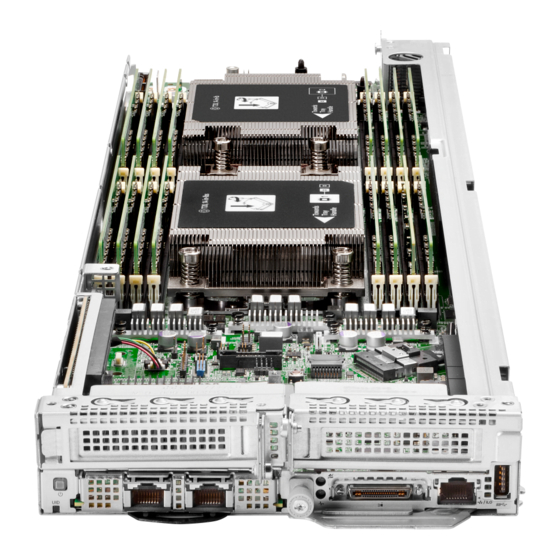
Page 14: Processor And Socket Components
Processor and socket components Item Description Pin field Rail frame Carrier frame Processor Force frame Captive screws (Torx T-20) System maintenance switch descriptions Position Default Function Off = iLO 5 security is enabled. On = iLO 5 security is disabled. Reserved Reserved Reserved... -
Page 15: Riser Board Components
For more information, see Secure Boot. Riser board components The HPE ProLiant XL225n Gen10 Plus Server supports both primary and secondary riser board options. These riser options support the installation of half-height, half-length (low profile) expansion cards. For more information on the type of expansion options supported in each riser, see PCIe expansion option population rules. - Page 16 Item Description Riser interconnect receptacle Pump-cold plate signal connector for processor 2 Pump-cold plate signal connector for processor 1 Storage controller backup power connector Slot 2 PCIe4 x16 (16, 8, 4, 2, 1) This port is not used in this server. This port is not used in this server.
-
Page 17: Pcie4 Slot Description
Direct liquid cooling system The HPE Apollo Direct Liquid Cooling System is a warm water, server-level cooling solution. This system removes heat from high heat components like high wattage processors and DIMMs. The heat removal is done using a safe, environmentally friendly server coolant. -
Page 18: Server-To-Dlc Manifold Interconnect Tube Set
For more information on the Direct Liquid Cooling System setup and operation, see the following guides: • HPE Apollo Direct Liquid Cooling System Site Preparation Guide https://www.hpe.com/support/apollo-dlc-site-gde • HPE Apollo Rack Mount Coolant Distribution Unit User and Maintenance Guide https://www.hpe.com/support/apollo-cdu-umg • HPE Apollo Rack Mount Coolant Distribution Unit (CDU) Monitoring Software Guide https://www.hpe.com/support/apollo-cdu-sw-ug Server-to-DLC manifold interconnect tube set The DLC manifold is connected to the server cooling loop through pairs of interconnect tubes. -
Page 19: Processor Cooling Loop Components
IMPORTANT: The cooling loop is prefilled with server coolant and sealed by drip-free quick connectors. In the unlikely event of a spill or leak of server coolant from the cooling loop, follow the recommended procedure listed in Appendix II: Spill response of the HPE Apollo Rack Mount Coolant Distribution Unit User and Maintenance Guide (https:// www.hpe.com/support/apollo-cdu-umg). - Page 20 Supply loop quick connector (blue) If a pump failure occurs, the event is recorded in the iLO IML and Active Health System Log. For more information on accessing this record, see the iLO user guide on the HPE website (https://www.hpe.com/support/ilo-docs). Component identification...
-
Page 21: Operations
HPE Apollo Platform Manager (HPE APM) HPE Apollo Platform Manager is a rack-level device that can control power caps for all enclosures installed in a rack. Power capping functionality is configured using the APM GUI and the Redfish API-conformant APM RESTful API. - Page 22 HPE iLO is a remote server management processor embedded on the system boards of supported HPE servers and compute modules. HPE iLO enables the monitoring and controlling of servers from remote locations. Use the HPE iLO web interface to configure power capping on supported servers.
-
Page 23: Power Capping Using Hpe Apollo Platform Manager
Support for NVIDIA GPUs only Power capping using HPE Apollo Platform Manager A global power cap can be applied to all enclosures with one HPE Apollo Platform Manager command. Different caps can be applied to user-defined groups using flexible zones within the same rack. -
Page 24: Disconnect The Tube Set
Disconnect the tube set Procedure 1. Power down the server. 2. Push the female connector (jack) to the male connector (plug) for about 1/8 of an inch. 3. Rotate the female connector counter-clockwise until the tube is pushed off the connector by the springs inside. Remove the server CAUTION: To avoid accidentally dropping the server, observe the following: •... -
Page 25: Remove The Node Cover
Procedure 1. Power down the server. 2. Make sure that the server Do not remove LED is off. 3. If installed, disconnect the tube set. 4. Disconnect all peripheral cables from the server. 5. Remove the server: a. Loosen the release lever thumbscrew (callout 1). b. -
Page 26: Remove The Air Baffle
Procedure 1. Power down the server. 2. If installed, disconnect the tube set. 3. Disconnect all peripheral cables from the server. 4. Remove the server. 5. Place the server on a flat, level work surface. 6. Remove the node cover: a. -
Page 27: Remove The Primary Riser
Remove the primary riser CAUTION: To prevent improper cooling and thermal damage, do not operate the server unless either riser blank or riser cage is installed. Prerequisites Before you perform this procedure, make sure that you have the following items available: •... -
Page 28: Remove The Secondary Riser
9. If a cooling loop is installed, remove the quick connector bracket from the riser: a. Remove the retainer bracket screw (callout 1). b. Remove the retainer bracket (callout 2). c. Pull out the quick connector bracket (callout 3). Remove the secondary riser CAUTION: To prevent improper cooling and thermal damage, do not operate the server unless either riser blank or the riser cage is installed. - Page 29 Procedure 1. Power down the server. 2. If installed, disconnect the tube set. 3. Disconnect all peripheral cables from the server. 4. Remove the server. 5. Place the server on a flat, level work surface. 6. Remove the node cover. 7.
-
Page 30: Install The Secondary Riser
Install the secondary riser Prerequisites Before you perform this procedure, make sure that you have a T-10 Torx screwdriver available. Procedure 1. If the onboard SATA cable or a Smart Array controller cable is attached to the riser, do the following: a. -
Page 31: Install The Primary Riser
3. Do one or both of the following: If the onboard SATA cable or a Smart Array controller cable is attached to the riser, connect the cable. • If a cooling loop is installed, connect the pump-cold plate signal cables to the riser. •... - Page 32 2. If an expansion card or its internal cabling was removed, reinstall these components. 3. If a cooling loop was removed, install the quick connector bracket in the riser: a. Insert the quick connector bracket (callout 1). b. Install the retainer bracket (callout 2). c.
-
Page 33: Install The Air Baffle
Install the air baffle Procedure 1. Make sure that the airflow arrow marker on the air baffle points towards the processor socket 1. 2. Align the guides on the air baffle with the pin on the heatsink numbering pointer at one end, and the notch on the server tray at the other end. -
Page 34: Install The Server
Install the server CAUTION: To avoid accidentally dropping the server, observe the following: • Always support the bottom of the server when removing and sliding it into the server bay. • Do not use the release lever as a handle to carry the server. Procedure 1. -
Page 35: Connect The Tube Set
4. Connect all peripheral cables to the server. 5. If removed, connect the tube set. 6. Power up the server. Connect the tube set Procedure 1. Push the female connector (jack) to the male connector (plug). 2. Rotate the female connector clockwise until it is fully engaged. Operations... -
Page 36: Setup
Setup General site planning Before you begin installing the HPE Apollo 2000 Gen10 Plus System, Hewlett Packard Enterprise recommends that you plan and coordinate the installation process with an authorized HPE representative or partner. Proper planning provides a more efficient installation process and leads to greater availability, reliability, and serviceability of the system. -
Page 37: Hpe Installation Service
HPE-supported products from other vendors that are sold by HPE or by HPE authorized resellers. The Installation Service is part of a suite of HPE deployment services that are designed to give users the peace of mind that comes from knowing that their HPE and HPE-supported products have been installed by an HPE specialist. - Page 38 (Optional) Install the server hardware options. For installation instructions, see Hardware options installation. If you are installing the new server in a new chassis, install the rack rails, and then install the chassis into the rack. See the HPE Apollo 2000 Gen10 Plus System Rack Rail Kit Installation Instructions: https://www.hpe.com/support/apollo2000gen10plus-rackrail Install the server Remove the server blank.
- Page 39 To configure the server to boot from a SAN, see the following guide: https://www.hpe.com/info/boot-from-san-config-guide • If an HPE Smart Array controller is installed, use the HPE Smart Storage Administrator to create arrays: a. From the boot screen, press F10 to run Intelligent Provisioning. b. From Intelligent Provisioning, run HPE Smart Storage Administrator.
-
Page 40: Operational Requirements
For multiple server OS deployments in a cluster, use HPE Performance Cluster Manager. • b. Using the SPP, update the system drivers. Register the server 13. To experience quicker service and more efficient support, register the server at the HPE website: https://myenterpriselicense.hpe.com Operational requirements Site requirements The server must be located in a computer room or server room. -
Page 41: Temperature Requirements
CAUTION: If a third-party rack is used, observe the following additional requirements to ensure adequate airflow and to prevent damage to the equipment: • Front and rear doors—If the 42U rack includes closing front and rear doors, you must allow 5,350 sq cm (830 sq in) of holes evenly distributed from top to bottom to permit adequate airflow (equivalent to the required 64 percent open area for ventilation). -
Page 42: Server Warnings And Cautions
• Install a drive or drive blank into all drive bays. • Install a server or a blank into all server bays. • Install a power supply or power supply blank into all power supply bays. Server warnings and cautions WARNING: To reduce the risk of personal injury, electric shock, or damage to the equipment, disconnect the power cord to remove power from the server. -
Page 43: Electrostatic Discharge
CAUTION: When performing non-hot-plug operations, you must power down the server and/or the system. However, it may be necessary to leave the server powered up when performing other operations, such as hot-plug installations or troubleshooting. CAUTION: Do not operate the server for long periods with the access panel open or removed. Operating the server in this manner results in improper airflow and improper cooling that can lead to thermal damage. -
Page 44: Hardware Options Installation
Hardware options installation Hardware option installation guidelines WARNING: To reduce the risk of personal injury from hot surfaces, allow the drives and the internal system components to cool before touching them. CAUTION: To prevent damage to electrical components, properly ground the server before beginning any installation procedure. -
Page 45: Using The Suv Cable In A Kvm Setup
Connect a client system using a supported USB to Ethernet adapter and access the iLO web interface, remote console, CLI, and iLO RESTful API. For more information, see the iLO user guide on the HPE website (https:// www.hpe.com/support/ilo-docs). VGA port Connect an analog display device. -
Page 46: Transceiver Option
4. Connect a USB mouse to the USB hub. 5. Connect a USB keyboard to the USB hub. 6. Connect a USB key or a USB optical drive to the USB hub. Transceiver option Transceiver warnings and cautions WARNING: Fiber-optic transceivers and fiber-optic cables connected to transceivers emit laser light that can damage your eyes. -
Page 47: Pcie Riser Options
• Make sure that a compatible network adapter is installed in the node. Determine if installing the transceiver in the network adapter requires a specific system operating temperature. For more information, see the HPE website (https:// www.hpe.com/support/xl225ngen10plus-thermal). • Review the following: ◦... -
Page 48: Installing The Primary Riser Board
Riser option Slot number PCIe Physical connector link Signal source technology width P2 secondary riser (P20264-B21) PCIe 3.0 Processor 2 P1 secondary riser for direct attach PCIe 4.0 PCIe signal: Processor 1 NVMe SSD (P22337-B21) NVMe signal: Processor 2 This riser is supported only in dual-processor configurations. One riser supports up to two NVMe SSDs per node. These risers support the installation of half–height, half–length (low–profile) expansion cards. - Page 49 Install the primary riser board: a. Attach the riser board to the cage (callout 1). b. Install riser board screws (callout 2). If you are planning to install an expansion card in this riser, install it now. 10. Install the primary riser: a.
-
Page 50: Installing The Secondary Riser Board
The installation is complete. Installing the secondary riser board Prerequisites Before you perform this procedure, make sure that you have the following items available: • T-10 Torx screwdriver • T-15 Torx screwdriver Procedure Power down the server. Disconnect all peripheral cables from the server. Remove the server. - Page 51 Remove the interconnect receptacle bracket. If you are installing the onboard SATA cable or a Smart Array type-p controller cable, attach the controller cable to the riser board: a. Connect the controller cable to the SlimSAS port. b. Secure the controller cable with the clip. 10.
- Page 52 c. Install the riser board screws. 11. Install the interconnect receptacle bracket: a. Use the spools to position the interconnect receptacle bracket. Hardware options installation...
- Page 53 b. Install the interconnect receptacle bracket screws. 12. If the onboard SATA cable or a Smart Array controller cable is attached to the riser, do the following: a. Route the cable underneath the riser cutout (callout 1). b. To ensure that the cable is not caught underneath the riser during the installation, position the cable away from the riser connector (callout 2).
-
Page 54: Storage Controller Cable Options
• Expansion card • Smart Array type-p controller 14. Install the secondary riser: a. Align the spools on the riser with the notches on the server tray (callout 1). b. Carefully press the riser down on its system board connector (callout 2). Make sure that the riser board is firmly seated. - Page 55 • T-10 Torx screwdriver • T-15 Torx screwdriver Procedure Power down the server. If installed, disconnect the tube set. Disconnect all peripheral cables from the server. Remove the server. Place the server on a flat, level work surface. Remove the node cover. If installed, remove the air baffle.
- Page 56 10. Remove the interconnect receptacle bracket. 11. Remove the riser board screws. Hardware options installation...
- Page 57 12. Remove the riser board: a. To release the board from the bracket spools, slide the board towards the direction of the interconnect receptacle. b. Separate the board from the bracket. 13. Attach the controller cable to the riser board: a.
- Page 58 15. Install the riser board screws. 16. Install the interconnect receptacle bracket: a. Use the spools to position the bracket over the interconnect receptacle. Hardware options installation...
- Page 59 b. Install the receptacle bracket screws. 17. If removed, install the expansion card in the secondary riser. 18. Install the secondary riser. 19. Do one of the following: Connect the controller cable to the onboard SATA controller port. • Connect the controller cable to the Smart Array type-p controller ports. •...
-
Page 60: Storage Controller Options
The installation is complete. Storage controller options To support SAS and SATA drives, install an HPE Smart Array type-p controller in the secondary riser. Use the HPE Smart Storage Administrator (SSA) to manage the controller functions from a single, intuitive interface. - Page 61 Disconnect all peripheral cables from the server. Remove the server. Place the server on a flat, level work surface. Remove the node cover. If installed, remove the air baffle. Remove the secondary riser. If the Smart Array controller SAS cable is not yet connected to the secondary riser board, install it now. 10.
- Page 62 12. Install the low-profile bracket on the expansion card. 13. Install the storage controller: a. Insert the board connector in the riser slot (callout 1). Make sure that the board is seated firmly in the slot. b. Install the bracket screw (callout 2). Hardware options installation...
-
Page 63: Configuring An Hpe Smart Array Gen10 Controller
19. Connect all peripheral cables to the server. 20. If removed, connect the tube set. 21. Power up the server. 22. Configure the HPE Smart Array Gen10 controller. The installation is complete. Configuring an HPE Smart Array Gen10 controller Procedure 1. -
Page 64: Expansion Card Options
• SPP – See the product documentation in the information library: https://www.hpe.com/info/spp/docs • UEFI System Utilities or HPE Smart Storage Administrator – See the HPE Smart Array SR Gen10 Configuration Guide in the information library: https://www.hpe.com/info/smartstorage-docs Expansion card options The server supports PCIe riser options for installing half‑height, half‑length (low‑profile) expansion cards. The following expansion options are supported in this server: •... - Page 65 ◦ T-10 Torx screwdriver ◦ T-15 Torx screwdriver Procedure Power down the server. If installed, disconnect the tube set. Disconnect all peripheral cables from the server. Remove the server. Place the server on a flat, level work surface. Remove the node cover. Remove the primary riser.
- Page 66 11. Make sure that any switches or jumpers on the expansion card are set properly. For more information, see the documentation that ships with the option. 12. Install the expansion card: a. Insert the card connector in the riser slot (callout 1). Make sure that the card is seated firmly in the slot.
-
Page 67: Installing An Expansion Card In The Secondary Riser
Installing an expansion card in the secondary riser IMPORTANT: The 8 GT/s transfer rate in PCIe Gen3 is doubled in PCIe Gen4 to 16 GT/s. However, PCIe Gen4 devices installed in the P2 secondary riser slot will only operate in PCIe Gen3 speed. Prerequisites Observe the PCIe expansion option population rules. - Page 68 11. If installed, remove the full-height bracket from the expansion card. 12. Install the low-profile bracket on the expansion card. Hardware options installation...
- Page 69 13. Make sure that any switches or jumpers on the expansion card are set properly. For more information, see the documentation that ships with the option. 14. Install the expansion card: a. Insert the card connector in the riser slot (callout 1). Make sure that the card is seated firmly in the slot.
-
Page 70: Ocp Nic 3.0 Adapter Option
19. Install the server. 20. Connect all peripheral cables to the server. 21. If removed, connect the tube set. 22. Power up the server. The installation is complete. OCP NIC 3.0 adapter option The server supports SFF dual-port and quad-port OCP NIC 3.0 adapter options with various interfaces and advanced interconnect features for high-bandwidth applications. -
Page 71: Processor And Heatsink Options
a. Rotate the locking pin to the open (vertical) position (callout 1). b. Slide the OCP 3.0 NIC adapter into the bay until it clicks into place (callout 2). Make sure that the card is seated firmly in the slot. c. -
Page 72: Installing The Processor And Heatsink Options
Installing the processor and heatsink options Procedure 1. Determine if the new processor requires a specific system operating temperature. For more information, see the HPE website (https://www.hpe.com/support/xl225ngen10plus-thermal). 2. Identify the processor and socket components. 3. Review the processor cautions. 4. Install the processor. - Page 73 Use a T-20 Torx screwdriver to loosen the three captive screws in the sequence shown in the following image, and then pivot the force frame upward. Remove the external cap: a. Hold the lift tabs near the front end of the rail frame, and then pivot the rail frame to the vertical position. b.
- Page 74 Install the processor: a. Hold the processor by its carrier handle and slide the processor into the rail frame until it engages with a click sound. b. Remove the pin field cover cap. CAUTION: To prevent the risk of damaging the pins in the processor socket, do not reinstall the pin field cover cap after removing it.
-
Page 75: Installing A Heatsink
a. Pivot the spring loaded force frame downward and hold it down (callout 1). b. Use a T-20 Torx screwdriver to tighten the captive screws in the sequence shown in the following image (callouts 2– When using a torque wrench to tighten the screws, apply a torque of 1.58 N⋅m (14 lbf-in). 11. -
Page 76: Memory Options
The installation is complete. Memory options The server has 16 DIMM slots—8 memory channels per processor—supporting HPE DDR4 SmartMemory (RDIMM or LRDIMM). At least one DIMM per processor is required for system operation. The installed processor determines the maximum memory capacity per server. For more information, see the QuickSpecs on the product page (https://www.hpe.com/servers/apollo2000). -
Page 77: Dimm Population Information
For specific DIMM population information, see the DIMM population guidelines on the Hewlett Packard Enterprise website (https://www.hpe.com/docs/amd-population-rules-Gen10Plus). HPE SmartMemory speed information For more information about memory speed information in HPE servers using AMD EPYC processors, see the Hewlett Packard Enterprise website (https://www.hpe.com/docs/amd-speed-table-Gen10Plus). Installing a DIMM Procedure Power down the server. - Page 78 • In a DLC configuration with the DIMM-processor cooling loop, remove the following: ◦ DIMM release tool ◦ DIMM cover for the slot where the new DIMM will be installed Hardware options installation...
- Page 79 Install the DIMM: a. Open the DIMM slot latches. In a DLC configuration with the DIMM-processor cooling loop, use the longer end of the DIMM release tool to open the DIMM slot latches. b. Align the notch on the bottom edge of the DIMM with the keyed surface of the DIMM slot, and then fully press the DIMM into the slot until the latches snap back into place.
- Page 80 The DIMM slots are structured to ensure proper installation. If you try to insert a DIMM but it does not fit easily into the slot, you might have positioned it incorrectly. Reverse the orientation of the DIMM and insert it again. Do one of the following: •...
- Page 81 ◦ DIMM release tool 10. Install the node cover. 11. Install the server. 12. Connect all peripheral cables to the server. 13. If removed, connect the tube set. 14. Power up the server. The installation is complete. After installing the DIMMs, use the System Utilities > System Configuration > BIOS/Platform Configuration (RBSU) > Memory Options to configure the memory settings.
-
Page 82: Mezzanine Card Option
Mezzanine card option The server supports a mezzanine card to install an internal USB device that can be used as a flash boot media or for data backup/redundancy. Installing the mezzanine card for internal USB device Procedure Power down the server. If installed, disconnect the tube set. -
Page 83: Hpe Trusted Platform Module 2.0 Gen10 Plus Option
HPE Trusted Platform Module 2.0 Gen10 Plus option Overview Use these instructions to install and enable an HPE TPM 2.0 Gen10 Plus Kit in a supported server. This option is not supported on Gen10 and earlier servers. This procedure includes three sections: 1. -
Page 84: Hpe Trusted Platform Module 2.0 Guidelines
Hewlett Packard Enterprise is not liable for blocked data access caused by improper TPM use. For operating instructions, see the TPM documentation or the encryption technology feature documentation provided by the operating system. Installing and enabling the HPE TPM 2.0 Gen10 Plus option Installing the Trusted Platform Module board... - Page 85 Update the system ROM. Locate and download the latest ROM version from the Hewlett Packard Enterprise Support Center website (https:// www.hpe.com/support/hpesc). To update the system ROM, follow the instructions on the website. Power down the server. If installed, disconnect the tube set.
- Page 86 3. Install the TPM cover: a. Align the pins on the cover with the openings on the system board. b. Press straight down on the middle of the cover until the alignment pins are seated into the holes. 4. Secure the rivets into place by pushing them firmly through the holes in the TPM cover. Hardware options installation...
- Page 87 5. Proceed to "Preparing the server for operation." Preparing the server for operation Procedure 1. If the primary riser was removed, install the riser. 2. Install the node cover. 3. Install the server. 4. Connect all peripheral cables to the server. 5.
- Page 88 • "Current TPM Type" is set to TPM 2.0. • "Current TPM State" is set to Present and Enabled. "TPM Visibility" is set to Visible. • 4. If changes were made in the previous step, press the F10 key to save your selection. 5.
- Page 89 For more information, see the Microsoft website. Retaining the BitLocker recovery key/password The recovery key/password is generated during BitLocker setup, and can be saved and printed after BitLocker is enabled. When using BitLocker, always retain the recovery key/password. The recovery key/password is required to enter Recovery Mode after BitLocker detects a possible compromise of system integrity.
-
Page 90: Cabling
Cabling Cabling guidelines The cable colors in the cabling diagrams used in this chapter are for illustration purposes only. Most of the system cables are black. Observe the following guidelines when working with system cables. Before connecting cables • Note the port labels on the PCA components. Not all of these components are used by all systems: ◦... -
Page 91: Node Power Button Cabling
• Remove cables that are no longer being used. Retaining them inside the system can restrict airflow. If you intend to use the removed cables later, label and store them for future use. Node power button cabling Storage cabling Cabling... -
Page 92: Onboard Sata Controller Cabling
Onboard SATA controller cabling HPE Smart Array type-p controller cabling Cabling... -
Page 93: Storage Controller Backup Power Cabling
Storage controller backup power cabling Pump-cold plate signal cabling Pump-cold plate signal cabling: Processor cooling loop Item Description Orange Pump-cold plate signal cable for processor 1 Blue Pump-cold plate signal cable for processor 2 Pump-cold plate signal cabling: DIMM-processor cooling loop Cabling... - Page 94 Item Description Orange Pump-cold plate signal cable for processor 1 Blue Pump-cold plate signal cable for processor 2 Cabling...
-
Page 95: Software And Configuration Utilities
Product QuickSpecs For more information about product features, specifications, options, configurations, and compatibility, see the product QuickSpecs on the Hewlett Packard Enterprise website (https://www.hpe.com/info/qs). Active Health System Viewer Active Health System Viewer (AHSV) is an online tool used to read, diagnose, and resolve server issues quickly using AHS uploaded data. -
Page 96: Hpe Ilo 5
HPE iLO 5 iLO 5 is a remote server management processor embedded on the system boards of supported HPE servers and compute modules. iLO enables the monitoring and controlling of servers from remote locations. iLO management is a powerful tool that provides multiple ways to configure, update, monitor, and repair servers remotely. -
Page 97: Ilo Service Port
You cannot access the server by connecting to the Service Port. • You cannot access the connected device from the server. For more information about the iLO Service Port, see the iLO user guide at the following website: https://www.hpe.com/ support/ilo-docs. Software and configuration utilities... -
Page 98: Ilo Restful Api
RESTful Interface Tool The RESTful Interface Tool (iLOREST) is a scripting tool that allows you to automate HPE server management tasks. It provides a set of simplified commands that take advantage of the iLO RESTful API. You can install the tool on your computer for remote use or install it locally on a server with a Windows or Linux Operating System. -
Page 99: Management Security
Provisioning without rebooting your server. Management security HPE ProLiant Gen10, HPE ProLiant Gen10 Plus, and HPE Apollo servers are built with some of the industry's most advanced security capabilities, out of the box, with a foundation of secure embedded management applications and firmware. The management security provided by HPE embedded management products enables secure support of modern workloads, protecting your components from unauthorized access and unapproved use. -
Page 100: Hpe Performance Cluster Manager
HPE Cray Programming Environment (CPE) provides a complete software development environment, including HPC optimization tools. It is an HPE supported toolchain for AMD, Intel, and ARM systems. For more information, see the HPE Cray Programming Environment (CPE) documentation website (https://www.hpe.com/support/apollo2000gen10plus). -
Page 101: Secure Boot
Operating systems must support Secure Boot and have an EFI boot loader signed with one of the authorized keys to boot. For more information about supported operating systems, see https://www.hpe.com/servers/ossupport. You can customize the certificates embedded in the UEFI BIOS by adding or removing your own certificates, either from a management console directly attached to the server, or by remotely connecting to the server using the iLO Remote Console. -
Page 102: Launching The Embedded Uefi Shell
HPE Smart Storage Administrator HPE SSA is the main tool for configuring arrays on HPE Smart Array SR controllers. It exists in three interface formats: the HPE SSA GUI, the HPE SSA CLI, and HPE SSA Scripting. All formats provide support for configuration tasks. Some of the advanced tasks are available in only one format. -
Page 103: Hpe Infosight For Servers
For more information, see HPE Smart Array SR Gen10 Configuration Guide at the Hewlett Packard Enterprise website. HPE InfoSight for servers The HPE InfoSight portal is a secure web interface hosted by HPE that allows you to monitor supported devices through a graphical interface. -
Page 104: Keeping The System Current
The SPP is also available for download from the SPP download page at https://www.hpe.com/servers/spp/download. Smart Update Manager SUM is an innovative tool for maintaining and updating the firmware, drivers, and system software of HPE ProLiant, HPE BladeSystem, HPE Synergy, HPE Superdome Flex servers, and HPE Apollo servers, infrastructure, and associated options. - Page 105 Integrated Smart Update Tools (SUT) is the smart update solution for performing online firmware and driver updates. SUT is used with iLO 4, iLO 5, and with update solutions (management appliances such as iLO Amplifier Pack or HPE OneView and Smart Update Manager (SUM) to stage, install, and activate firmware and driver updates.
-
Page 106: Drivers
Procedure 1. Access the System ROM Flash Binary component for your server from the Hewlett Packard Enterprise Support Center (https://www.hpe.com/support/hpesc). 2. Copy the binary file to a USB media or iLO virtual media. 3. Attach the media to the server. -
Page 107: Operating System Version Support
For information about specific versions of a supported operating system, refer to the operating system support matrix. HPE Pointnext Portfolio HPE Pointnext delivers confidence, reduces risk, and helps customers realize agility and stability. Hewlett Packard Enterprise helps customers succeed through Hybrid IT by simplifying and enriching the on-premise experience, informed by public cloud qualities and attributes. -
Page 108: Troubleshooting
• Error Message Guide for HPE ProLiant Gen10 servers and HPE Synergy provides a list of error messages and information to assist with interpreting and resolving error messages. •... -
Page 109: Safety, Warranty, And Regulatory Information
To view the regulatory information for your product, view the Safety and Compliance Information for Server, Storage, Power, Networking, and Rack Products, available at the Hewlett Packard Enterprise Support Center: https://www.hpe.com/support/Safety-Compliance-EnterpriseProducts Additional regulatory information Hewlett Packard Enterprise is committed to providing our customers with information about the chemical substances in our products as needed to comply with legal requirements such as REACH (Regulation EC No 1907/2006 of the European Parliament and the Council). -
Page 110: Turkey Rohs Material Content Declaration
Фараби даңғ ылы, 77/7, Телефон/факс: +7 727 355 35 50 Manufacturing date: The manufacturing date is defined by the serial number. If you need help identifying the manufacturing date, contact tre@hpe.com. Turkey RoHS material content declaration Türkiye Cumhuriyeti: AEEE Yönetmeliğine Uygundur... -
Page 111: System Battery Replacement
System battery replacement Removing and replacing the system battery WARNING: The server contains an internal lithium manganese dioxide, a vanadium pentoxide, or an alkaline battery that provides power to the real-time clock. If this battery is not properly handled, a risk of the fire and burns exists. To reduce the risk of personal injury: •... - Page 112 Slightly push the metal tab, and then install the new system battery in the socket. 10. Install the node cover. 11. Install the server. 12. Connect all peripheral cables to the server. 13. If removed, connect the tube set. 14. Power up the server. Properly dispose of the old battery.
-
Page 113: Specifications
The maximum system operating temperature for most components installed in the system is 35°C (95°F). However, some components in specific configurations are subject to temperature limitations. To ensure safe and reliable system operation, observe the limited operating temperature for these configurations. For more information, see the HPE website: https://www.hpe.com/support/xl225ngen10plus-thermal... -
Page 114: Websites
Storage white papers and analyst reports https://www.hpe.com/storage/whitepapers For additional websites, see Support and other resources. Product websites HPE ProLiant XL225n Gen10 Plus Server product page https://www.hpe.com/servers/apollo2000 HPE ProLiant XL225n Gen10 Plus Server support page https://www.hpe.com/support/apollo2000gen10plus HPE ProLiant XL225n Gen10 Plus Server user documents https://www.hpe.com/info/apollo2000gen10plus-docs... -
Page 115: Support And Other Resources
• To download product updates: Hewlett Packard Enterprise Support Center https://www.hpe.com/support/hpesc Hewlett Packard Enterprise Support Center: Software downloads https://www.hpe.com/support/downloads My HPE Software Center https://www.hpe.com/software/hpesoftwarecenter • To subscribe to eNewsletters and alerts: https://www.hpe.com/support/e-updates • To view and update your entitlements, and to link your contracts and warranties with your profile, go to the Hewlett Packard Enterprise Support Center More Information on Access to Support Materials page: https://www.hpe.com/support/AccessToSupportMaterials... -
Page 116: Remote Support
IMPORTANT: Access to some updates might require product entitlement when accessed through the Hewlett Packard Enterprise Support Center. You must have an HPE Passport set up with relevant entitlements. Remote support Remote support is available with supported devices as part of your warranty or contractual support agreement. It provides intelligent event diagnosis, and automatic, secure submission of hardware event notifications to Hewlett Packard Enterprise, which will initiate a fast and accurate resolution based on your product's service level.
Need help?
Do you have a question about the ProLiant XL225n Gen10 Plus and is the answer not in the manual?
Questions and answers