Table of Contents
Advertisement
Quick Links
HPE ProLiant XL645d Gen10 Plus Server User Guide
Abstract
This document is for the person who installs, administers, and troubleshoots servers and storage systems. Hewlett
Packard Enterprise assumes you are qualified in the servicing of computer equipment and trained in recognizing hazards
in products with hazardous energy levels.
Part Number: P39411-001
Published: February 2021
Edition: 1
Advertisement
Table of Contents

Related Manuals for HPE ProLiant XL645d


Summary of Contents for HPE ProLiant XL645d
- Page 1 HPE ProLiant XL645d Gen10 Plus Server User Guide Abstract This document is for the person who installs, administers, and troubleshoots servers and storage systems. Hewlett Packard Enterprise assumes you are qualified in the servicing of computer equipment and trained in recognizing hazards in products with hazardous energy levels.
- Page 2 © Copyright 2021 Hewlett Packard Enterprise Development LP Notices The information contained herein is subject to change without notice. The only warranties for Hewlett Packard Enterprise products and services are set forth in the express warranty statements accompanying such products and services. Nothing herein should be construed as constituting an additional warranty.
-
Page 3: Table Of Contents
Supported drives......................................22 HPE Smart Drive......................................22 Drive bay numbering........................................24 Storage controller components....................................24 NVMe adapter components....................................25 HPE NS204i-t Gen10 Plus NVMe Boot Controller components.......................25 Operations........................26 Power up the server........................................26 Power down the server......................................26 Extend the chassis from the rack..................................26 Open the chassis front door.................................... - Page 4 Installing an HPE Smart Storage Battery............................79 HPE Trusted Platform Module 2.0 Gen10 Plus option..........................81 Overview...........................................81 HPE Trusted Platform Module 2.0 guidelines........................... 82 Installing and enabling the HPE TPM 2.0 Gen10 Plus option..................82 Cabling..........................88 Cabling guidelines........................................88 Front I/O cabling........................................... 89...
- Page 5 Drive-controller-backplane configuration cabling.............................91 Gen10 Plus 8 SFF SAS/SATA Standard backplane cabling....................91 SAS/SATA-NVMe configuration cabling............................92 HPE NS204i-t Gen10 Plus NVMe Boot Controller-M.2 SSD module cabling............95 HPE Smart Storage Battery cabling ................................. 96 Power switch cabling........................................96 Drive backplane power cabling.....................................96 Gen10 Plus 8 SFF SAS/SATA Standard backplane power cabling................97...
- Page 6 Server mechanical specifications..................................115 Power supply specifications....................................115 HPE 3000 W 200–277 VAC Platinum Hot-plug Power Supply...................115 HPE 54 V Out 3000 W 200–277 VAC Hot-plug Power Supply.................. 116 Websites......................... 117 Support and other resources..................118 Accessing Hewlett Packard Enterprise Support............................. 118 Accessing updates........................................
-
Page 7: Component Identification
Component identification This chapter describes the external and internal server features and components. Front panel components Item Description Serial number/iLO information pull tab Power switch module Drive box 1 (labeled Node 2) chassis front door lever button Drive box 2 (labeled Node 1) Front panel LEDs and buttons Component identification... -
Page 8: Uid Button Functionality
The UID button can be used to display the Server Health Summary when the server will not power on. For more information, see the latest HPE iLO 5 User Guide on the Hewlett Packard Enterprise website. Front panel LED power fault codes The following table provides a list of power fault codes, and the subsystems that are affected. -
Page 9: Front Panel Pass-Thru Board Components
Subsystem LED behavior FlexibleLOM 5 flashes Storage controllers 6 flashes System board PCIe slots 7 flashes Power backplane or storage backplane 8 flashes Power supply 9 flashes Front panel pass-thru board components Item Description Front I/O cable connector Drive cable connectors 1 to 4 Drive backplane power cable connector Drive SAS/SATA cable connector Front panel pass-thru board 1 (Node 1 drive I/O) -
Page 10: Rear Panel Components
Rear panel components SXM GPU configuration Item Description SXM GPU trays 12 V power supplies (2) 54V power supplies (4) APM 2.0 connector USB 3.1 Gen 1 Type-A port NIC/shared iLO network port Slot 10 PCIe4 x16 (16, 8, 4, 2, 1) SUV port Slot 9 PCIe4 x16 (16, 8, 4, 2, 1) OCP 3.0 NIC adapter slot blank... -
Page 11: Rear Panel Leds And Buttons
PCIe GPU configuration Item Description PCIe GPU trays 12 V power supplies (4) APM 2.0 connector USB 3.1 Gen 1 Type-A port NIC/shared iLO network port Slot 10 PCIe4 x16 (16, 8, 4, 2, 1) SUV port Slot 9 PCIe4 x16 (16, 8, 4, 2, 1) OCP 3.0 NIC adapter slot blank Serial number/iLO information pull tab Rear panel LEDs and buttons... -
Page 12: System Board Module Components
Item Description Definition Power On/Standby button and Solid green = System on Flashing green = Performing power-on sequence Solid amber = System in standby Off = No power present UID LED Solid blue = Activated Flashing blue: • 1 flash per second = Remote management or firmware upgrade in progress •... -
Page 13: System Board Components
System board components Item Description HPE NS204i-t Gen10 Plus NVMe Boot Controller connector System battery TPM connector Secondary PCIe4 x16 riser connector 5 Secondary PCIe4 x16 riser connector 4 Processor x8 Slim SAS NVMe/SATA 6GB/s port Secondary PCIe4 x16 riser connector 3... - Page 14 System maintenance switch descriptions Position Default Function Off = iLO 5 security is enabled. On = iLO 5 security is disabled. Reserved Reserved Reserved Off = Power-on password is enabled. On = Power-on password is disabled. 1, 2, 3 Off = No function On = Restore default manufacturing settings Reserved —...
- Page 15 DIMM label identification To determine DIMM characteristics, see the label attached to the DIMM. The information in this section helps you to use the label to locate specific information about the DIMM. Component identification...
- Page 16 AA = CAS 26-22-22 (for 3DS LRDIMM) DIMM type R = RDIMM (registered) L = LRDIMM (load reduced) For more information about product features, specifications, options, configurations, and compatibility, see the HPE DDR4 SmartMemory QuickSpecs on the Hewlett Packard Enterprise website (https://www.hpe.com/support/ DDR4SmartMemoryQS). Component identification...
-
Page 17: Midplane Interposer Ports
Processor and socket components Item Description Pin field Rail frame Carrier frame Processor Force frame Captive screws (Torx T-20) Midplane interposer ports Component identification... -
Page 18: Sxm4 Gpu Slots
Item Description Port 1 Port 2 SXM4 GPU slots Item Description SXM GPU slots 1 and 2 SXM GPU slots 3 and 4 PCIe GPU tray components Double-wide PCIe GPUs can be installed in slots 1, 3, 5, and 7; and single-wide GPUs can be installed in slots 1-8. You can install either 4 double-wide PCIe GPUs or 8 single-wide PCIe GPUs in a PCIe GPU tray. - Page 19 8 single-width GPU configuration Item Description PCIe single-width GPU slots 1-8 4 double-width GPU configuration Item Description PCIe double-width GPU slots 1, 3, 5, and 7 Component identification...
-
Page 20: Riser Board Components
A system board module supports primary, secondary, and tertiary riser board options. The primary and secondary riser options support the installation of half-height, half-length (low profile) PCIe cards. The tertiary riser board contains the HPE Smart Storage Battery connector. Primary riser board components... -
Page 21: Power Supply Led
Item Description x8 Slim SAS NVMe/SATA 6GB/s port Pump-cold plate signal connector for processor Storage controller backup power connector Slot 10 PCIe4 ×16 (16, 8, 4, 2, 1) Slim SAS x4 port for front panel LEDs Power supply LED Status Description Solid green Power supply is on and is operating normally. -
Page 22: Drives
8 SFF Gen10 SAS/SATA drive backplane supports 6Gbps SATA/12Gbps SAS drives • 8 SFF U.3 Premium drive backplane supports x2NVMe drives and x4NVMe drives HPE Smart Drive This HPE Smart Drive carrier supports SAS, SATA, and NVMe drives. Drive LEDs Component identification... - Page 23 Item Description Status Locate • Solid blue = The drive is being identified by a host application. • Flashing blue = The drive carrier firmware is being updated or requires an update. Activity ring • Rotating green = Drive activity. •...
-
Page 24: Drive Bay Numbering
Storage controller components For component and LED identification, see the user guide for your storage controller series on the Hewlett Packard Enterprise website (https://www.hpe.com/info/smartstorage-docs). For a complete list of supported storage controller models, see the server QuickSpecs on the Hewlett Packard Enterprise website (https://www.hpe.com/info/qs). -
Page 25: Nvme Adapter Components
NVMe adapter components Item Description Port 1 Port 2 HPE NS204i-t Gen10 Plus NVMe Boot Controller components Item Description Drive retaining screws Thumbscrew Thermal interface pad Drive bay 1 Drive bay 2 Component identification... -
Page 26: Operations
Operations Power up the server To power up the server, use one of the following methods: • Press the Power On/Standby button. • Use the virtual power button through iLO. Power down the server Before powering down the server for any upgrade or maintenance procedures, perform a backup of critical server data and programs. -
Page 27: Open The Chassis Front Door
Open the chassis front door CAUTION: For proper cooling, do not exceed two minutes with the chassis front door open. Exceeding two minutes can lead to thermal damage or system shutdown. Procedure Open the chassis front door. Close the chassis front door CAUTION: For proper cooling, do not exceed two minutes with the chassis front door open. -
Page 28: Remove The Midplane Panel
Procedure Close the chassis front door. Remove the midplane panel Procedure 1. Back up all server data. 2. . 3. Extend the chassis from the rack. 4. Remove the midplane panel. Operations... -
Page 29: Remove The Enclosure Midplane
Remove the enclosure midplane Procedure 1. Power down the server. 2. Extend the chassis from the rack. 3. Disconnect all peripheral cables from the server. 4. Remove the system board module from the chassis. 5. Remove the GPU tray. 6. Remove the power supplies. 7. -
Page 30: Remove The Gpu Tray From The Chassis
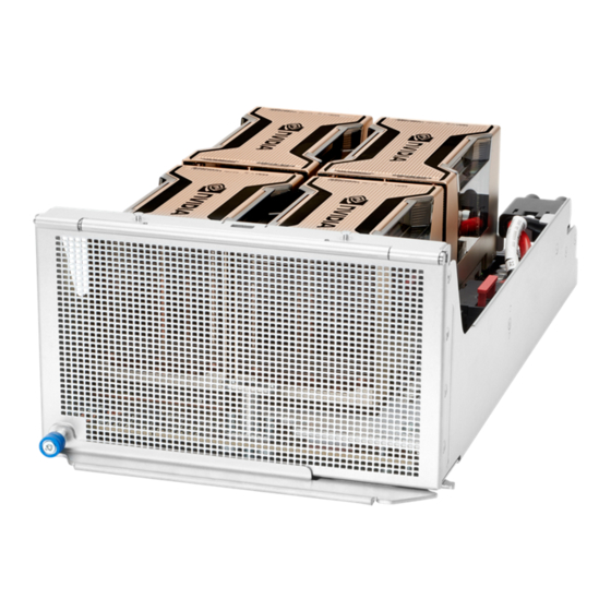
More information Remove the midplane panel Remove the GPU tray from the chassis Procedure 1. Back up all server data. 2. Power down the server. 3. Remove the GPU tray from the chassis. The right GPU tray is shown in the image. The steps for removing the left GPU tray are the same. Depending on the chassis configuration, your GPU tray might look different. -
Page 31: Remove The System Board Module From The Chassis
Remove the system board module from the chassis Procedure 1. Back up all server data. 2. Power down the server. 3. Disconnect all peripheral cables from the server. 4. Remove the system board module from the chassis. The image shows removing a right system board module. The steps for removing the left system board module are the same. -
Page 32: Remove The System Board Module Access Panel
Remove the system board module access panel WARNING: To reduce the risk of personal injury from hot surfaces, allow the drives and the internal system components to cool before touching them. CAUTION: To prevent damage to electrical components, take the appropriate anti-static precautions before beginning any installation, removal, or replacement procedure. -
Page 33: Install The System Board Module Access Panel
More information Remove the system board module from the chassis Install the system board module access panel WARNING: To reduce the risk of personal injury from hot surfaces, allow the drives and the internal system components to cool before touching them. CAUTION: To prevent damage to electrical components, take the appropriate anti-static precautions before beginning any installation, removal, or replacement procedure. -
Page 34: Install The Air Baffle
3. Disconnect all peripheral cables from the server. 4. Remove the system board module from the chassis. 5. Place the system board module on a flat, level work surface. 6. Remove the system board module access panel. 7. Remove the air baffle. Install the air baffle Procedure Install the air baffle. -
Page 35: Install The Midplane Interposer
6. Remove the system board module access panel. 7. Remove the midplane interposer. 8. Remove any cables connected to the interposer. More information Remove the system board module from the chassis Remove the system board module access panel Install the midplane interposer Procedure Install the midplane interposer. -
Page 36: Remove A Pcie Riser
Remove a PCIe riser Prerequisites Before you perform this procedure, make sure that you have a T-10 Torx screwdriver available. Procedure 1. Back up all server data. 2. Power down the server. 3. Disconnect all peripheral cables from the server. 4. - Page 37 • Secondary riser • Tertiary riser Operations...
- Page 38 More information Remove the system board module from the chassis Remove the system board module access panel Remove the midplane interposer Operations...
-
Page 39: Setup
HPE support services offer upgraded service levels to expand the standard product warranty with easy-to-buy, easy-to- use support packages that will help you make the most of your server investments. Some of the HPE support services for hardware, software or both are: •... -
Page 40: Setting Up The Server
Installation Service is part of a suite of HPE deployment services that are designed to give users the peace of mind that comes from knowing that their HPE and HPE-supported products have been installed by an HPE specialist. The HPE Installation Service provides the following benefits: •... - Page 41 Network adapters • Intelligent Provisioning To set up storage, do one of the following: To configure the server to boot from a SAN, see the HPE Boot from SAN Configuration Guide guide at https:// • www.hpe.com/info/boot-from-san-config-guide. • If an SR controller is installed, use HPE Smart Storage Administrator to create arrays: a.
- Page 42 Enable SW RAID. d. Save the configuration and reboot the server. e. Create an array using either the UEFI System Utilities or HPE Smart Storage Administrator. To use the UEFI System Utilities: From the boot screen, press F9 to run UEFI System Utilities.
- Page 43 • Be only accessible to authorized technicians trained the room restriction reasons and precautions. • Be within an area that is ideally locked or at minimum not accessible to unauthorized personnel. Space and airflow requirements To allow for servicing and adequate airflow, observe the following space and airflow requirements when deciding where to install a rack: •...
- Page 44 CAUTION: To reduce the risk of damage to the equipment when installing third-party options: • Do not permit optional equipment to impede airflow around the server or to increase the internal rack temperature beyond the maximum allowable limits. • Do not exceed the manufacturer’s TMRA. Power requirements Installation of this equipment must comply with local and regional electrical regulations governing the installation of IT equipment by licensed electricians.
- Page 45 For important safety, environmental, and regulatory information, see Safety and Compliance Information for Server, Storage, Power, Networking, and Rack Products, available at the Hewlett Packard Enterprise website (http:// www.hpe.com/support/Safety-Compliance-EnterpriseProducts). Determining power and cooling configurations Validate power and cooling requirements based on location and installed components.
- Page 46 Hot-plug power supply calculations For more information on the hot-plug power supply and calculators to determine server power consumption in various system configurations, see the Hewlett Packard Enterprise Power Advisor website (https://www.hpe.com/info/ poweradvisor/online). Electrostatic discharge Be aware of the precautions you must follow when setting up the system or handling components.
- Page 47 The contents of the shipping carton include: • Chassis • Power cord • Hardware documentation and software products • Rack-mounting hardware and documentation You might also need the following items: • Operating system or application software • Hardware options • Screwdrivers ◦...
- Page 48 5. Connect the power cords to the rear of the chassis. 6. Connect the system to the power source. WARNING: To reduce the risk of electric shock or damage to the equipment: • Do not disable the power cord grounding plug. The grounding plug is an important safety feature. •...
- Page 49 Failure to observe UEFI requirements for ProLiant Gen10 servers can result in errors installing the operating system, failure to recognize boot media, and other boot failures. For more information on these requirements, see the HPE UEFI Requirements on the Hewlett Packard Enterprise website.
- Page 50 Installing the operating system with Intelligent Provisioning Procedure 1. Connect the Ethernet cable between the network connector on the server and a network jack. 2. Press the Power On/Standby button. 3. During server POST, press F10. 4. Complete the initial Preferences and Registration portion of Intelligent Provisioning. 5.
-
Page 51: Hardware Options Installation
Hewlett Packard Enterprise product QuickSpecs For more information about product features, specifications, options, configurations, and compatibility, see the product QuickSpecs on the Hewlett Packard Enterprise website (https://www.hpe.com/info/qs). Hardware option installation guidelines WARNING: To reduce the risk of personal injury from hot surfaces, allow the drives and the internal system components to cool before touching them. -
Page 52: Using The Suv Cable In A Kvm Setup
Connect a client system using a supported USB to Ethernet adapter and access the iLO web interface, remote console, CLI, and iLO RESTful API. For more information, see the iLO user guide on the HPE website (https:// www.hpe.com/support/ilo-docs). VGA port Connect an analog display device. -
Page 53: Transceiver Option
Procedure 1. Connect the SUV cable to the SUV port. 2. Connect a monitor to the VGA port. 3. Connect a USB hub to one of the USB ports. 4. Connect a USB mouse to the USB hub. 5. Connect a USB keyboard to the USB hub. 6. -
Page 54: Installing A Transceiver
Before installing a transceiver option: • Make sure that a compatible network adapter is installed in the node. Determine if installing the transceiver in the network adapter requires a specific system operating temperature. For more information, see the HPE website (https://www.hpe.com/support/xl645dgen10plus-thermal). •... -
Page 55: Installing A Fan Module
Prerequisites Before installing this option, be sure that you have the components included with the hardware option kit. Procedure 1. Remove the power supply blank. 2. Install the power supply. 3. Connect the power cord to the power supply. 4. Power up the server. Installing a fan module WARNING: To reduce the risk of personal injury from hot surfaces, allow the drives and the internal system components to cool before touching them. -
Page 56: Drive Options
Procedure 1. Power down the server. 2. Open the chassis front door. 3. Install the fan module. 4. Close the chassis front door. 5. Power up the server. More information Open the chassis front door Close the chassis front door Drive options Supported configurations The secondary riser has two x8 Slimline connectors for installing either two processor direct NVMe drives, or one... -
Page 57: Installing A Hot-Plug Drive
The system supports two M.2 SSD modules per system board module. Installing M.2 SSD modules requires that you install the HPE NS204i-t Gen10 Plus NVMe Boot Controller on the system board and cable it using the HPE XL645d Gen10 Plus M.2 Cable Kit. -
Page 58: Installing A Drive Backplane
3. Install the drive. 4. Determine the status of the drive from the drive LED definitions (HPE Smart Drive). Installing a drive backplane The server supports the following backplanes: • HPE Gen10 8 SFF SAS/SATA backplane • U.3 Premium 8 SFF backplane For information on supported drive-backplane configurations, see Supported configurations. -
Page 59: Memory Options
WARNING: To reduce the risk of personal injury from hot surfaces, allow the drives and the internal system components to cool before touching them. CAUTION: To prevent damage to electrical components, properly ground the server before beginning any installation procedure. Improper grounding can cause electrostatic discharge. 2. -
Page 60: Dimm Population Information
Mixing DIMM types is not supported. Install only the supported DDR4-3200 DIMMs in the server. Memory speed tables For specific DDR4 server memory speeds, for HPE servers using AMD processors, see the Hewlett Packard Enterprise website (https://www.hpe.com/docs/amd-speed-table-Gen10Plus). Installing a DIMM... -
Page 61: Riser And Riser Cage Options
The DIMM slots are structured to ensure proper installation. If you try to insert a DIMM but it does not fit easily into the slot, you might have positioned it incorrectly. Reverse the orientation of the DIMM and insert it again. Install the air baffle. -
Page 62: Installing A Pcie Riser
Slot description example Item Description Gen4 signaling rate Physical connector link width Negotiable link widths PCIe slot specifications on a node PCIe slot Card length Physical connector link width Slot 9 (primary PCIe riser) Half height, half length (low profile) PCIe4 x16 (8, 4, 2, 1) Slot 10 (secondary PCIe riser) Half height, half length (low profile) ) - Page 63 • Secondary riser • Tertiary riser Hardware options installation...
-
Page 64: Storage Controller Options
Storage controller options The server supports the following storage controllers: • Embedded controllers Enabled through UEFI System Utilities and configured using either System Utilities or the HPE Smart Storage Administrator (Intelligent Provisioning). • Type-p controllers Type-p controllers install in a PCIe expansion slot. -
Page 65: Installing An Expansion Board Or A Type -P Storage Controller
Installing an expansion board or a type -p storage controller Prerequisites Before installing this option, be sure that you have the following: • The components included with the hardware option kit • T-15 Torx screwdriver Procedure Observe the following alerts: WARNING: To reduce the risk of personal injury from hot surfaces, allow the drives and the internal system components to cool before touching them. -
Page 66: Gpu Options
18. Power up the server. 19. Configure the new storage controller. For more information, see the user guide for your controller series on the Hewlett Packard Enterprise website (http://www.hpe.com/info/smartstorage-docs). The installation is complete. More information Remove the system board module from the chassis... -
Page 67: Sxm4 Gpu Options
Procedure 1. Power down the server. 2. Disconnect all peripheral cables from the server. 3. Install the GPU tray into the chassis. Depending on the chassis configuration, your GPU tray might look different. The image shows installing a right GPU tray. The steps for removing the left GPU tray and the right GPU tray are the same. - Page 68 Mixing of GPUs is not allowed. Installing a PCIe GPU Prerequisites Before installing this option, be sure that you have the following: • The components included with the hardware option kit • T-10 Torx screwdriver • T-10 screws Procedure Observe the following alerts: WARNING: To reduce the risk of personal injury from hot surfaces, allow the drives and the internal system components to cool before touching them.
- Page 69 • Single-wide GPU Remove the blank from a GPU slot. Remove a single slot blank to install a single-wide GPU and two slot blanks to install a double-wide GPU. Hardware options installation...
-
Page 70: Installing A Gpu Bridge
Align and install the GPU using the T-10 Torx screwdriver. A double-wide GPU is shown. The installation for a single-wide GPU is the same. Connect the power cable from the GPU to the GPU module. For cabling information, see GPU power cabling. 10. - Page 71 Prerequisites Before installing this option, be sure that you have the following: • The components included with the hardware option kit • T-10 Torx screwdriver Procedure 1. Observe the following alerts: WARNING: To reduce the risk of personal injury from hot surfaces, allow the drives and the internal system components to cool before touching them.
-
Page 72: Installing A Processor And Heatsink Option
Installing a processor and heatsink option Hewlett Packard Enterprise recommends identifying the processor and socket components before performing this procedure. Prerequisites Before you perform this procedure, make sure that you have the following items available: • The components included with the hardware option kit •... - Page 73 Remove the system board module access panel. Remove any components or cables that may prevent access to the processor socket. Remove the dust cover from the processor socket you intend to upgrade. 10. Use a T-20 Torx screwdriver to loosen the three captive screws in the sequence shown in the following image, and then pivot the force frame upward.
- Page 74 A click sound indicates that the rail frame is properly engaged. 13. Close the force frame: CAUTION: Do not overtighten the screws as this might damage the system board or the processor socket. a. Pivot the spring loaded force frame downward and hold it down (callout 1). b.
-
Page 75: Ocp Nic 3.0 Adapter Option
CAUTION: Heatsink screws must be tightened and loosened in alternating sequence. Do not overtighten the screws as this might damage the system board or the processor socket. a. Position the heatsink on top of the processor, ensuring that it is properly seated before securing the screws. b. - Page 76 • The components included with the hardware option kit • T-10 Torx screwdriver Procedure Power down the server. Remove the system board module from the chassis. Place the system board module on a flat, level work surface. Remove the system board module access panel. Remove the primary PCIe riser cage.
-
Page 77: Enabling The Ocp Adapter As The Ilo Network Interface Adapter
Installing the HPE NS204i-t Gen10 Plus NVMe Boot Controller option M.2 SSD modules install on the HPE NS204i-t Gen10 Plus NVMe Boot Controller on the system board. You can install up to two M.2 SSD modules per system board module. - Page 78 • SAS Secondary Riser to Half Width System Board M.2 cable • At least one M.2 SSD module Procedure Power down the server. Disconnect all peripheral cables from the server. Remove the system board module from the chassis. Place the system board module on a flat, level work surface. Remove the system board module access panel.
-
Page 79: Hpe Smart Storage Battery
After the battery is installed, it might take up to two hours to charge. Controller features requiring backup power are not re-enabled until the battery is capable of supporting the backup power. This server supports the 12W HPE Smart Storage Battery with the 230mm cable. Installing an HPE Smart Storage Battery NOTE: System ROM and firmware messages might display "energy pack"... - Page 80 Place the system board module on a flat, level work surface. Remove the system board module access panel. Install the HPE Smart Storage Battery into the socket. Install the HPE Smart Storage Battery into the system board module and connect the storage controller backup power cable. Hardware options installation...
-
Page 81: Hpe Trusted Platform Module 2.0 Gen10 Plus Option
HPE Trusted Platform Module 2.0 Gen10 Plus option Overview Use these instructions to install and enable an HPE TPM 2.0 Gen10 Plus Kit in a supported server. This option is not supported on Gen10 and earlier servers. This procedure includes three sections: 1. -
Page 82: Hpe Trusted Platform Module 2.0 Guidelines
Hewlett Packard Enterprise is not liable for blocked data access caused by improper TPM use. For operating instructions, see the TPM documentation or the encryption technology feature documentation provided by the operating system. Installing and enabling the HPE TPM 2.0 Gen10 Plus option Installing the Trusted Platform Module board Hardware options installation... - Page 83 2. Update the system ROM. Locate and download the latest ROM version from the Hewlett Packard Enterprise Support Center website (https:// www.hpe.com/support/hpesc). To update the system ROM, follow the instructions on the website. 3. Power down the server: a. Shut down the OS as directed by the OS documentation.
- Page 84 CAUTION: The TPM is keyed to install only in the orientation shown. Any attempt to install the TPM in a different orientation might result in damage to the TPM or system board. 2. Install the TPM board: a. Locate the TPM connector on the system board. See the server hood label for the exact location. b.
- Page 85 5. Proceed to "Preparing the server for operation." Preparing the server for operation Procedure 1. Install any options or cables previously removed to access the TPM connector. 2. Install the system board module access panel. 3. Install the system board module into the chassis. 4.
- Page 86 • "Current TPM Type" is set to TPM 2.0. • "Current TPM State" is set to Present and Enabled. "TPM Visibility" is set to Visible. • 4. If changes were made in the previous step, press the F10 key to save your selection. 5.
- Page 87 For more information, see the Microsoft website. Retaining the BitLocker recovery key/password The recovery key/password is generated during BitLocker setup, and can be saved and printed after BitLocker is enabled. When using BitLocker, always retain the recovery key/password. The recovery key/password is required to enter Recovery Mode after BitLocker detects a possible compromise of system integrity.
-
Page 88: Cabling
Cabling Cabling guidelines The cable colors in the cabling diagrams used in this chapter are for illustration purposes only. Most of the system cables are black. Observe the following guidelines when working with system cables. Before connecting cables • Note the port labels on the PCA components. Not all of these components are used by all systems: ◦... -
Page 89: Front I/O Cabling
• Remove cables that are no longer being used. Retaining them inside the system can restrict airflow. If you intend to use the removed cables later, label and store them for future use. Front I/O cabling Cabling... -
Page 90: Display Port Cabling
Item Description Front I/O Secondary Riser to System Board Storage Interposer x4 Slim SAS to x4 Slim SAS cable routing Front I/O, Front Panel Pass-Thru Board to Front Panel x4 Slim SAS cable routing Display port cabling Uses the Midplane to Chassis Rear Wall Display Port cable. Fan cabling Cabling... -
Page 91: Drive-Controller-Backplane Configuration Cabling
Item Description Fan Midplane to Fan Control cabling Fan Midplane to Fan Power cabling Drive-controller-backplane configuration cabling Gen10 Plus 8 SFF SAS/SATA Standard backplane cabling 8 + 8 embedded SATA configuration cabling Supports up to 8 SFF drives per system board module. Item Description System Board to System Board Storage Interposer x8 Slim... -
Page 92: Sas/Sata-Nvme Configuration Cabling
Item Description P408i-p/E208i-p to System Board Storage Interposer (2x) 4x Mini SAS to x8 Slim SAS cable routing Front Panel Pass-Thru Board to Gen10 SAS/SATA Backplane x8 Slim SAS to (2x) x4 Mini SAS cable routing SAS/SATA-NVMe configuration cabling 2 embedded SATA + 2 NVMe drive configuration cabling Cabling... - Page 93 Item Description System Board to System Board Storage Interposer x8 Slim SAS to x8 Slim SAS cable routing Secondary Riser to Midplane Interposer x8 Slim SAS to x8 Slim SAS cable routing Front Panel Pass-Thru Board to U.3 Premium Backplane (SAS/SATA) x8 Slim SAS to x8 Slim SAS cable routing Front Panel Pass-Thru Board to U.3 Premium Backplane Short x8 Slim SAS to x8 Slim SAS cable routing...
- Page 94 Item Description Secondary Riser to Midplane Interposer x8 Slim SAS to x8 Slim SAS cable routing System Board to System Board Storage Interposer x8 Slim SAS to x8 Slim SAS cable routing NVMe Adapter Card to System Board Storage Interposer x8 Slim SAS to x8 Slim SAS cable routing Front Panel Pass-Thru Board to U.3 Premium Backplane (SAS/SATA) x8 Slim SAS to x8 Slim SAS cable routing...
-
Page 95: Hpe Ns204I-T Gen10 Plus Nvme Boot Controller-M.2 Ssd Module Cabling
Front Panel Pass-Thru Board to U.3 Premium Backplane Short x8 Slim SAS to x8 Slim SAS cable routing HPE NS204i-t Gen10 Plus NVMe Boot Controller-M.2 SSD module cabling Uses the SAS Secondary Riser to Half Width System Board M.2 cable. -
Page 96: Hpe Smart Storage Battery Cabling
HPE Smart Storage Battery cabling Power switch cabling Uses the Rear I/O to Half-Width System Board Power Switch cable. Drive backplane power cabling Cabling... -
Page 97: Gen10 Plus 8 Sff Sas/Sata Standard Backplane Power Cabling
Gen10 Plus 8 SFF SAS/SATA Standard backplane power cabling Uses the Front Panel Pass-Thru Board to Drive Backplane Power cable. U.3 Premium 8 SFF NVMe backplane power cabling Uses the Front Panel Pass-Thru Board to Drive Backplane Power cable. GPU power cabling 4 double-width PCIe GPU to PCIe GPU board power cabling One PCIe slot board to eight PCIe GPU power cables. -
Page 98: Double-Width Pcie Gpu To Pcie Gpu Board Power Cabling
4 double-width PCIe GPU to PCIe GPU board power cabling One Power, slot board PCIe eight to PCIe eight cable. Cabling... -
Page 99: Software And Configuration Utilities
Product QuickSpecs For more information about product features, specifications, options, configurations, and compatibility, see the product QuickSpecs on the Hewlett Packard Enterprise website (https://www.hpe.com/info/qs). Active Health System Viewer Active Health System Viewer (AHSV) is an online tool used to read, diagnose, and resolve server issues quickly using AHS uploaded data. -
Page 100: Hpe Ilo 5
HPE iLO 5 iLO 5 is a remote server management processor embedded on the system boards of supported HPE servers and compute modules. iLO enables the monitoring and controlling of servers from remote locations. iLO management is a powerful tool that provides multiple ways to configure, update, monitor, and repair servers remotely. -
Page 101: Ilo Federation
Any user can view information on iLO Federation pages, but a license is required for using the following features: Group virtual media, Group power control, Group power capping, Group configuration, and Group firmware update. For more information about iLO Federation, see the iLO user guide at the following website: https://www.hpe.com/ support/ilo-docs. -
Page 102: Ilo Restful Api
RESTful Interface Tool The RESTful Interface Tool (iLOREST) is a scripting tool that allows you to automate HPE server management tasks. It provides a set of simplified commands that take advantage of the iLO RESTful API. You can install the tool on your computer for remote use or install it locally on a server with a Windows or Linux Operating System. -
Page 103: Intelligent Provisioning
Intelligent Provisioning simplifies server setup, providing a reliable and consistent way to deploy servers. Intelligent Provisioning 3.30 and later includes HPE Rapid Setup Software. When you launch F10 mode from the POST screen, you are prompted to select whether you want to enter the Intelligent Provisioning or HPE Rapid Setup Software mode. -
Page 104: Management Security
OS Support Matrix on the Hewlett Packard Enterprise website (https://www.hpe.com/info/ossupport). Management security HPE ProLiant Gen10, HPE ProLiant Gen10 Plus, and HPE Apollo servers are built with some of the industry's most advanced security capabilities, out of the box, with a foundation of secure embedded management applications and firmware. -
Page 105: Uefi System Utilities
Operating systems must support Secure Boot and have an EFI boot loader signed with one of the authorized keys to boot. For more information about supported operating systems, see https://www.hpe.com/servers/ossupport. You can customize the certificates embedded in the UEFI BIOS by adding or removing your own certificates, either from a management console directly attached to the server, or by remotely connecting to the server using the iLO Remote Console. -
Page 106: Launching The Embedded Uefi Shell
HPE Smart Storage Administrator HPE SSA is the main tool for configuring arrays on HPE Smart Array SR controllers. It exists in three interface formats: the HPE SSA GUI, the HPE SSA CLI, and HPE SSA Scripting. All formats provide support for configuration tasks. Some of the advanced tasks are available in only one format. -
Page 107: Hpe Infosight For Servers
For more information, see HPE Smart Array SR Gen10 Configuration Guide at the Hewlett Packard Enterprise website. HPE InfoSight for servers The HPE InfoSight portal is a secure web interface hosted by HPE that allows you to monitor supported devices through a graphical interface. -
Page 108: Keeping The System Current
The SPP is also available for download from the SPP download page at https://www.hpe.com/servers/spp/download. Smart Update Manager SUM is an innovative tool for maintaining and updating the firmware, drivers, and system software of HPE ProLiant, HPE BladeSystem, HPE Synergy, and HPE Apollo servers, infrastructure, and associated options. - Page 109 Integrated Smart Update Tools (SUT) is the smart update solution for performing online firmware and driver updates. SUT is used with iLO 4, iLO 5, and with update solutions (management appliances such as iLO Amplifier Pack or HPE OneView and Smart Update Manager (SUM) to stage, install, and activate firmware and driver updates.
-
Page 110: Drivers
Procedure 1. Access the System ROM Flash Binary component for your server from the Hewlett Packard Enterprise Support Center (https://www.hpe.com/support/hpesc). 2. Copy the binary file to a USB media or iLO virtual media. 3. Attach the media to the server. -
Page 111: Operating System Version Support
For information about specific versions of a supported operating system, refer to the operating system support matrix. HPE Pointnext Portfolio HPE Pointnext delivers confidence, reduces risk, and helps customers realize agility and stability. Hewlett Packard Enterprise helps customers succeed through Hybrid IT by simplifying and enriching the on-premise experience, informed by public cloud qualities and attributes. -
Page 112: Troubleshooting
Error Message Guide for HPE ProLiant Gen10 servers and HPE Synergy provides a list of error messages and information to assist with interpreting and resolving error messages. • Error Message Guide for HPE ProLiant Gen10 Plus servers and HPE Synergy provides a list of error messages and information to assist with interpreting and resolving error messages. •... -
Page 113: System Battery Replacement
System battery replacement System battery information The server contains an internal lithium manganese dioxide, a vanadium pentoxide, or an alkaline battery that provides power to the real-time clock. If this battery is not properly handled, a risk of the fire and burns exists. To reduce the risk of personal injury: •... - Page 114 Slightly push the metal tab, and then install the new system battery in the socket. 10. Properly dispose of the old battery. For more information about proper battery disposal, contact an authorized reseller or a service provider. More information Remove the system board module from the chassis Remove the system board module access panel System board components System battery replacement...
-
Page 115: Specifications
850 mm (33.46 in) Width 439 mm (17.28 in) Maximum system weight 98.4 kg (217.0 lbs) Power supply specifications HPE 3000 W 200–277 VAC Platinum Hot-plug Power Supply Specification Value Input requirements — Input voltage range 200 VAC to 277 VAC... -
Page 116: Hpe 54 V Out 3000 W 200-277 Vac Hot-Plug Power Supply
HPE 54 V Out 3000 W 200–277 VAC Hot-plug Power Supply Specification Value Input requirements — Input voltage range 200 VAC to 277 VAC Nominal frequency range 50 Hz to 60 Hz Nominal input current 16 A at 200 VAC 11.6 A at 277 VAC... -
Page 117: Websites
Websites General websites Hewlett Packard Enterprise Information Library https://www.hpe.com/info/EIL Single Point of Connectivity Knowledge (SPOCK) Storage compatibility matrix https://www.hpe.com/storage/spock Storage white papers and analyst reports https://www.hpe.com/storage/whitepapers For additional websites, see Support and other resources. Websites... -
Page 118: Support And Other Resources
• To download product updates: Hewlett Packard Enterprise Support Center https://www.hpe.com/support/hpesc Hewlett Packard Enterprise Support Center: Software downloads https://www.hpe.com/support/downloads My HPE Software Center https://www.hpe.com/software/hpesoftwarecenter • To subscribe to eNewsletters and alerts: https://www.hpe.com/support/e-updates • To view and update your entitlements, and to link your contracts and warranties with your profile, go to the Hewlett Packard Enterprise Support Center More Information on Access to Support Materials page: https://www.hpe.com/support/AccessToSupportMaterials... -
Page 119: Customer Self Repair
IMPORTANT: Access to some updates might require product entitlement when accessed through the Hewlett Packard Enterprise Support Center. You must have an HPE Passport set up with relevant entitlements. Customer self repair Hewlett Packard Enterprise customer self repair (CSR) programs allow you to repair your product. If a CSR part needs to be replaced, it will be shipped directly to you so that you can install it at your convenience. -
Page 120: Regulatory Information
Hewlett Packard Enterprise is committed to providing documentation that meets your needs. To help us improve the documentation, send any errors, suggestions, or comments to Documentation Feedback (docsfeedback@hpe.com). When submitting your feedback, include the document title, part number, edition, and publication date located on the front cover of the document.
Need help?
Do you have a question about the ProLiant XL645d and is the answer not in the manual?
Questions and answers