Table of Contents
Advertisement
HPE ProLiant XL270d Gen9 Accelerator
Tray User Guide
Abstract
This document is for the person who installs, administers, and troubleshoots servers and storage
systems. Hewlett Packard Enterprise assumes you are qualified in the servicing of computer
equipment and trained in recognizing hazards in products with hazardous energy levels.
Part Number: 864382-002
Published: May 2017
Edition: 2
Advertisement
Table of Contents

Related Manuals for HPE ProLiant XL270d Gen9


Summary of Contents for HPE ProLiant XL270d Gen9
- Page 1 HPE ProLiant XL270d Gen9 Accelerator Tray User Guide Abstract This document is for the person who installs, administers, and troubleshoots servers and storage systems. Hewlett Packard Enterprise assumes you are qualified in the servicing of computer equipment and trained in recognizing hazards in products with hazardous energy levels.
- Page 2 © 2016, 2017 Hewlett Packard Enterprise Development LP The information contained herein is subject to change without notice. The only warranties for Hewlett Packard Enterprise products and services are set forth in the express warranty statements accompanying such products and services. Nothing herein should be construed as constituting an additional warranty. Hewlett Packard Enterprise shall not be liable for technical or editorial errors or omissions contained herein.
-
Page 3: Table Of Contents
Contents Component identification................7 Front panel components........................7 Front panel LEDs and buttons......................8 Rear panel components........................9 Power fault LEDs..........................9 System board components........................10 System maintenance switch....................11 NMI functionality........................12 DIMM slot locations........................ 12 Power distribution board components....................13 Drive bay numbering......................... 13 Hot-plug drive LED definitions...................... - Page 4 Installing the 8:1 PCI riser modules..................56 Storage controller options........................66 Storage controller installation guidelines................66 Installing the HPE Smart Array P542D Controller module............66 Installing an HPE Host Bus Adapter..................69 Installing the Smart Array P440 Controller................72 Installing the B140i SATA cables.................... 77 Installing an HPE Smart Storage Battery................78...
- Page 5 HPE iLO............................121 Active Health System........................121 iLO RESTful API support...................... 122 Integrated Management Log....................122 HPE Insight Remote Support....................122 HPE Insight Remote Support central connect................. 122 HPE Insight Online direct connect..................123 Insight Online........................123 Intelligent Provisioning......................123 Insight Diagnostics.......................... 123 Insight Diagnostics survey functionality...................124 Erase Utility...........................124...
- Page 6 Operating System Version Support..................132 Version control........................132 Operating systems and virtualization software support for ProLiant servers......132 HPE Technology Service Portfolio..................132 Change control and proactive notification................132 System battery..................134 System battery overview......................... 134 Removing the system battery......................134 Troubleshooting..................136 Troubleshooting resources......................
-
Page 7: Component Identification
Component identification Front panel components Item Description Drive bays Slot 9 PCIe3 x16 (16, 8, 4, 1) Slot 10 PCIe3 x16 (16, 8, 4, 1) NIC port 2 NIC port 1 Dedicated iLO port (optional) Serial number and iLO label pull tab USB 3.0 connector SUV connector For more information on the riser board slot specifications, see '' PCI riser module components'''... -
Page 8: Front Panel Leds And Buttons
Front panel LEDs and buttons Item Description Status Power button/LED Solid green = System on Flashing green = Performing power on sequence Solid amber = System in standby Off = No power present UID button/LED Solid blue = Activated • 1 flash per second = Remote management or firmware upgrade in progress •... -
Page 9: Rear Panel Components
Item Description Status iLO link LED Green = Linked to network Off = No network connection NIC link LED Green = Linked to network Off = No network connection NIC activity LED Green or flashing green = Network activity Off = No network activity When the LEDs described in this table flash simultaneously, a power fault has occurred. -
Page 10: System Board Components
2 flashes Memory 3 flashes Riser board PCIe slots 4 flashes FlexibleLOM 5 flashes Removable HPE Flexible Smart Array 6 flashes controller/Smart SAS HBA controller System board PCIe slots 7 flashes Power backplane or storage backplane 8 flashes Power supply... -
Page 11: System Maintenance Switch
Item Description Dedicated iLO port connector NMI header Left PCI riser module connector (PCIe x16) microSD slot System battery TPM connector Processor 1 Processor 2 System maintenance switch Position Default Function Off = iLO security is enabled. On = iLO security is disabled. Off = System configuration can be changed. -
Page 12: Nmi Functionality
CAUTION: Clearing CMOS, NVRAM, or both deletes configuration information. Be sure to configure the server properly to prevent data loss. NMI functionality An NMI crash dump creates a crash dump log before resetting a system which is not responding. Crash dump log analysis is an essential part of diagnosing reliability problems, such as failures of operating systems, device drivers, and applications. -
Page 13: Power Distribution Board Components
Power distribution board components Item Description GPU 8 power connector GPU 7 power conector Right PCI riser module power connector GPU 6 power connector GPU 5 power connector Power riser connector Drive backplane power connector GPU 1 power connector GPU 2 power connector Left PCI riser module power connector GPU 3 power connector GPU 4 power connector... -
Page 14: Hot-Plug Drive Led Definitions
Hot-plug drive LED definitions Item Status Definition Locate Solid blue The drive is being identified by a host application. Flashing blue The drive carrier firmware is being updated or requires an update. Activity ring Rotating green Drive activity. No drive activity. Do not remove Solid white Do not remove the drive. -
Page 15: Gpu Accelerator Numbering
Item Status Definition Flashing green The drive is rebuilding or performing a RAID migration, strip size migration, capacity expansion, or logical drive extension, or is erasing. Flashing amber/green The drive is a member of one or more logical drives and predicts the drive will fail. -
Page 16: Pci Riser Module Components
Item Description GPU 1 GPU 2 GPU 3 GPU 4 • Server right GPU accelerator numbering Item Description GPU 5 GPU 6 GPU 7 GPU 8 NOTE: The arrow indicates the front of the server. PCI riser module components • Right 8:1 PCI riser module PCI riser module components... - Page 17 Item Description Riser module power connector 8:1 sideband cable connector Right 8:1 interposer board Storage backup power connector Slot 10 PCIe3 x16 (16, 8, 4, 1) for Processor 1 GPU sllot 7 PCIe3 x16 (16, 8, 4, 1) for Processor 1 GPU slot 8 PCIe3 x16 (16, 8, 4, 1) for Processor 1 Right 8:1 GPU riser board GPU slot 5 PCIe3 x16 (16, 8, 4, 1) for Processor 1...
- Page 18 Slot number Slot description Storage backup power connector Slot 9 PCIe3 x16 (16, 8, 4, 1) for Processor 1 Left 8:1 interposer board 8:1 sideband cable connector Riser module power connector GPU slot 4 PCIe3 x16 (16, 8, 4, 1) for Processor 1 GPU slot 3 PCIe3 x16 (16, 8, 4, 1) for Processor 1 Left 8:1 GPU riser board GPU slot 2 PCIe3 x16 (16, 8, 4, 1) for Processor 1...
- Page 19 Item Description Riser module power connector 4:1 riser signal cable connector Right 4:1 interposer board Storage backup power connector Slot 10 PCIe3 x16 (16, 8, 4, 1) for Processor 2 GPU slot 7 PCIe3 x16 (16, 8, 4, 1) for Processor 2 GPU slot 8 PCIe3 x16 (16, 8, 4, 1) for Processor 2 Right 4:1 GPU riser board GPU slot 5 PCIe3 x16 (16, 8, 4, 1) for Processor 2...
- Page 20 GPU slot 2 PCIe3 x16 (16, 8, 4, 1) for Processor 1 GPU slot 1 PCIe3 x16 (16, 8, 4, 1) for Processor 1 Component identification...
-
Page 21: Operations
Operations Powering up the server About this task The SL/XL Chassis Firmware initiates an automatic power-up sequence when the servers are installed. If the default setting is changed, use one of the following methods to power up each server: • Use a virtual power button selection through iLO . -
Page 22: Removing The Server From The Chassis
Removing the server from the chassis About this task CAUTION: Before powering down the server, perform a backup of critical server data and programs. Removing the server while the Do not remove LED is on may result in data loss or corruption. The server can be safely removed from the chassis only after the Do not remove LED is off. -
Page 23: Installing The Server Into The Chassis
6. Place the server on a sturdy, level surface. Installing the server into the chassis Procedure 1. Prepare the server: a. Release the safety latches. b. Pull back the handles. 2. Install the server into the chassis: a. Slide the server into the chassis. b. -
Page 24: Removing The Access Panel
3. Connect all peripheral cables to the server . 4. Power up the server . Removing the access panel Procedure 1. Back up all server data. 2. Power down the server . 3. Disconnect all peripheral cables from the server . 4. -
Page 25: Installing The Access Panel
Installing the access panel Procedure 1. Install the access panel: a. Place the access panel on top of the server and slide it into place. b. Tighten the thumbscrews. 2. Install the server into the chassis. 3. Connect all peripheral cables to the server . 4. -
Page 26: Installing The Side Panel
Installing the side panel Procedure 1. Install the side panel: CAUTION: To prevent damage to the server or components, do not rotate the side panel downward or upward. a. Using both hands, hold the four notches and install the side panel in a horizontal motion. b. -
Page 27: Removing The Air Baffle
Removing the air baffle Procedure 1. Back up all server data. 2. Power down the server . 3. Disconnect all peripheral cables from the server . 4. Remove the server from the chassis. 5. Place the server on a sturdy, level surface. 6. -
Page 28: Installing The Air Baffle
Installing the air baffle About this task Install the air baffle CAUTION: To prevent damage to the server, ensure that all DIMM latches are in closed and locked position before installing the air baffle. Procedure 1. Install the air baffle. 2. -
Page 29: Removing The Drive Cage Assembly
3. If a Smart Storage Battery is installed, reconnect the cable to the riser board. 4. Install the access panel. 5. Install the server into the chassis. 6. Connect all peripheral cables to the server. 7. Power up the server . Removing the drive cage assembly Procedure 1. -
Page 30: Installing The Drive Cage Assembly
8. Disconnect the cables from the drive backplane: a. Disconnect the Mini-SAS cables. b. Disconnect the power cable. 9. Remove the drive cage assembly: a. Loosen the captive screws. b. Slide the drive cage assembly towards the front and lift it from the server. Installing the drive cage assembly Procedure 1. - Page 31 2. Connect the cables to the drive backplane. 3. Install the air baffle. If the 4:1 riser signal cable or Smart Storage Battery are installed in the air baffle, reconnect the cables to the risers. For more information, see "Installing the air baffle." 4.
-
Page 32: Setup
Setup Optional service Delivered by experienced, certified engineers, HPE support services help you keep your servers up and running with support packages tailored specifically for HPE ProLiant systems. HPE support services let you integrate both hardware and software support into a single package. A number of service level options are available to meet your business and IT needs. -
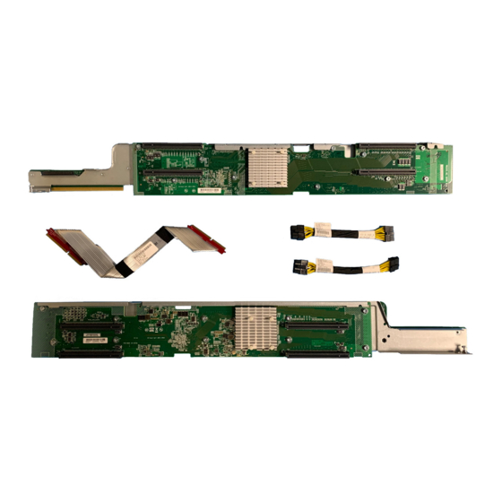
Page 33: Server Shipping Carton Contents
For server -specific information, see "Hardware options installation." Installing the operating system To operate properly, the server must have a supported operating system installed. For the latest information on operating system support, see the Hewlett Packard Enterprise website (http://www.hpe.com/info/ supportos). Server shipping carton contents... -
Page 34: Installing The System Software
IMPORTANT: HPE ProLiant XL servers do not support operating system installation with Intelligent Provisioning, but they do support the maintenance features. For more information, see "Performing Maintenance" in the HPE Intelligent Provisioning User Guide and online help. To install an operating system on the server , use one of the following methods: •... -
Page 35: Hardware Options Installation
Hardware options installation Product QuickSpecs For more information about product features, specifications, options, configurations, and compatibility, see the product QuickSpecs on the Hewlett Packard Enterprise website. Introduction If more than one option is being installed, read the installation instructions for all the hardware options and identify similar steps to streamline the installation process. -
Page 36: Processor Option
2. Prepare the drive. 3. Install the drive. 4. Determine the status of the drive from the drive LED definitions. To configure arrays, see the HPE Smart Storage Administrator User Guide on the Hewlett Packard Enterprise website. Processor option Processor and heatsink installation warnings and cautions... -
Page 37: Installing The Processor And Heatsink
Installing the processor and heatsink About this task For more information about product features, specifications, options, configurations, and compatibility, see the product QuickSpecs on the Hewlett Packard Enterprise website . To install the component: Procedure Back up all server data. Power down the server . - Page 38 CAUTION: To avoid damage to the processor, do not touch the bottom of the processor, especially the contact area. 10. Install the processor. Verify that the processor is fully seated in the processor retaining bracket by visually inspecting the processor installation guides on either side of the processor. THE PINS ON THE SYSTEM BOARD ARE VERY FRAGILE AND EASILY DAMAGED.
- Page 39 CAUTION: Do not press down on the processor. Pressing down on the processor might damage the processor socket and the system board. Press only in the area indicated on the processor retaining bracket. 11. Close the processor retaining bracket. When the processor is installed properly inside the processor retaining bracket, the processor retaining bracket clears the flange on the front of the socket.
-
Page 40: Memory Options
CAUTION: Heatsinks specified for processor 1 and 2 are not interchangeable. Be sure to note the appropriate orientation on the heatsink label. CAUTION: Heatsink retaining screws should be tightened or loosened in diagonally opposite pairs (in an "X" pattern). Do not overtighten the screws as this can damage the board, connectors, or screws. 14. -
Page 41: Dimm Specifications
All types are referred to as DIMMs when the information applies to all types. When specified as LRDIMM or RDIMM, the information applies to that type only. All memory installed in the node must be the same type. DIMM specifications DIMM specifications Type Rank... -
Page 42: Memory Subsystem Architecture
Memory subsystem architecture The memory subsystem in this server is divided into channels. Each processor supports four channels, and each channel supports two DIMM slots, as shown in the following table. Channel Population order Slot number Single-, dual-, and quad-rank DIMMs To understand and configure memory protection modes properly, an understanding of single-, dual-, and quad-rank DIMMs is helpful. -
Page 43: Memory Configurations
Advanced Memory Protection options are configured in the BIOS/Platform Configuration (RBSU). If the requested AMP mode is not supported by the installed DIMM configuration, the server boots in Advanced ECC mode. For more information, see the HPE UEFI System Utilities User Guide for ProLiant Gen9 Servers on the Hewlett Packard Enterprise website. -
Page 44: Online Spare Memory Configuration
Online Spare memory configuration Online spare memory provides protection against degraded DIMM s by reducing the likelihood of uncorrected memory errors. This protection is available without any operating system support. Online spare memory protection dedicates one rank of each memory channel for use as spare memory. The remaining ranks are available for OS and application use. -
Page 45: Installing A Dimm
Installing a DIMM Procedure Back up all server data. Power down the server . Disconnect all peripheral cables from the server . Remove the server from the chassis . Place the server on a sturdy, level surface. Remove the access panel. Remove the air baffle. - Page 46 Procedure Back up all server data. Power down the server . Disconnect all peripheral cables from the server front panel. Remove the server from the chassis . Place the server on a sturdy, level surface. Remove the access panel. If installed, remove the Smart Storage Battery: a.
- Page 47 c. Disconnect the power cable from the GPU, and then remove the GPU from the server. 11. Remove all GPU blanks: a. Loosen the captive screw. b. Using both hands, gently pull the tab and the rear of the GPU blank. c.
- Page 48 • Slot 10 14. If installed, remove the HPE Smart Array P542D controller module: a. Pull up the pin. b. Rotate the handle counter-clockwise. Hardware options installation...
- Page 49 c. Push down the pin. d. Slide the module out of the PCIe slot and remove it from the server. 15. Disconnect and remove the 8:1 riser sideband cable. Hardware options installation...
- Page 50 16. Disconnect the power cables from the 8:1 risers. 17. Remove the riser cross bracket: a. Loosen the captive screws. b. Remove the bracket from the server. Hardware options installation...
- Page 51 18. Remove the power riser. 19. Remove the right 8:1 PCI riser module: a. Loosen the captive screw. b. Using both hands, lift and remove the PCI riser module from the server. Hardware options installation...
- Page 52 20. Remove the left 8:1 PCI riser module: a. Loosen the captive screw. b. Using both hands, lift and remove the PCI riser module from the server. 21. Install the left 4:1 PCI riser module: a. Slide the PCI riser module into the server, and then use both hands to press downward to secure the PCI riser module in the connectors.
- Page 53 22. Install the right 4:1 PCI riser module: a. Slide the PCI riser module into the server, and then use both hands to press downward to secure the PCI riser module in the connectors. b. Tighten the captive screw. 23. Install the power riser. Hardware options installation...
- Page 54 24. Install the riser cross bracket: a. Align the captive screws with the screw holes. b. Tighten the captive screws. 25. Connect the power cables to the right and left PCI riser modules. Hardware options installation...
- Page 55 26. If removed, install the HPE Smart Array P542D controller module. 27. If removed, install the expansion board. 28. Connect any required internal cables. 29. Install the drive cage assembly. 30. Connect all cables to the drive backplane. 31. Install all GPUs and GPU blanks.
-
Page 56: Installing The 8:1 Pci Riser Modules
Installing the 8:1 PCI riser modules About this task To install the component: Procedure Back up all server data. Power down the server . Disconnect all peripheral cables from the server front panel. Remove the server from the chassis . Place the server on a sturdy, level surface. - Page 57 Remove the air baffle. IMPORTANT: Remove all GPUs, GPU blanks, and expansion boards before removing the PCI riser modules. 10. Remove the side panel. 11. Remove all GPUs: a. Loosen the captive screw. b. Using both hands, gently pull the tab and the rear support bracket to slide out the GPU to access the power cable.
- Page 58 c. Slide out the GPU blank from the server. 13. Remove the drive cage assembly. 14. Remove all expansion boards: a. Disconnect any internal cables that are connected to the riser modules. b. Remove the expansion board. • Slot 9 •...
- Page 59 15. If installed, remove the HPE Smart Array P542D controller module: a. Pull up the pin. b. Rotate the handle counter-clockwise. c. Push down the pin. d. Slide the module out of the PCIe slot and remove it from the server.
- Page 60 16. Disconnect the power cables from the 4:1 risers. 17. Remove the riser cross bracket: a. Loosen the captive screws. b. Remove the bracket from the server. Hardware options installation...
- Page 61 18. Remove the power riser. 19. Remove the right 4:1 PCI riser module: a. Loosen the captive screw. b. Using both hands, lift and remove the PCI riser module from the server. Hardware options installation...
- Page 62 20. Remove the left 4:1 PCI riser module: a. Loosen the captive screw. b. Using both hands, lift and remove the PCI riser module from the server. 21. Install the left 8:1 PCI riser module: a. Slide the PCI riser module into the server, and then use both hands to press downward to secure the PCI riser module in the connectors.
- Page 63 22. Install the right 8:1 PCI riser module: a. Slide the PCI riser module into the server, and then use both hands to press downward to secure the PCI riser module in the connectors. b. Tighten the captive screw. 23. Install the power riser. Hardware options installation...
- Page 64 24. Install the riser cross bracket: a. Align the captive screws with the screw holes. b. Tighten the captive screws. 25. Connect the power cables to the right and left PCI riser modules. Hardware options installation...
- Page 65 26. If removed, install the HPE Smart Array P542D controller module. 27. If removed, install the expansion board. 28. Connect any required internal cables. 29. Install the drive cage assembly. 30. Connect all cables to the drive backplane. 31. Install all GPUs and GPU blanks.
-
Page 66: Storage Controller Options
• Install one storage controller per server. • The HPE H240/H241 host bus adapter or HPE P440/P441 Smart Array controller can be installed in slot 9 or slot 10. • Install the P542D Storage Controller module into slot 11. - Page 67 11. Install the HPE Smart Array P542D Controller module: a. Slide the module into the PCIe slot. b. Pull up the pin. c. Rotate the handle clockwise. d. Push down the pin. Hardware options installation...
- Page 68 12. Install the drive cage assembly. 13. Connect the cables to the drive backplane: a. Connect the power cable. b. Connect the Mini-SAS cables. Install the cables according to their labels as MINI-SAS 0 or MINI-SAS 1. The labels are on both the cables and their connections. 14.
-
Page 69: Installing An Hpe Host Bus Adapter
Installing an HPE Host Bus Adapter About this task To install the component: Procedure Back up all server data. Power down the server . Disconnect all peripheral cables from the server . Remove the server from the chassis. Place the server on a sturdy, level surface. - Page 70 12. Connect the Mini-SAS cables to the host-bus adapter. Install the cables according to their labels as Port 1 or Port 2. The labels are on both the cables and their connections. 13. Install the host-bus adapter. • Slot 9 Hardware options installation...
- Page 71 • Slot 10 14. Install the drive cage assembly. 15. Connect the cables to the drive backplane: a. Connect the power cable. b. Connect the Mini-SAS cables. Install the cables according to their labels as MINI-SAS 0 or MINI-SAS 1. The labels are on both the cables and their connections. Hardware options installation...
-
Page 72: Installing The Smart Array P440 Controller
16. Install the air baffle. If the 4:1 riser signal cable or Smart Storage Battery are installed in the air baffle, reconnect the cables to the risers. For more information, see "Installing the air baffle." 17. Install the access panel. 18. - Page 73 11. Remove the full-height bracket from the storage controller and attach the low-profile bracket. For more information, see the documentation that ships with the option. 12. If you intend to use an FBWC module, install the module on the storage controller. Depending on the controller model, the cable connector on the cache module might be facing up or down when the module is installed on the controller board.
- Page 74 NOTE: A second processor is required to install a storage controller in slot 10 of the right 4:1 PCI riser module. 13. Remove the PCI blank. • Slot 9 • Slot 10 Hardware options installation...
- Page 75 14. Connect the Mini-SAS Y-cable to the storage controller. 15. Install the storage controller. • Slot 9 Hardware options installation...
- Page 76 • Slot 10 16. If the cache module is installed on the Smart Array controller, connect the cache module backup power cable to the riser board. 17. Install the drive cage assembly. 18. Connect the cables to the drive backplane: a.
-
Page 77: Installing The B140I Sata Cables
19. Install the air baffle. If the 4:1 riser signal cable or Smart Storage Battery are installed in the air baffle, reconnect the cables to the risers. For more information, see "Installing the air baffle." 20. Install the access panel. 21. -
Page 78: Installing An Hpe Smart Storage Battery
3. Remove the server from the chassis. 4. Place the server on a sturdy, level surface. 5. Remove the access panel. 6. Install the HPE Smart Storage Battery: a. Install the battery into the holder. b. Ensure that the release clip is closed and locked. -
Page 79: Gpu Accelerator Options
The mixing of different GPU accelerator models is not supported. • If three or more NVIDIA Tesla K80 GPUs or NVIDIA Tesla P40 GPUs are installed on one side of the HPE ProLiant XL270d Gen9 Accelerator Tray, the inlet ambient temperature must be maintained at or below 30°C (86°F). -
Page 80: High-Performance Mode For 4:1 And 8:1 Pci Riser Modules
• If three or more NVIDIA Tesla P100 GPUs are installed on one side of the HPE ProLiant XL270d Gen9 Accelerator Tray, the inlet ambient temperature must be maintained at or below 25°C (77°F). • A maximum of four K80 GPUs are allowed in a 8:1 PCI riser module configuration. - Page 81 CAUTION: To prevent improper cooling and thermal damage, do not operate the server unless all bays are populated with either a component or a blank. Remove the GPU: a. Loosen the captive screw. b. Using both hands, gently pull the tab and the rear support bracket to slide out the GPU to access the power cable.
-
Page 82: Installing The Nvidia K40 Gpu Enablement Kit
Installing the NVIDIA K40 GPU enablement kit About this task Depending on the existing server configuration, some or all of the following procedures may apply. For more information about product features, specifications, options, configurations, and compatibility, see the product QuickSpecs on the Hewlett Packard Enterprise website . To install the component: Procedure Back up all server data. - Page 83 c. Disconnect the power cable from the GPU, and then remove the GPU from the server. 10. If the existing GPU power cables do not support the NVIDIA K40 GPUs, remove the cables from the server: a. Remove the screws to release the retention springs. Keep the screws for later use. b.
- Page 84 d. Remove the power cables from the server. e. Repeat the procedure on the other side of the server. 11. Install the front support bracket onto the GPU. 12. To install the long GPU power cables for slots 1 and 2, do the following: a.
- Page 85 e. To install the long GPU power cables for slots 5 and 6, repeat the procedure on the other side of the server. 13. To install the short GPU power cables for slots 3 and 4, do the following: a. Route the short GPU power cables into the server. b.
- Page 86 c. Install the GPUs and tighten the thumbscrews. 15. If installing GPUs into slots 5 and 6, repeat the procedure on the other side of the server. 16. To install GPUs into slots 3 and 4, do the following: a. Align each GPU with the guide features in the server, and then slide the GPUs halfway into the server. b.
-
Page 87: Installing The Nvidia K80/M40/P40/P100 Gpu Enablement Kit
c. Install the GPUs and tighten the thumbscrews. 17. If installing GPUs into slots 7 and 8, repeat the procedure on the other side of the server. CAUTION: To prevent improper cooling and thermal damage, do not operate the server unless all bays are populated with either a component or a blank. - Page 88 For more information about product features, specifications, options, configurations, and compatibility, see the product QuickSpecs on the Hewlett Packard Enterprise website . To install the component: Procedure Back up all server data. Power down the server . Disconnect all peripheral cables from the server front panel. Remove the server from the chassis.
- Page 89 a. Loosen the captive screw. b. Using both hands, gently pull the tab and the rear support bracket to slide out the GPU to access the power cable. c. Disconnect the power cable from the GPU, and then remove the GPU from the server. 10.
- Page 90 d. Remove the power cables from the server. e. Repeat the procedure on the other side of the server. 11. Remove the existing front support bracket. 12. Install the front support bracket onto the GPU. Hardware options installation...
- Page 91 13. To install the long GPU power cables for slots 1 and 2, do the following: a. Route the long GPU power cables into the server. b. Connect the power cables to the power distribution board. c. Secure the power cables in the clip. d.
- Page 92 d. To install the short GPU power cables for slots 7 and 8, repeat the procedure on the other side of the server. 15. To install GPUs into slots 1 and 2, do the following: a. Align each GPU with the guiding features in the server, and then slide the GPUs halfway into the server.
- Page 93 16. If installing GPUs into slots 5 and 6, repeat the procedure on the other side of the server. 17. To install GPUs into slots 3 and 4, do the following: a. Align each GPU with the guiding features in the server, and then slide the GPUs halfway into the server.
-
Page 94: Installing The Amd Firepro S9150 Gpu Enablement Kit
18. If installing GPUs into slots 7 and 8, repeat the procedure on the other side of the server. CAUTION: To prevent improper cooling and thermal damage, do not operate the server unless all bays are populated with either a component or a blank. 19. - Page 95 CAUTION: The mixing of different GPU accelerator models is not supported. If AMD FirePro S9150 GPUs are already installed in the server, and additional AMD FirePro S9150 GPUs are now being installed, remove the GPU blank: a. Loosen the captive screw. b.
- Page 96 c. Disconnect the power cables from the power distribution board. • Long GPU power cables • Short GPU power cables d. Remove the power cables from the server. e. Repeat the procedure on the other side of the server. 11. To install the front support bracket onto the GPU: a.
- Page 97 b. Remove the existing front support bracket. c. Install the front support bracket onto the GPU. Hardware options installation...
- Page 98 d. Reinstall the accelerator cover. 12. To install the long GPU power cables for slots 1 and 2, do the following: a. Route the long GPU power cables into the server. b. Connect the power cables to the power distribution board. c.
- Page 99 d. To install the short GPU power cables for slots 7 and 8, repeat the procedure on the other side of the server. 14. To install GPUs into slots 1 and 2, do the following: a. Align each GPU with the guiding features in the server, and then slide the GPUs halfway into the server.
- Page 100 15. If installing GPUs into slots 5 and 6, repeat the procedure on the other side of the server. 16. To install GPUs into slots 3 and 4, do the following: a. Align each GPU with the guiding features in the server, and then slide the GPUs halfway into the server.
-
Page 101: Expansion Board Options
• Install the P542D Smart Array Storage Controller module into slot 11. For more information, see "Installing the HPE Smart Array P542D Controller module." For more information on the riser board slot specifications, see "PCI riser module components." For more information about product features, specifications, options, configurations, and compatibility, see the product QuickSpecs on the Hewlett Packard Enterprise website . -
Page 102: Installing The Expansion Board
Installing the expansion board About this task CAUTION: Hewlett Packard Enterprise recommends performing a complete backup of all server data before performing a controller or adapter installation or removal. To install the component: Procedure Back up all server data. Power down the server . Disconnect all peripheral cables from the server . - Page 103 11. Connect any required cables to the expansion board. 12. Install the expansion board. • Slot 9 • Slot 10 Hardware options installation...
-
Page 104: Dedicated Ilo Management Port Module Option
13. Connect all necessary internal cabling to the expansion board. For more information on these cabling requirements, see the documentation that ships with the option. 14. Install the drive cage assembly. 15. Connect all cables to the drive backplane. 16. Install the air baffle. If the 4:1 riser signal cable or Smart Storage Battery are installed in the air baffle, reconnect the cables to the risers. - Page 105 WARNING: To reduce the risk of personal injury from hot surfaces, allow the internal system components to cool before touching them. CAUTION: Electrostatic discharge can damage electronic components. Be sure you are properly grounded before beginning this procedure. To install the component: Procedure Back up all server data.
- Page 106 13. Install the dedicated iLO management port card. 14. If removed from slot 10, install the expansion board. 15. Connect any required cables. 16. Install the drive cage assembly. 17. Connect all cables to the drive backplane. 18. Install the air baffle. If the 4:1 riser signal cable or Smart Storage Battery are installed in the air baffle, reconnect the cables to the risers.
-
Page 107: Enabling The Dedicated Ilo Management Module
Enabling the dedicated iLO management module About this task The onboard NIC 1/shared iLO connector is set as the default system iLO connector. To enable the dedicated iLO management module, use the iLO 4 Configuration Utility accessible within the UEFI System Utilities. For more information on the UEFI System Utilities, see the UEFI documentation on the Hewlett Packard Enterprise website. -
Page 108: Installing The Trusted Platform Module Board
Installing the Trusted Platform Module board About this task WARNING: To reduce the risk of personal injury from hot surfaces, allow the drives and the internal system components to cool before touching them. To install the component: Procedure Back up all server data. Power down the server . -
Page 109: Retaining The Recovery Key/Password
10. Install the TPM security rivet by pressing the rivet firmly into the system board. 11. If removed from slot 9, install the expansion board. 12. Connect any required internal cables. 13. Install the drive cage assembly. 14. Connect all cables to the drive backplane. 15. -
Page 110: Enabling The Trusted Platform Module
password is required to enter Recovery Mode after BitLocker detects a possible compromise of system integrity. To help ensure maximum security, observe the following guidelines when retaining the recovery key/ password: • Always store the recovery key/password in multiple locations. •... -
Page 111: Cabling
Cabling Power cabling Drive backplane power cabling PCI riser module power cabling GPU power cabling The GPU power cables have retention springs. For more information on installing the GPU power cables, see "GPU accelerator options." • Left GPU power cabling for NVIDIA K40 and AMD S9150 GPUs Cabling... - Page 112 Item Description Part number GPU 1 power cable (8 pin and 6 pin to 8 pin long) 857501-001 GPU 2 power cable (8 pin and 6 pin to 8 pin long 857501-001 GPU 3 power cable (8 pin and 6 pin to 8 pin short) 853655-001 GPU 4 power cable (8 pin and 6 pin to 8 pin short) 853655-001...
- Page 113 Item Description Part number GPU 1 power cable (8 pin to 8 pin long) 857500-001 GPU 2 power cable (8 pin to 8 pin long) 857500-001 GPU 3 power cable (8 pin to 8 pin short) 853650-001 GPU 4 power cable (8 pin to 8 pin short) 853650-001 •...
-
Page 114: Fan Power Cabling
Fan power cabling Item Description Left fan power cable Right fan power cable Storage cabling B140i SATA cabling Fan power cabling... -
Page 115: Smart Array P542D Controller Cabling
Item Description Connection SATA cable MB_SATA1 on the system board to Mini_SAS_0 on the drive backplane SATA cable MB_SATA2 on the system board to Mini_SAS_1 on the drive backplane Smart Array P542D Controller cabling Item Description Connection Mini-SAS cable Port 3 connector to Mini_SAS_0 connector on the drive backplane Mini-SAS cable Port 4 connector to Mini_SAS_1 connector on the... -
Page 116: Smart Array P440 Controller Cabling
• Slot 10 Item Description Connection Mini-SAS cable Port 1 to Mini_SAS_0 connector on the drive backplane Mini-SAS cable Port 2 to Mini_SAS_1 connector on the drive backplane Smart Array P440 Controller cabling • Slot 9 Smart Array P440 Controller cabling... - Page 117 • Slot 10 Cabling...
-
Page 118: Smart Storage Battery Cabling
Smart Storage Battery cabling FBWC module cabling The FBWC solution is a separately purchased option. This server only supports FBWC module installation when a Smart Array P-Series controller is installed. Depending on the controller option installed, the actual storage controller connectors might look different from what is shown in this section. -
Page 119: Pci Riser Module Signal Cabling
PCI riser module signal cabling 4:1 riser signal cable PCI riser module signal cabling... -
Page 120: 8:1 Riser Sideband Cable
8:1 riser sideband cable 8:1 riser sideband cable... -
Page 121: Software And Configuration Utilities
QuickSpecs on the Hewlett Packard Enterprise website. HPE iLO iLO is a remote server management processor embedded on the system boards of HPE ProLiant and Synergy servers. iLO enables the monitoring and controlling of servers from remote locations. HPE iLO management is a powerful tool that provides multiple ways to configure, update, monitor, and repair servers remotely. -
Page 122: Ilo Restful Api Support
Intelligent Provisioning User Guide on the Hewlett Packard Enterprise website iLO RESTful API support HPE iLO 4 firmware version 2.00 and later includes the iLO RESTful API. The iLO RESTful API is a management interface that server management tools can use to perform configuration, inventory, and monitoring of the ProLiant server via iLO. -
Page 123: Hpe Insight Online Direct Connect
For more information, see the product documentation on the Hewlett Packard Enterprise website. Insight Online HPE Insight Online is a capability of the Support Center portal. Combined with Insight Remote Support central connect or Insight Online direct connect, it automatically aggregates device health, asset, and support information with contract and warranty information, and then secures it in a single, personalized dashboard that is viewable from anywhere at any time. -
Page 124: Insight Diagnostics Survey Functionality
The SPP is a comprehensive systems software (drivers and firmware) solution delivered as a single package with major server releases. This solution uses SUM as the deployment tool and is tested on all supported ProLiant servers including HPE ProLiant Gen8 and later servers. SPP allows the following operating modes: •... -
Page 125: Smart Update Manager
Smart Update Manager SUM is a product used to install and update firmware, drivers, and systems software on ProLiant servers. SUM provides a GUI, a command-line scriptable interface, and an interactive command-line scriptable interface. The interfaces allow you to deploy firmware, drivers, and software for supported servers. For more information about SUM, see the product page on the Hewlett Packard Enterprise website. -
Page 126: Flexible Boot Control
Flexible boot control This feature enables you to do the following: • Add Boot Options: ◦ Browse all FAT16 and FAT32 file systems. ◦ To add a new UEFI boot option, select an X64 UEFI application with an .EFI extension. For example, adding an OS boot loader or other UEFI application as a new UEFI boot option. -
Page 127: Embedded Uefi Shell
These features enhance the capabilities of the UEFI System Utilities. For more information, see the following documents: • UEFI Shell User Guide for HPE ProLiant Gen9 Servers on the Hewlett Packard Enterprise website • UEFI Shell Specification on the UEFI website Embedded Diagnostics option The system BIOS in all ProLiant Gen9 servers includes an Embedded Diagnostics option in the ROM. -
Page 128: Utilities And Features
ProLiant Gen8 servers, HPE SSA replaces ACU with an enhanced GUI and additional configuration features. The HPE SSA exists in three interface formats: the HPE SSA GUI, the HPE SSA CLI, and HPE SSA Scripting. Although all formats provide support for configuration tasks, some of the advanced tasks are available in only one format. -
Page 129: External Usb Functionality
For maximum compatibility of USB 3.0 devices with all operating systems, Hewlett Packard Enterprise provides a configuration setting for USB 3.0 Mode. Auto is the default setting. This setting impacts USB 3.0 devices when connected to USB 3.0 ports in the following manner: •... -
Page 130: Fwupdate Utility
• Firmware Update application in the UEFI System • Online Flash components Product entitlement is required to perform updates. FWUPDATE utility The FWUPDATE utility enables you to upgrade the system firmware (BIOS). To use the utility to upgrade the firmware: 1. -
Page 131: Firmware Update Application In The Uefi System Utilities
Hewlett Packard Enterprise website. To locate the drivers for a particular server, go to the Hewlett Packard Enterprise Support Center website. Under Select your HPE product, enter the product name or number and click Go. Software and firmware Update software and firmware before using the server for the first time, unless any installed software or components require an older version. -
Page 132: Operating System Version Support
HPE Support Services enables you to choose the right service level, length of coverage, and response time to fit your business needs. Connect to HPE to help prevent problems and solve issues faster. By connecting, you will receive 24x7 monitoring, prefailure alerts, automatic call logging, and automatic parts dispatch. - Page 133 • Upcoming hardware and software changes • Bulletins • Patches Let us know what Hewlett Packard Enterprise commercial products you own and we will send you the latest updates to keep your business running smoothly. For more information, see the Hewlett Packard Enterprise website. Software and configuration utilities...
-
Page 134: System Battery
System battery System battery overview If the server no longer automatically displays the correct date and time, then replace the battery that provides power to the real-time clock. Under normal use, battery life is 5 to 10 years. WARNING: The computer contains an internal lithium manganese dioxide, a vanadium pentoxide, or an alkaline battery pack. - Page 135 Locate the battery on the system board. 10. If the system battery is secured by a metal tab, do the following: a. Use your finger or a small flat-bladed, nonconductive tool to press the metal tab. This will partially release the battery from the socket. b.
-
Page 136: Troubleshooting
• Simplified Chinese The HPE ProLiant Gen9 Troubleshooting Guide, Volume II: Error Messages provides a list of error messages and information to assist with interpreting and resolving error messages on ProLiant servers and server blades. To view the guide, select a language: •... -
Page 137: Warranty And Regulatory Information
Warranty and regulatory information Warranty information HPE ProLiant and x86 Servers and Options HPE Enterprise Servers HPE Storage Products HPE Networking Products Regulatory information Belarus Kazakhstan Russia marking Manufacturer and Local Representative Information Manufacturer information: Hewlett Packard Enterprise Company, 3000 Hanover Street, Palo Alto, CA 94304 U.S. -
Page 138: Turkey Rohs Material Content Declaration
Manufacturing date: The manufacturing date is defined by the serial number. CCSYWWZZZZ (serial number format for this product) Valid date formats include: • YWW, where Y indicates the year counting from within each new decade, with 2000 as the starting point; for example, 238: 2 for 2002 and 38 for the week of September 9. -
Page 139: Electrostatic Discharge
Electrostatic discharge Preventing electrostatic discharge About this task To prevent damaging the system, be aware of the precautions you must follow when setting up the system or handling parts. A discharge of static electricity from a finger or other conductor may damage system boards or other static-sensitive devices. -
Page 140: Specifications
30°C (86°F). For more information, see " GPU accelerator population guidelines" If three or more NVIDIA Tesla P100 GPUs are installed on one side of the HPE ProLiant XL270d Gen9 Accelerator Tray, the inlet ambient temperature must be maintained at or below 25°C (77°F). For more information, see "... -
Page 141: Support And Other Resources
Support and other resources Accessing Hewlett Packard Enterprise Support • For live assistance, go to the Contact Hewlett Packard Enterprise Worldwide website: http://www.hpe.com/assistance • To access documentation and support services, go to the Hewlett Packard Enterprise Support Center website: http://www.hpe.com/support/hpesc Information to collect •... -
Page 142: Customer Self Repair
IMPORTANT: Access to some updates might require product entitlement when accessed through the Hewlett Packard Enterprise Support Center. You must have an HPE Passport set up with relevant entitlements. Customer self repair Hewlett Packard Enterprise customer self repair (CSR) programs allow you to repair your product. If a CSR part needs to be replaced, it will be shipped directly to you so that you can install it at your convenience. -
Page 143: Regulatory Information
Documentation Feedback (docsfeedback@hpe.com). When submitting your feedback, include the document title, part number, edition, and publication date located on the front cover of the document. For online help content, include the product name, product version, help edition, and publication date located on the legal notices page. -
Page 144: Acronyms And Abbreviations
DIMMs per channel EuroAsian Economic Commission FBWC flash-backed write cache graphics processing unit HPE APM HPE Advanced Power Manager HPE SIM HPE Systems Insight Manager HPE SSA HPE Smart Storage Administrator International Electrotechnical Commission Integrated Lights-Out Acronyms and abbreviations... - Page 145 Integrated Management Log International Organization for Standardization large form factor LAN on Motherboard LRDIMM load reduced dual in-line memory module nonmaskable interrupt NVRAM nonvolatile memory Onboard Administrator PCIe Peripheral Component Interconnect Express power distribution board power distribution unit POST Power-On Self-Test RBSU ROM-Based Setup Utility Rack control management...
- Page 146 serial attached SCSI SATA serial ATA small form factor Systems Insight Manager Service Pack for ProLiant Smart Update Manager serial, USB, video TMRA recommended ambient operating temperature Trusted Platform Module UEFI Unified Extensible Firmware Interface unit identification universal serial bus Version Control Agent VCRM Version Control Repository Manager...
Need help?
Do you have a question about the ProLiant XL270d Gen9 and is the answer not in the manual?
Questions and answers