Table of Contents
Advertisement
Quick Links
SICAM
Class A Power Quality
Instrument and Power
Monitoring Device SICAM
Q100 7KG95xx
V02.30
Manual
E50417-H1040-C522-A8
Preface
Open Source Software
Table of Contents
Introduction
Device Functions
Security
Commissioning and First Steps
Troubleshooting, Repair, and Fallback
Mode
Maintenance, Storage, Transport
Technical Data
Operational Indications and Operating
Parameters
Glossary
1
2
3
4
5
6
7
8
Advertisement
Table of Contents
Troubleshooting

Related Manuals for Siemens SICAM Q100 7KG95 Series


Summary of Contents for Siemens SICAM Q100 7KG95 Series
- Page 1 Preface Open Source Software Table of Contents SICAM Introduction Class A Power Quality Device Functions Instrument and Power Monitoring Device SICAM Security Q100 7KG95xx Commissioning and First Steps Troubleshooting, Repair, and Fallback Mode V02.30 Maintenance, Storage, Transport Technical Data Manual Operational Indications and Operating Parameters Glossary...
- Page 2 Document version: E50417-H1040-C522-A8.04 Trademarks Edition: 09.2020 SIPROTEC, DIGSI, SIGRA, SIGUARD, SIMEAS SAFIR, SICAM, Version of the product described: V02.30 and MindSphere are trademarks of Siemens. Any unauthor- ized use is prohibited.
-
Page 3: Preface
This conformity has been proved by tests performed according to the Council Directive in accordance with the generic standard EN 61000-6-5 (for EMC directive) and with the product standard EN 62586-1 (for Low Voltage Directive) by Siemens AG. The device is designed and manufactured for application in an industrial environment. - Page 4 Preface 90459 Nuremberg Internet: www.siemens.com/poweracademy Germany Notes on Safety This document is not a complete index of all safety measures required for operation of the equipment (module or device). However, it comprises important information that must be followed for personal safety, as well as to avoid material damage.
- Page 5 Preface Problem-free and safe operation of the product depends on the following: • Proper transport • Proper storage, setup and installation • Proper operation and maintenance When electrical equipment is operated, hazardous voltages are inevitably present in certain parts. If proper action is not taken, death, severe injury or property damage can result: •...
- Page 6 SICAM, SICAM Q100 7KG95xx, Manual E50417-H1040-C522-A8, Edition 09.2020...
-
Page 7: Open Source Software
License Conditions provide for it you can order the source code of the Open Source Software from your Siemens sales contact – against payment of the shipping and handling charges – for a period of at least 3 years after purchase of the product. We are liable for the product including the Open Source Software contained in it pursuant to the license conditions applicable to the product. - Page 8 SICAM, SICAM Q100 7KG95xx, Manual E50417-H1040-C522-A8, Edition 09.2020...
-
Page 9: Table Of Contents
Table of Contents Preface................................3 Open Source Software..........................7 Introduction..............................17 User Information.......................18 Device Overview....................... 21 Device Design........................25 Device Functions............................29 General Information on Measuring and Recording............. 30 2.1.1 Measuring System....................... 30 2.1.2 Recording System......................33 2.1.3 Measurands ........................34 2.1.3.1 Operational Measured Quantities Depending on the Connection Types....34 2.1.3.2 Harmonics, Interharmonics, and Emissions Depending on the Connection Types..36 2.1.3.3... - Page 10 Table of Contents Measurement and Evaluation Functions................62 2.3.1 AC Operational Values....................62 2.3.1.1 Function Description....................62 2.3.1.2 Configuration and Evaluation via User Interface............62 2.3.1.3 Configuration and Evaluation via Display..............63 2.3.2 Harmonics, Interharmonics, Direction Harmonics............64 2.3.2.1 Function Description....................64 2.3.2.2 Configuration and Evaluation via User Interface............67 2.3.2.3...
- Page 11 Table of Contents 2.5.3 Waveform Recorder....................128 2.5.3.1 Function Description.................... 128 2.5.3.2 Configuration and Evaluation via User Interface............131 2.5.4 Trend Recorder......................134 2.5.4.1 Function Description.................... 134 2.5.4.2 Configuration and Evaluation via User Interface............135 2.5.5 Event Recorder......................137 2.5.5.1 Function Description.................... 137 2.5.5.2 Reset PQ Events....................
- Page 12 Table of Contents 2.8.3 Modbus Slave Devices....................175 2.8.3.1 Function Description.................... 175 2.8.3.2 Configuration and Evaluation via User Interface............175 Modbus TCP to Modbus RTU Gateway................188 2.9.1 Function Description....................188 2.9.2 Configuration via User Interface.................190 2.9.3 Configuration and Evaluation via Display..............193 2.9.4 Diagnosis Modbus TCP to Modbus RTU Gateway............193 2.10 Other Device Functions....................
- Page 13 Table of Contents Password Management....................260 3.4.1 Function Description....................260 3.4.2 Configuration via the User Interface................260 Audit Log........................262 3.5.1 Function Description....................262 3.5.2 Event Types....................... 262 3.5.3 View via User Interface....................263 Syslog..........................265 3.6.1 Function Description....................265 3.6.2 Configuration via User Interface.................266 3.6.3 View via Syslog Server....................
- Page 14 Table of Contents 4.13.3 Configuration of the Device..................309 4.13.3.1 Introduction......................309 4.13.3.2 Get Device Configuration..................310 4.13.3.3 Open Configuration from File................311 4.13.3.4 Finish Configuration.....................313 4.13.3.5 Access to the Passive Set of Parameters by Multiple Users........317 4.14 Operation via Display...................... 319 4.14.1 General Operating Instructions..................
- Page 15 Table of Contents 8.4.2 User-Defined Screen....................355 Energy Management.......................357 8.5.1 Load Profile....................... 357 8.5.2 Energy Profile......................357 8.5.3 Tariffs........................357 8.5.4 Energy Upper Limit....................358 8.5.5 Energy Freeze and Reset.................... 358 8.5.6 CO2 Emissions......................358 Recording and Reporting....................359 8.6.1 Event Recorders......................359 8.6.2 Waveform Recorder and Trigger Management............359 8.6.3...
- Page 16 SICAM, SICAM Q100 7KG95xx, Manual E50417-H1040-C522-A8, Edition 09.2020...
-
Page 17: Introduction
Introduction User Information Device Overview Device Design SICAM, SICAM Q100 7KG95xx, Manual E50417-H1040-C522-A8, Edition 09.2020... -
Page 18: User Information
Introduction 1.1 User Information User Information Application The SICAM device is a multifunctional device for detecting, reporting, and analyzing measured values and events. The device is characterized by the following properties: • Power quality (PQ) instrument, IEC 61000-4-30, Ed. 3, class A and IEC 62586-1/2 Ed. 2 •... - Page 19 Introduction 1.1 User Information Power quality parameters • Power frequency • Magnitude of supply voltage • Flicker • Supply voltage dips, swells, and interruptions • Voltage unbalance • Voltage harmonics and interharmonics • Rapid voltage changes (RVC) • Current magnitude •...
- Page 20 Introduction 1.1 User Information Energy Management As part of the energy management, the device records load profiles according to the Fixed Block or Rolling Block method for all power quantities. Additionally, it is possible to calculate up to 8 tariffs (TOU = Time of Use).
-
Page 21: Device Overview
Introduction 1.2 Device Overview Device Overview It is a multifunctional device for detection, calculation, recording, evaluation, display, and transmission of measured electrical quantities with the following properties: Device Properties All devices consistently provide the following properties: • Device type: – Class A Power Quality Instrument and Power Monitoring Device, with measured-value recorders and exchangeable 2 GB microSD card –... - Page 22 Introduction 1.2 Device Overview • Measurements for evaluation and supervision – Minimum/mean/maximum values – Event detection: voltage dips, voltage swells, voltage interruptions – Limit violations – Energy management (load profiles and tariffs) – Rapid voltage change (RVC) – Transient detection •...
- Page 23 Ordering Information You can obtain the order information for the device from the catalog SICAM – Power Quality and Measure- ments with an order key or from https://new.siemens.com/global/en/products/energy/energy-automation- and-smart-grid/power-quality-measurement.html. NOTE This document describes all functions and features available in the device with a maximum equipment. You can find the individual equipment of your device in the ordering variant or the catalog mentioned above.
- Page 24 Introduction 1.2 Device Overview Table 1-1 Cable Length Cable Length Ethernet Patch Cable (Double Shielded (SFPT), LAN 0.5 m Connector Plugs on Both Sides) 1.0 m 2.0 m 3.0 m 5.0 m 10.0 m 15.0 m 20.0 m SICAM, SICAM Q100 7KG95xx, Manual E50417-H1040-C522-A8, Edition 09.2020...
-
Page 25: Device Design
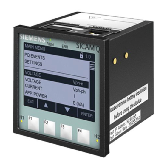
Introduction 1.3 Device Design Device Design Mechanical Design The device is designed for panel flush-mounting. The electrical modules are installed in a plastic case with the dimensions (W x H x D) 96 mm (3.78 inch) x 96 mm (3.78 inch) x 100 mm (3.94 inch). The front side of the device contains the display, 4 softkeys located under the display, and 4 LEDs. - Page 26 Introduction 1.3 Device Design [le_Q100_rear-side, 1, --_--] Figure 1-2 Layout of SICAM Q100 – Rear Side Serial interface J (RS485) LEDs Terminal block U for Binary inputs Terminal block G for Binary outputs Terminal block H for power supply Terminal block F for voltage measurement Terminal block E for current measurement (phases I and phase I Terminal block E for current measurement (phase I...
- Page 27 Introduction 1.3 Device Design Display and Softkeys [le_Q100_HMI_front side, 1, --_--] Figure 1-3 Display and Softkeys Title: Show the name of the current display Display: Show parameter settings, measured values, and diagrams Current functions of the softkeys Softkeys: Select screens or settings at the device Terminal Diagram of the Rear Plate [dw_overview_q100, 2, en_US] Figure 1-4...
- Page 28 SICAM, SICAM Q100 7KG95xx, Manual E50417-H1040-C522-A8, Edition 09.2020...
-
Page 29: Device Functions
Device Functions General Information on Measuring and Recording Setting Process Connections and Other Settings Measurement and Evaluation Functions Energy Management Device-Recorder Functions Device Visualization, Evaluation, and Reporting Functions Ethernet Communication Serial Communication Modbus TCP to Modbus RTU Gateway 2.10 Other Device Functions 2.11 System Functions SICAM, SICAM Q100 7KG95xx, Manual... -
Page 30: General Information On Measuring And Recording
Device Functions 2.1 General Information on Measuring and Recording General Information on Measuring and Recording Measuring System 2.1.1 The device measures the power quality according to IEC 61000-4-30 Ed. 3 in 1-phase or polyphase energy supply systems. The basic measuring interval for calculation of the following values is 10 cycles in 50-Hz systems or 12 cycles in 60-Hz systems: •... - Page 31 Device Functions 2.1 General Information on Measuring and Recording Measured Quantities and Operational Measurement Uncertainty acc. to IEC 62586-1 Product Standard Class A and Standards IEC 61000-4-30 Ed. 3, IEC 61000-4-7, and IEC 61000-4-15 Table 2-1 Measured Quantities and their Operational Measurement Uncertainty Operational Measurement Uncertainty acc.
- Page 32 Device Functions 2.1 General Information on Measuring and Recording Operational Measurement Uncertainty acc. to IEC 62586-1 Class A, Measured Quantity Unit Measuring Range IEC 61000-4-30 Ed. 3, IEC 61000-4-7, IEC 61000-4-15 Mains signaling voltage 0 % to 15 % Udin Condition: 3 % to 15 % of Udin (star) / MSV (delta)
-
Page 33: Recording System
Device Functions 2.1 General Information on Measuring and Recording Measured Quantity Unit Rated Value Measuring Range Accuracy Class Active energy WP – 1 % to 200 % I rated + demand, - supply Reactive energy WQ varh – 2 % to 200 % I rated inductive, capacitive Apparent energy WS... -
Page 34: Measurands
Device Functions 2.1 General Information on Measuring and Recording Recording Measurands Storage Interval/Storage Application Method Magnitude of current 10 min (30 s, 1 min, 10 min, Long-time monitoring of 15 min, 30 min, 1 h, 2 h) current- and power-related Current harmonics and inter- values harmonics... - Page 35 Device Functions 2.1 General Information on Measuring and Recording 4-Wire 4-Wire Network Network 3-Wire 3-Wire 3-Wire 4-Wire (Star) (Star) Network Network Network Network Measured Quan- 1-Phase (Delta) (Delta) (Delta) (Star) Circuit Unbal- Unbal- tity System anced (3I) anced (3I) Balanced Unbal- Unbal- Balanced...
-
Page 36: Harmonics, Interharmonics, And Emissions Depending On The Connection Types
Device Functions 2.1 General Information on Measuring and Recording 4-Wire 4-Wire Network Network 3-Wire 3-Wire 3-Wire 4-Wire (Star) (Star) Network Network Network Network Measured Quan- 1-Phase (Delta) (Delta) (Delta) (Star) Circuit Unbal- Unbal- tity System anced (3I) anced (3I) Balanced Unbal- Unbal- Balanced... - Page 37 Device Functions 2.1 General Information on Measuring and Recording 4-Wire 4-Wire Measured Network Network 3-Wire 3-Wire 3-Wire 4-Wire Quantity (Star) (Star) Network Network Network Network (x = 1 to 63, 1-Phase (Delta) (Delta) (Delta) (Star) Circuit Unbal- Unbal- System y = 1 to 49) anced (3I) anced (3I) (Balanced...
- Page 38 Device Functions 2.1 General Information on Measuring and Recording 4-Wire 4-Wire Measured Network Network 3-Wire 3-Wire 3-Wire 4-Wire Quantity (Star) (Star) Network Network Network Network (x = 1 to 63, 1-Phase (Delta) (Delta) (Delta) (Star) Circuit Unbal- Unbal- System y = 1 to 49) anced (3I) anced (3I) (Balanced...
-
Page 39: Measured Quantities Of Power Depending On The Connection Types
Device Functions 2.1 General Information on Measuring and Recording 2.1.3.3 Measured Quantities of Power Depending on the Connection Types Table 2-6 Measured Quantities of Power Depending on the Connection Types in Power Systems 4-Wire 4-Wire Network Network 3-Wire 3-Wire 3-Wire 4-Wire (Star) (Star) -
Page 40: Measured Quantities Of Energy Depending On Connection Types
Device Functions 2.1 General Information on Measuring and Recording 4-Wire 4-Wire Network Network 3-Wire 3-Wire 3-Wire 4-Wire (Star) (Star) Network Network Network Network Measured 1-Phase (Delta) (Delta) (Delta) (Star) Circuit Unbal- Unbal- Quantity System anced (3I) anced (3I) (Balanced Unbal- Unbal- Balanced (1I) -
Page 41: Flicker Depending On Connection Types
Device Functions 2.1 General Information on Measuring and Recording 4-Wire 4-Wire Network Network 3-Wire 3-Wire 3-Wire 4-Wire (Star) (Star) Network Network Network Network Measured 1-Phase (Delta) (Delta) (Delta) (Star) Circuit Unbal- Unbal- Quantity System anced (3I) anced (3I) (Balanced Unbal- Unbal- Balanced (1I) - Page 42 Device Functions 2.1 General Information on Measuring and Recording 4-Wire 4-Wire Network Network 3-Wire 3-Wire 3-Wire 4-Wire (Star) (Star) Network Network Network Network Measured 1-Phase (Delta) (Delta) (Delta) (Star) Circuit Unbal- Unbalanced Quantity System anced (3I) (3I) (Balanced Unbal- Unbal- Balanced (1I) anced (3I)
-
Page 43: Setting Process Connections And Other Settings
Device Functions 2.2 Setting Process Connections and Other Settings Setting Process Connections and Other Settings General 2.2.1 Before taking measurements, make sure to configure the settings in the Configure tab according to the topology of your device. Select the favored process connections or other settings in the navigation window of the Configure tab to see and change the set parameters. - Page 44 Device Functions 2.2 Setting Process Connections and Other Settings [sc_q100_ac_measurement, 1, en_US] Figure 2-1 Configure Tab, AC Measurement, Basic Settings • Configure the respective parameters according to the following table. NOTE When configuring values ensure that they do not contradict each other. Table 2-9 Settings for AC Measurement Parameter...
- Page 45 Device Functions 2.2 Setting Process Connections and Other Settings Parameter Default Setting Setting Range Nominal/Declared supply AC 230.00 V AC 57.73 V to 400 V (autorange) voltage IEC 61000-4-30 Class A: • Up to AC 230 V: 200 % overvoltage •...
-
Page 46: Configuration Via Display
Device Functions 2.2 Setting Process Connections and Other Settings NOTE The following voltages must be in the same range: • Operating voltage • Primary rated voltage of the voltage transformer • Nominal/declared supply voltage • After the parameterization, click Send. •... -
Page 47: Binary Inputs
Device Functions 2.2 Setting Process Connections and Other Settings Parameter Default Setting Setting Range Use PTs: PT primary AC 10 000 V AC 100.0 V to 1 000 000.0 V Use PTs: PT secondary AC 100 V AC 1.0 V to 460.0 V Prim. -
Page 48: Configuration And Evaluation Via User Interface
Device Functions 2.2 Setting Process Connections and Other Settings 2.2.3.2 Configuration and Evaluation via User Interface Parameterization Binary Inputs [sc_q100_BI_configuration_tab, 1, en_US] Figure 2-3 Configure Tab, Binary Inputs (Detail) To change the binary input settings in the Configure tab, proceed as follows: •... -
Page 49: Configuration And Evaluation Via Display
Device Functions 2.2 Setting Process Connections and Other Settings Parameter Default Setting Setting Range Software filtering time 1 (* 2 ms) 2 ms to 120 000 ms (only settable if Routed as: is (settable in 2-ms increments) set to Status information) Source inverted Add entry to operational log (only settable if Routed as: is... -
Page 50: Binary Outputs
Device Functions 2.2 Setting Process Connections and Other Settings Binary Outputs 2.2.4 2.2.4.1 Function Description The device has 2 binary outputs. Binary outputs are issued as indications. 4 Operating modes are possible: • Persistent • Persistent with fail safe • Pulse •... - Page 51 Device Functions 2.2 Setting Process Connections and Other Settings Pulse This indication is output as pulse. If the indication changes again while the output pulse is ON, the pulse output time is not restarted. This means that a change of the indication during the pulse output will be ignored.
-
Page 52: Configuration And Evaluation Via User Interface
Device Functions 2.2 Setting Process Connections and Other Settings 2.2.4.2 Configuration and Evaluation via User Interface Parameterization Binary Outputs (Relay Outputs) To change the binary output settings in the Configure tab, proceed as follows: • In the navigation window, select Operational parameters → Process connections and click Binary outputs. -
Page 53: Configuration And Evaluation Via Display
Device Functions 2.2 Setting Process Connections and Other Settings Parameter Default Setting Setting Range Source Type Energy Counter -none- Acc. to list box Energy counter Energy increase per pulse 1.00 Wh 0.10 Wh/VAh/varh to 1 000 000.00 Wh/VAh/varh Output time for pulse operating 20 * 10 ms = 200 ms 50 ms to 3 600 000 ms mode... -
Page 54: Leds
Device Functions 2.2 Setting Process Connections and Other Settings LEDs 2.2.5 2.2.5.1 Function Description Behavior of the LEDs [dw_LED-output, 1, en_US] Figure 2-13 Behavior of the LEDs 2.2.5.2 Configuration via User Interface Parameterization of the LEDs To change the LED settings in the Configure tab, proceed as follows: •... - Page 55 Device Functions 2.2 Setting Process Connections and Other Settings Table 2-13 Settings for LEDs Parameter Default Setting Setting Range Device ready Not settable ERROR -none- Errors are signaled as parameterized (only error indications can be parameterized). -none- Battery failure Ethernet link error Time synchronization error Primary NTP server error Secondary NTP server...
-
Page 56: Device And Language
Device Functions 2.2 Setting Process Connections and Other Settings Device and Language 2.2.6 2.2.6.1 Configuration via User Interface Parameterization Device and Language To configure the Device name, Language and Date/time format in the Configure tab, proceed as follows: • In the navigation window, select Administrative and click Device and language. [sc_device_and_language, 2, en_US] Figure 2-15 Configure Tab, Device and Language... - Page 57 Device Functions 2.2 Setting Process Connections and Other Settings Parameterization User Language Preselection NOTE The user language can be preset, for example when starting the user interface for the first time. DEUTSCH is set by default. To configure the User language preselection in the Configure tab, proceed as follows: •...
-
Page 58: Configuration Via Display
Device Functions 2.2 Setting Process Connections and Other Settings NOTE If you change the user language, the device will restart after pressing the Send button and subsequently activating the settings. [sc_language_restart, 1, en_US] Figure 2-17 Restart Information • After a successful restart, connect to the device again. •... -
Page 59: Date/Time
Device Functions 2.2 Setting Process Connections and Other Settings The following interface displays are available: [dw_display_language_regional, 1, en_US] Figure 2-19 Language/Regional [dw_display_language, 1, en_US] Figure 2-20 Language 2.2.7 Date/Time 2.2.7.1 Configuration via User Interface Setting Date/Time To change the date/time settings in the Maintenance tab, proceed as follows: •... -
Page 60: Configuration Via Display
Device Functions 2.2 Setting Process Connections and Other Settings Setting the Date and Time Manually (24-hour format) • Enter the desired time into the fields Day (format dd), Month (format mm), Year (format yyyy), Hour (format hh), and Minute (format mm). •... - Page 61 Device Functions 2.2 Setting Process Connections and Other Settings [sc_q100_wind_farm, 1, en_US] Figure 2-23 Maintenance Tab, Wind Farm Mode • Select yes to activate the Wind Farm mode. Select no to deactivate the Wind Farm mode. If you activate the Wind Farm mode, the device restarts and only the functions for the wind farm are avail- able.
-
Page 62: Measurement And Evaluation Functions
Device Functions 2.3 Measurement and Evaluation Functions Measurement and Evaluation Functions AC Operational Values 2.3.1 2.3.1.1 Function Description Following AC operational values are gathered during measurement and shown both on the user interface and numerically on the display. • Voltage magnitudes Va, Vb, Vc, Vab, Vbc, Vca •... -
Page 63: Configuration And Evaluation Via Display
Device Functions 2.3 Measurement and Evaluation Functions [sc_evaluation_ac_values, 4, en_US] Figure 2-24 Value View and Evaluation Tab for AC Operational Values (Detail) NOTE If *** is displayed instead of a value, this value is invalid. If ^^^ is displayed instead of a value, this value is in overflow. 2.3.1.3 Configuration and Evaluation via Display Submenu Various Measured Quantities... -
Page 64: Harmonics, Interharmonics, Direction Harmonics
Device Functions 2.3 Measurement and Evaluation Functions [dw_ac_power, 1, en_US] Figure 2-25 Submenu Various Measured Quantities Harmonics, Interharmonics, Direction Harmonics 2.3.2 2.3.2.1 Function Description Harmonic Power and Harmonic Angles Measurement of phase angles is helpful to analyze different phenomena. It can be used for the following purposes: •... - Page 65 Device Functions 2.3 Measurement and Evaluation Functions [dw_harmonic directions, 1, en_US] Figure 2-26 Principle of Harmonic Directions For measuring the RMS values and the phase angles, a 10-cycle interval is used for 50-Hz distribution systems. For 60-Hz distribution systems, a 12-cycle interval is used. For the active power of the aggregated harmonics, the following factors are used to caluculate the direction: •...
- Page 66 NOTE You can find further information about this feature in the application notes https://new.siemens.com/ global/en/products/energy/energy-automation-and-smart-grid/power-quality-measurement.html → Down- loads → SICAM Q200/SICAM Q100 → Other Sales Information → Application Notes → document: Applica- tion Note Harmonic Phase Angles Direction.
-
Page 67: Configuration And Evaluation Via User Interface
Device Functions 2.3 Measurement and Evaluation Functions Measured Quantity Measurement Recorder Measurement Recorder Measurement Recorder (x = 1 to 50, Max. Value Min. Value y = 1 to 49) PQDIF, CSV PQDIF, CSV PQDIF, CSV x = 1: Fundamental H_Vbc-x –... - Page 68 Device Functions 2.3 Measurement and Evaluation Functions [sc_q100_harmonics voltage, 1, en_US] Figure 2-28 Value View and Evaluation Tab for Voltage Harmonics • Configure the parameter in the list box according to the following table: Table 2-17 Setting for Evaluation of Voltage Harmonics Parameter Default Setting Setting Options...
- Page 69 Device Functions 2.3 Measurement and Evaluation Functions View in Diagrams: [sc_q100_harmonics voltage_diagram, 1, en_US] Figure 2-29 Value View and Evaluation Tab for Voltage Harmonics, Diagram View in Tables: [sc_q100_harmonics voltage_table, 1, en_US] Figure 2-30 Value View and Evaluation Tab for Voltage Harmonics, Instantaneous Values, Table SICAM, SICAM Q100 7KG95xx, Manual E50417-H1040-C522-A8, Edition 09.2020...
- Page 70 Device Functions 2.3 Measurement and Evaluation Functions [sc_q100_harmonics voltage_max, 1, en_US] Figure 2-31 Value View and Evaluation Tab for Voltage Harmonics, Maximum Values, Table Evaluation Harmonic Currents, THDS, TDD, and K-Factor To display the measured values in the Value view and evaluation tab, proceed as follows: •...
- Page 71 Device Functions 2.3 Measurement and Evaluation Functions Table 2-18 Setting for Evaluation of Harmonic Currents Parameter Default Setting Setting Options Measurement output Diagram Table Diagram • Click Display. The detailed results are displayed in tables or in diagrams. The instantaneous values and the maximum values are both presented.
- Page 72 Device Functions 2.3 Measurement and Evaluation Functions View in Tables: [sc_Harmonics current by table ins., 1, en_US] Figure 2-34 Value View and Evaluation Tab for Harmonic Currents, Instantaneous Values, Table [sc_view harmonic currents table max., 1, en_US] Figure 2-35 Value View and Evaluation Tab for Harmonic Currents, Maximum Values, Table Evaluation Harmonics Power To display the measured values in the Value view and evaluation tab, proceed as follows: •...
- Page 73 Device Functions 2.3 Measurement and Evaluation Functions [sc_harmonic power, instantaneous, 1, en_US] Figure 2-36 Value View and Evaluation Tab for the Harmonic Power, Instantaneous Value The harmonics power function supports to hide harmonics that you are not interested in from the display table.
- Page 74 Device Functions 2.3 Measurement and Evaluation Functions [sc_harmonics power direction, 1, en_US] Figure 2-37 Value View and Evaluation Tab for the Harmonics Power Direction, Aggregated Value The harmonics power function supports to hide harmonics that you are not interested in from the display table.
- Page 75 Device Functions 2.3 Measurement and Evaluation Functions [sc_q100_interhamonics voltage, 1, en_US] Figure 2-38 Value View and Evaluation Tab for Voltage Interharmonics • Configure the parameter in the list box according to the following table: Table 2-19 Setting for Evaluation of Voltage Interharmonics Parameter Default Setting Setting Options...
- Page 76 Device Functions 2.3 Measurement and Evaluation Functions View in Tables: [sc_q100_interhamonics voltage_table, 1, en_US] Figure 2-40 Value View and Evaluation Tab for Voltage Interharmonics, Instantaneous Values, Table [sc_view harmonic currents table max., 1, en_US] Figure 2-41 Value View and Evaluation Tab for Voltage Interharmonics, Maximum Values, Table Evaluation of Interharmonic Currents, THDS, TDD, and K-Factor To display the measured values in the Value view and evaluation tab, proceed as follows: •...
- Page 77 Device Functions 2.3 Measurement and Evaluation Functions [sc_interharmonic currents, 1, en_US] Figure 2-42 Value View and Evaluation Tab for Interharmonic Currents • Configure the parameter in the list box according to the following table: Table 2-20 Setting for Evaluation of Interharmonic Currents Parameter Default Setting Setting Options...
- Page 78 Device Functions 2.3 Measurement and Evaluation Functions View in Diagrams: [sc_interharmonic currents_diagram, 1, en_US] Figure 2-43 Value View and Evaluation Tab for Interharmonic Currents, Diagram SICAM, SICAM Q100 7KG95xx, Manual E50417-H1040-C522-A8, Edition 09.2020...
- Page 79 Device Functions 2.3 Measurement and Evaluation Functions View in Tables: [sc_interharmonic currents_table_instantaneous, 1, en_US] Figure 2-44 Value View and Evaluation Tab for Interharmonic Currents, Instantaneous Values, Table SICAM, SICAM Q100 7KG95xx, Manual E50417-H1040-C522-A8, Edition 09.2020...
-
Page 80: Configuration And Evaluation Via Display
Device Functions 2.3 Measurement and Evaluation Functions [sc_interharmonic current_table_max, 1, en_US] Figure 2-45 Value View and Evaluation Tab for Interharmonic Currents, Maximum Values, Table 2.3.2.3 Configuration and Evaluation via Display Submenu Voltage Harmonics V and Current Harmonics I (Bar Charts) [dw_submenu_evaluation_harmonics_Q100, 1, en_US] Figure 2-46 Submenu Harmonic Voltage and Harmonic Current... -
Page 81: Ac Power And Energy
Device Functions 2.3 Measurement and Evaluation Functions Submenu THDS [dw_submenu_THDS2_Q100, 1, en_US] Figure 2-47 Submenu THDS V and THDS I AC Power and Energy 2.3.3 2.3.3.1 Function Description Following AC power and energy values are gathered during measurement and shown both on the user inter- face and numerically on the display: •... -
Page 82: Configuration And Evaluation Via Display
Device Functions 2.3 Measurement and Evaluation Functions [sc_q100_AC power and energy, 1, en_US] Figure 2-48 Evaluation AC Power and Energy NOTE If *** is displayed instead of a value, this value is invalid. If ^^^ is displayed instead of a value, this value is in overflow. 2.3.3.3 Configuration and Evaluation via Display Submenu Various Measured Quantities... -
Page 83: Reset Energy Counters
Device Functions 2.3 Measurement and Evaluation Functions [dw_measured quantities, 1, en_US] Figure 2-49 Submenu Various Measured Quantities Submenu Active Energy [dw_active_energy, 2, en_US] Figure 2-50 Submenu Active Energy Submenu Reactive Energy [dw_reactive_energy, 1, en_US] Figure 2-51 Submenu Reactive Energy Submenu Apparent Energy [dw_apparent_energy, 1, en_US] Figure 2-52 Submenu Apparent Energy... -
Page 84: Voltage Events
Device Functions 2.3 Measurement and Evaluation Functions [sc_Reset energy counters, 2, en_US] Figure 2-53 Maintenance Tab, Reset Energy Counters • Click Reset energy counters. The load profile buffer is deleted. The Action was successful indication is displayed on the status bar. NOTE Executing this action will reset the following values: •... -
Page 85: Configuration And Evaluation Via User Interface
Device Functions 2.3 Measurement and Evaluation Functions NOTE Currently SICAM PQS ignores the voltage event log section in a PQDIF file. To read the logs, you can use 3rd party tools such as PQDiffractor. 2.3.4.2 Configuration and Evaluation via User Interface Parameterization Event Recorders To configure the Voltage event values in the Configure tab, proceed as follows: •... - Page 86 Device Functions 2.3 Measurement and Evaluation Functions • Configure the respective parameters according to the following table. Table 2-22 Settings for Voltage Events Parameter Default Setting Setting Range Voltage Event 110 % 105 % to 140 %, increments of 5 % Swell threshold 90 % 75 % to 95 %, increments of 5 %...
- Page 87 Device Functions 2.3 Measurement and Evaluation Functions [sc_event_evalu, 3, en_US] Figure 2-55 Value View and Evaluation Tab for Events NOTE The duration format is xx.xx.xxx s. In the figure you see the last 3 numbers in ms. • Configure the respective parameters according to the following table. Table 2-23 Settings for Evaluation of Events Parameter...
-
Page 88: Evaluation Via Display
Device Functions 2.3 Measurement and Evaluation Functions Parameter Default Setting Setting Range End time Current date/time You can edit the text box directly or select the end time from the calendar. Measurement output Table Table • Select one of the following Measured-value output options: –... - Page 89 Device Functions 2.3 Measurement and Evaluation Functions [dw_submenu_voltage_events, 1, en_US] Figure 2-56 Evaluation PQ Events The following interface displays are available: [dw_display_PQ_events, 1, en_US] Figure 2-57 PQ Events [dw_q100_display_dip, 1, en_US] Figure 2-58 List of PQ Events [dw_q100_display_swell, 1, en_US] Figure 2-59 Analysis of PQ Events SICAM, SICAM Q100 7KG95xx, Manual...
-
Page 90: Rvc Events
Device Functions 2.3 Measurement and Evaluation Functions RVC Events 2.3.5 2.3.5.1 Function Description Rapid voltage change (RVC) is a quick transition in RMS voltage occurring between 2 steady-state conditions, and during which the RMS voltage does not exceed the dip/swell threshold. The threshold of RVC detection is from 1 % up to 6 % of Udin. - Page 91 Device Functions 2.3 Measurement and Evaluation Functions [sc_Q100_RVC_configure, 1, en_US] Figure 2-61 Configure Tab, RVC Event • Configure the respective parameters according to the following table. SICAM, SICAM Q100 7KG95xx, Manual E50417-H1040-C522-A8, Edition 09.2020...
- Page 92 Device Functions 2.3 Measurement and Evaluation Functions Table 2-24 Settings for RVC Events Parameter Default Settings Setting Range RVC threshold 1 %, 2 %, 3 %, 4 %, 5 %, 6 % 0.5 %, 1 %, 1.5 %, 2 %, 2.5 %, 3 % RVC hysteresis Event detection mode ph-N...
-
Page 93: Flicker
Device Functions 2.3 Measurement and Evaluation Functions • Select one of the following Measurement output options: – Table If you select Table, click Display. Dependent on the selection, the determined results are displayed in a table. In the multi-page tables, you can show the forward and backward pages with the >> and << buttons. If you want to view a certain page, enter the page number at the bottom and click show. -
Page 94: Configuration And Evaluation Via User Interface
Siemens specifies the working range of the classifier as 0.2 ≤ k ≤ 10. The corresponding value P within ± 5 % or ± 0.05 of the factor k, depending on which value is greater. - Page 95 Device Functions 2.3 Measurement and Evaluation Functions • Select a Flicker lamp model according to the following table. The Flicker lamp model selection depends on the Nominal/Declared supply voltage, because flicker is a visual phenomenon created by voltage variations, and the voltage variations are caused by changing in luminance of lighting systems.
- Page 96 Device Functions 2.3 Measurement and Evaluation Functions [sc_evaluation_flicker, 2, en_US] Figure 2-64 Value View and Evaluation in AC Operational Values Tab To display the Flicker values in the Value view and evaluation tab, proceed as follows: • In the navigation window, select Evaluation and data management and click Records. SICAM, SICAM Q100 7KG95xx, Manual E50417-H1040-C522-A8, Edition 09.2020...
-
Page 97: Evaluation Via Display
2.5.2.2 Configuration and Evaluation via User Interface. The user interface requires the SIGRA Plug-in. For more information on the SIGRA plug-in, contact the Siemens Hotline. – If you select CSV, click Download. The measured values are downloaded as a CSV file and are exported to the storage location you selected. - Page 98 Device Functions 2.3 Measurement and Evaluation Functions [dw_submenu_flicker_display, 1, en_US] Figure 2-66 Evaluation Flicker The following interface displays are available: [dw_display_short_flicker, 1, en_US] Figure 2-67 Short Flicker [dw_display_long_flicker, 1, en_US] Figure 2-68 Long Flicker SICAM, SICAM Q100 7KG95xx, Manual E50417-H1040-C522-A8, Edition 09.2020...
-
Page 99: Energy Management
Device Functions 2.4 Energy Management Energy Management Load Profile 2.4.1 2.4.1.1 Function Description General The load profile reflects the history of the electric power and documents the distribution of power fluctuations and peaks. The load profile is determined on the basis of 10/12 cycles (50 Hz/60 Hz) and saved as average value at the end of a measuring period in the load-profile image. - Page 100 Device Functions 2.4 Energy Management Methods of Load-Profile Determination The device supports the following load-profile determination methods: • Fixed block • Rolling block Fixed Block The Fixed-block method is characterized by the number of subperiods per period that is set to 1. It means the period length is equal to the length of the subperiod.
- Page 101 Device Functions 2.4 Energy Management The following figure shows the history of the measuring periods during the load-profile determination: [dw_load-profile-rolling-block, 1, en_US] Figure 2-71 History of the Measuring Periods for Determination of the Load Profile according to the Rolling-Block Method Load-Profile Data at the Communication Interface The following load-profile data are available during a measuring period: •...
- Page 102 Device Functions 2.4 Energy Management Historical Load-Profile Data The device records the following measurands: Table 2-29 Historical Load-Profile Data Measurement Cumulated Power Arithmetic Average Maximum Values Minimum Values Values Power Values ±x ±x Import Export ±x ±x Import Export Storage of Load-Profile Data The load-profile data are stored in a ring buffer with up to 4000 datasets.
- Page 103 Device Functions 2.4 Energy Management If the set length of the subperiods in the device does not correspond to the length in the telegram, the synchronization pulse is ignored. Load-profile data are still recorded though based on the internal clock of the device.
-
Page 104: Configuration And Evaluation Via User Interface
Device Functions 2.4 Energy Management The additional information is stored with the other load-profile data and can be retrieved via the communica- tion interfaces. 2.4.1.2 Configuration and Evaluation via User Interface Parameterization the Load Profile To change the load profile settings in the Configure tab, proceed as follows: •... - Page 105 Device Functions 2.4 Energy Management Parameter Default Setting Setting Range Synchronization source Internal clock None Protocol Binary input 1 to 2 Internal clock Kind of used reactive power Qtot NOTE Changing the number and length of the subperiods deletes the load-profile buffer. If a binary input is used as synchronization source, its properties must be configured (see chapter 2.2.3.2 Configuration and Evaluation via User Interface.
- Page 106 Device Functions 2.4 Energy Management [sc_Load_profile_evaluation, 4, en_US] Figure 2-73 Value View and Evaluation Tab for Load Profile In the decimal separator, you can select whether you want to display the load-profile data with comma or decimal point after the download. To download the load profile, proceed as follows: •...
-
Page 107: Configuration Via Display
Device Functions 2.4 Energy Management File download → Save • In the dialog File download, click Save. The Save in dialog opens. • Select the file path. • Use the file name suggested in the list box or assign a new file name with the file extension .csv. •... -
Page 108: Maintenance - Presets
Device Functions 2.4 Energy Management Table 2-31 Settings for Load Profile Parameter Default Setting Setting Range Subperiod time 15 min 1 min to 6 min in 1-min steps, 10 min, 12 min, 15 min, 20 min, 30 min, 60 min No. -
Page 109: Configuration And Evaluation Via User Interface
Device Functions 2.4 Energy Management Time Stamp of Export kWh Import kVARh Import Export kVARh kVAh the Last Period 2019-03-15 14.04164982 2.154378414 6737.519043 6737.519043 00:00:00 2019-03-15 12.24571609 1.000230339 6674.347168 6674.347168 00:15:00 2019-03-15 11.24571609 3.000230339 6674.347168 6674.347168 00:30:00 If the energy profile is enabled, the load profile is set to a fixed configuration as follows: •... -
Page 110: Tariffs
Device Functions 2.4 Energy Management • Configure the respective parameters according to the following table. Table 2-32 Settings for Energy Profile Parameter Default Setting Setting Range Enable energy profile Interval 15 min 15 min 30 min 45 min 24 h •... -
Page 111: Configuration And Evaluation Via User Interface
Device Functions 2.4 Energy Management 2.4.3.2 Configuration and Evaluation via User Interface Parameterization Tariffs To change the Tariff values in the Configure tab, proceed as follows: • In the navigation window, select Energy management and click Tariffs (TOU). [sc_tariffs_configure, 1, en_US] Figure 2-77 Tariffs (TOU) Configuration •... - Page 112 Device Functions 2.4 Energy Management Parameter Default Setting Setting Range Season x (x = 1 or 2) Tariff y (y Every Day Every Day = 1 to 8) Workday/ Weekend Workday Selection Weekend Coverage Check Pass Fail (with gap) Fail (with overlap) •...
- Page 113 Device Functions 2.4 Energy Management [sc_tariff_calendar, 1, en_US] Figure 2-78 Configure Tab, Synchronization Source: Calendar, Pass SICAM, SICAM Q100 7KG95xx, Manual E50417-H1040-C522-A8, Edition 09.2020...
- Page 114 Device Functions 2.4 Energy Management [sc_calendar fail with words, 1, en_US] Figure 2-79 Configure Tab, Synchronization Source: Calendar, Fail with Gap or Overlap Evaluation You can determine 8 tariffs for all energy types. To display the Tariff values in the Value view and evaluation tab, proceed as follows: SICAM, SICAM Q100 7KG95xx, Manual E50417-H1040-C522-A8, Edition 09.2020...
-
Page 115: Energy Upper Limit
Device Functions 2.4 Energy Management • In the navigation window, select Operational parameters → Process connections and click Tariffs (TOU). [sc_Q100_tariffs_evaluation, 1, en_US] Figure 2-80 Value View and Evaluation Tab for Tariffs (TOU) After data transmission, the values are further processed in the peripheral devices. NOTE To reset the tariff values see chapter 2.3.3.4 Reset Energy... -
Page 116: Energy Freeze And Reset
Device Functions 2.4 Energy Management Table 2-34 Settings for Energy Upper Limit Parameter Default Setting Setting Range Energy Upper Limit Energy Counter Energy Counter Energy Value • After the parameterization, click Send. • In the navigation window, select Finish configuration and click Activation. Energy Freeze and Reset 2.4.5 2.4.5.1... -
Page 117: Co2 Emissions
Device Functions 2.4 Energy Management [sc_q100_frozen energy, 1, en_US] Figure 2-83 Value View and Evaluation Tab for Frozen Energy CO2 Emissions 2.4.6 2.4.6.1 Function Description The device supports to calculate and show the CO emissions. The calculation is based on the accumulated imported and exported active energy, and the configured CO emission factor. - Page 118 Device Functions 2.4 Energy Management Table 2-36 Settings for CO Emissions Parameter Default Setting Setting Range emission calculation active No emission factor 0.000 g CO /kWh 0.000 g CO /kWh to 1 000 000.000 g CO /kWh • After the parameterization, click Send. •...
-
Page 119: Reset Co Emission Values
Device Functions 2.4 Energy Management [sc_q100_AC power and energy, 1, en_US] Figure 2-86 Value View and Evaluation Tab, AC Power and Energy If the CO emission calculation is deactivated, the columns for CO emissions are not shown in the table of AC Power and Energy or in the table of Frozen Energy. -
Page 120: Device-Recorder Functions
Device Functions 2.5 Device-Recorder Functions Device-Recorder Functions Start and Stop of Recorders 2.5.1 2.5.1.1 Configuration via User Interface Parameterization Recorders - Start/Stop To change the start and stop of recorders settings in the Configure tab, proceed as follows: • In the navigation window, select Recording and reporting and click Recorders - Start/Stop [sc_q100_recording parameters, 1, en_US] Figure 2-87 Configure Tab, Recorders - Start/Stop... -
Page 121: Measurement Recorder
Device Functions 2.5 Device-Recorder Functions • If you want to stop the recording, click Stop recording and execute the activation. The Recording status field shows the entry Not running and Start recording is displayed on the user interface. NOTE The restart of the record is carried out after a power failure automatically. The status will change from Not running to Running when you change and activate parameters. - Page 122 Device Functions 2.5 Device-Recorder Functions [sc_freq_meas_2min, 1, en_US] Figure 2-88 Example 1 for Measurement Recorder, Frequency Measurement of 10 Seconds, and Record Duration of 2 Minutes [sc_freq_meas_20min, 1, en_US] Figure 2-89 Example 2 for Measurement Recorder, Frequency Measurement of 10 Seconds, and Record Duration of 1 Hour Recording and Evaluation of the Measured Quantities NOTE...
- Page 123 Device Functions 2.5 Device-Recorder Functions Table 2-38 Recording and Evaluation of the Measured Quantities Max. Value Min. Value Measured Quantities PQDIF, CSV Frequency 10 s freq – – (fixed 10 s freq.) (system frequency based on 10/12 cycles) (system frequency based on 10 s) Vavg –...
-
Page 124: Configuration And Evaluation Via User Interface
Device Functions 2.5 Device-Recorder Functions Max. Value Min. Value Measured Quantities PQDIF, CSV Power Factor Phase Angle φUIa φUIb φUIc φUI φab V – – φbc V – – φca V – – φab I – – φbc I – –... - Page 125 Device Functions 2.5 Device-Recorder Functions [sc_q100_recorder parameters_measurement, 1, en_US] Figure 2-90 Configure Tab, Recorder Parameters Input/Output Window NOTE The voltage is recorded in the following network types: • 3P4W (3 phases/4 wires): phase-to-phase voltage or phase-to-ground voltage • 3P3W (3 phases/3 wires): only phase-to-phase voltage •...
- Page 126 Device Functions 2.5 Device-Recorder Functions Parameter Default Setting Setting Range Harmonics parity Even File generation every: 24 h At average interval: File generation every: (corresponds to the setting of 30 s 1 h (fix) the Average interval parameter) 1 min 2 h (fix) The created PQDIF files can be 10 min, 15 min, 30...
- Page 127 Device Functions 2.5 Device-Recorder Functions • Configure the respective parameters in the list boxes according to the following tables. Table 2-40 Settings for Evaluation Measurement Recorder Parameter Default Setting Setting Range Record type Measurement recorder Trend Recorder Measurement recorder Measurement Recorder Start time Current time Any with calendar function Time format:...
-
Page 128: Reset Min/Max Values
If you select Diagram, click Display. You can view 1-day or 1-week records with a diagram. The user interface requires the SIGRA Plug-in. For more information on the SIGRA plug-in, contact the Siemens Hotline. – If you select CSV, click Download. - Page 129 Device Functions 2.5 Device-Recorder Functions Table 2-41 Triggers of the Waveform Recorder Trigger Source Measurement Time Trigger Conditions Base Voltage trigger 1/2 cycle The trigger starts if one of the following conditions is met: • The measured value > the upper threshold •...
- Page 130 Device Functions 2.5 Device-Recorder Functions [dw_q100_Waveform_example, 1, en_US] Figure 2-93 Example of Waveform Recording The following table shows which measured quantities can be recorded in COMTRADE files when a corre- sponding trigger function is activated and the channel is selected in Recorder routing. Table 2-42 Recording and Evaluation Recorder Routing...
-
Page 131: Configuration And Evaluation Via User Interface
Device Functions 2.5 Device-Recorder Functions Recorder Routing Measured Quantities COMTRADE Binary input Binary Input 1 Binary Input 2 Frequency 10/12 cycle frequency RMS value The frequency channel records the RMS value, the binary-input channel records the status value, and other analog channels record sampled values. - Page 132 Device Functions 2.5 Device-Recorder Functions [sc_q100_trigger management, 2, en_US] Figure 2-94 Configure Tab, Trigger Management • Configure the respective parameters according to the following table. SICAM, SICAM Q100 7KG95xx, Manual E50417-H1040-C522-A8, Edition 09.2020...
- Page 133 Device Functions 2.5 Device-Recorder Functions Table 2-43 Settings for Trigger Management Parameter Default Setting Setting Range Voltage trigger limits Trigger active Voltage event User-defined Voltage event Tolerance unit Percentage Percentage Numerical Lower threshold 90.00 % of the nominal/declared supply 0.00 % to 99.99 % of the nominal/ voltage declared supply voltage 0.0 V to 1 000 000.0 V...
-
Page 134: Trend Recorder
2.10.2 File Transfer. During the download progress, the selected files are stored by the browser. You can use the software SIGRA to display the transmitted record data. For more information on SIGRA, contact the Siemens Hotline. Trend Recorder 2.5.4 2.5.4.1... -
Page 135: Configuration And Evaluation Via User Interface
Device Functions 2.5 Device-Recorder Functions Table 2-44 Recording and Evaluation Measured Quantities PQDIF • Interfaces: protocols IEC 61850, HTML • Conditions: 1/2 cycle, RMS values 2.5.4.2 Configuration and Evaluation via User Interface Parameterization Trend Recorder To configure the Trend recorder values in the Configure tab, proceed as follows: •... - Page 136 Device Functions 2.5 Device-Recorder Functions NOTE The voltage is recorded in the following connection types: 3P4W (3-phase/4-wire): phase-to-phase voltage and phase-to-ground voltage 3P3W (3-phase/3-wire): only phase-to-phase voltage • After the parameterization, click Send. • In the navigation window, select Finish configuration and click Activation. File Generation of Trend Recorder The Trend recorder values can be displayed on the Web server and can be saved as PQDIF files.
-
Page 137: Event Recorder
If you select Diagram, click Display. You can view 1-day or 1-week records with a diagram. The user interface requires the SIGRA Plug-in. For more information on the SIGRA plug-in, contact the Siemens Hotline. – If you select CSV, click Download. -
Page 138: Reset Pq Events
Device Functions 2.5 Device-Recorder Functions Table 2-47 Recording and Evaluation Measured Quantities Values • Interfaces: protocols IEC 61850 and Modbus TCP, HTML, display determining overvoltage, undervoltage and voltage interruption according to EN 50160, for example. 2.5.5.2 Reset PQ Events You can reset the following PQ events: •... -
Page 139: Mains Signaling Voltage (Msv)
Device Functions 2.5 Device-Recorder Functions Mains Signaling Voltage (MSV) 2.5.6 2.5.6.1 Function Description Mains signaling voltage (MSV) measurement is performed according to IEC 61000-4-30. The device detects mains signaling frequencies from 100 Hz to 3 kHz. The threshold for detection and capture is from 1 % up to 15 % of Un. - Page 140 Device Functions 2.5 Device-Recorder Functions Table 2-48 Settings for Mains Signaling Voltage Parameter Default Setting Setting Range Mains Signaling Voltage Measurement MSV active No. of MSV frequencies 1 frequency 1 frequency 2 frequencies Frequency 1 216.60 Hz 100.00 Hz to 3000.00 Hz Frequency 2 1060.00 Hz 100.00 Hz to 3000.00 Hz...
-
Page 141: Transient Detection
– Diagram You can view 1-day or 1-week records with a diagram. The user interface requires the SIGRA Plug-in. For more information on the SIGRA plug-in, contact the Siemens Hotline. • Click Display Transient Detection 2.5.7... - Page 142 Device Functions 2.5 Device-Recorder Functions [dw_transient-detection, 1, en_US] Figure 2-101 Transient Detection A transient will be detected if the instantanious value of the voltage (measured as sample) is higher than a given voltage reference level. Once the detected sample is higher than the voltage reference level the end of the transient is detected when the sample value is lower than the reference value minus 8 % of the reference value.
-
Page 143: Configuration And Evaluation Via User Interface
Device Functions 2.5 Device-Recorder Functions 2.5.7.2 Configuration and Evaluation via User Interface Parameterization Transient Detection To change the parameters of Transient detection in the Configure tab, proceed as follows: • In the navigation window, select Recording and reporting and click Transient detection. [sc_q100_transient detection, 1, en_US] Figure 2-102 Configure Tab, Transient Detection... -
Page 144: Memory Management
Device Functions 2.5 Device-Recorder Functions NOTE The last 255 transient events are displayed; older transient events are deleted automatically. Memory Management 2.5.8 2.5.8.1 Function Description In the device, the SD card follows the Industrial Grade level with a memory size of 2 GB. The memory manage- ment is used to distribute the memory size for each record type. - Page 145 Device Functions 2.5 Device-Recorder Functions • Configure the respective parameters in the list boxes according to the following table. If you update the percentage of any record type, the estimation data is changed with a certain ratio, and vice versa. Table 2-51 Settings for Memory Management Parameter...
-
Page 146: Formatting Sd Card
Device Functions 2.5 Device-Recorder Functions [sc_q100_memory_evalu, 1, en_US] Figure 2-105 Value View and Evaluation Tab, Memory Management 2.5.8.3 Formatting SD Card If you want to format the SD card, proceed as follows: • In the navigation window, select Maintenance and click Format SD card. [sc_maintenance_sd_card, 2, en_US] Figure 2-106 Maintenance Tab, Format SD Card... -
Page 147: Device Visualization, Evaluation, And Reporting Functions
Device Functions 2.6 Device Visualization, Evaluation, and Reporting Functions Device Visualization, Evaluation, and Reporting Functions Power Quality Reporting Functions 2.6.1 2.6.1.1 Function Description The device generates a Power Quality Report (PQ report) automatically or manually. According to the standard EN 50160, the device generates the report by analyzing the measurand including power frequency, supply voltage magnitude, flicker, voltage unbalance, harmonics, and events (CBEMA/ITIC curve). - Page 148 Device Functions 2.6 Device Visualization, Evaluation, and Reporting Functions [sc_q100_report configuration, 1, en_US] Figure 2-107 Configure Tab, Report Configuration • Configure the respective parameters according to the following table. For the General information, you can edit the text box directly. SICAM, SICAM Q100 7KG95xx, Manual E50417-H1040-C522-A8, Edition 09.2020...
- Page 149 Device Functions 2.6 Device Visualization, Evaluation, and Reporting Functions Table 2-52 Settings for Report Configuration Parameter Default Setting Setting Options Power Quality Report • Evaluation mode according to EN 50160 LV&MV EN 50160 LV&MV • EN 50160 HV • User-defined Flagging acc.
-
Page 150: Itic/Cbema Curve
Device Functions 2.6 Device Visualization, Evaluation, and Reporting Functions Evaluation To display the values in the Value view and evaluation tab, proceed as follows: • In the navigation window, select Evaluation and data management and click Power Quality report. [sc_q200_PQ_Report_evalu, 1, en_US] Figure 2-108 Value View and Evaluation Tab for PQ Report •... -
Page 151: Evaluation Via User Interface
Device Functions 2.6 Device Visualization, Evaluation, and Reporting Functions [dw_ITIC curve, 1, en_US] Figure 2-109 ITIC Curve 2.6.2.2 Evaluation via User Interface To display the ITIC/CBEMA curve in the Value view and evaluation tab, proceed as follows: • In the navigation window, select Evaluation and data management and click Power Quality report. •... - Page 152 Device Functions 2.6 Device Visualization, Evaluation, and Reporting Functions NOTE The device generates ITIC/CBEMA curves to the PQ report only if voltage events are detected. SICAM, SICAM Q100 7KG95xx, Manual E50417-H1040-C522-A8, Edition 09.2020...
-
Page 153: Ethernet Communication
Device Functions 2.7 Ethernet Communication Ethernet Communication Ethernet 2.7.1 2.7.1.1 Function Description The device has a 100Base-T Ethernet port (RJ45 connectors) at the top side of the device. The Ethernet port can be configured to be an Ethernet network with 1 MAC and 1 IP address. 2.7.1.2 Configuration via User Interface Parameterization Communication Ethernet... -
Page 154: Configuration Via Display
Device Functions 2.7 Ethernet Communication Parameter Default Setting Setting Range Enable SNMP Bus protocol Modbus TCP -None- Modbus TCP IEC 61850 Both NOTE If you select Both for Bus protocol, Modbus TCP and IEC 61850 work in parallel. • After the parameterization, click Send. •... - Page 155 Device Functions 2.7 Ethernet Communication [sc_q100__Modbus_TCP_settings, 1, en_US] Figure 2-113 Configuration Tab, Modbus TCP Settings • Configure the respective parameters according to the following table. Table 2-54 Settings for Modbus TCP Parameter Default Setting Setting Range Standard port number Not settable Access rights Full Full...
-
Page 156: Configuration Via Display
Device Functions 2.7 Ethernet Communication Parameter Default Setting Setting Range Keep alive time 10 s 0 s = switch off 1 s to 65 535 s Communication supervision 600 (* 100 ms) 0 s = none time 100 ms to 6 553 400 ms NOTE The 3 port numbers must be different from each other. - Page 157 Device Functions 2.7 Ethernet Communication [sc_q100__Diagnosis_Modbus-TCP, 1, en_US] Figure 2-115 Maintenance Tab, Diagnosis Modbus TCP • To clear the counters for Modbus TCP, click Clear counters. All counters for Modbus TCP are reset to 0. Diagnostic Information for Standard Server and User-Port Server •...
-
Page 158: Iec 61850
Device Functions 2.7 Ethernet Communication • Access rights: as configured • Communication supervision time: as configured Diagnostic Information of Connections • Server port: Server port number of the current connection in the respective column; if 0 is displayed, the connection is inactive or down •... - Page 159 Device Functions 2.7 Ethernet Communication [sc_q100_IEC61850_configuration, 2, en_US] Figure 2-116 Configuration Tab, IEC 61850 Settings • Configure the respective parameters according to the following table. Table 2-55 Settings for IEC 61850 Parameter Default Setting Setting Range IED Name SICAM_Q100_01 Any, max. 60 characters Only a-z, A-Z, _, 0-9 are permitted.
-
Page 160: Configuration Via Display
Device Functions 2.7 Ethernet Communication Parameter Default Setting Setting Range Frequency - Dead band 0.05 % 0.02 % 0.05 % 0.2 % Angle - Dead band 0.5 % 0.2 % 0.5 % • After the parameterization, click Send. • In the navigation window, select the Finish configuration menu and click Activation. Download IID File The Instantiated IED Description (IID) file contains the data of the currently parameterized network type, for example: 4-wire, any load (3P4W), the currently parameterized IP address(es), subnet mask(s), default... - Page 161 Device Functions 2.7 Ethernet Communication For the diagnosis of the protocol IEC 61850 in the Maintenance tab, proceed as follows: • In the navigation window, select Diagnosis and click IEC 61850. [sc_q100_IEC61850_diagnosis, 1, en_US] Figure 2-118 Maintenance Tab, Diagnosis IEC 61850 Parameter With IEC 61850, the following parameters are displayed: •...
-
Page 162: Ethernet Security
The secure HTTPS protocol is used for access to Internet sites of the device. Internally, the device uses the open source library OpenSSL for the encrypted communication. For certificate handling in your browser, follow the instructions from the Application Note. You can find this Application Note on the Internet site https://w3.siemens.com/smartgrid/global/en/products-systems-solutions/ cyber-security/Pages/products.aspx under Downloads > Application Notes. SNMPv3 You can find a detailed description of functions and conditions for SNMPv3 in chapter 3.7 Simple Network... - Page 163 Device Functions 2.7 Ethernet Communication Table 2-56 Settings for SNMPv3 Settings Default Setting Setting Range User name Empty, Up to 32 characters (User name for SNMPv3 access) for example: not set • Numbers 0 to 9 • Small and capital Latin letters •...
- Page 164 Device Functions 2.7 Ethernet Communication [sc_SNMP-MIB-file-download, 1, en_US] Figure 2-120 File Download Dialog Box • Click Save. The Save As dialog opens and you can save the SICAM Q.mib file in any folder and use it in an MIB browser. SICAM, SICAM Q100 7KG95xx, Manual E50417-H1040-C522-A8, Edition 09.2020...
-
Page 165: Serial Communication
Device Functions 2.8 Serial Communication Serial Communication Modbus RTU Slave 2.8.1 2.8.1.1 Function Description The serial communication using Modbus RTU (slave) with the device is executed via the RS485 interface. 2.8.1.2 Configuration via User Interface Parameterization Serial Communication with Modbus RTU (Slave) via RS485 Interface Precondition: The Modbus RTU protocol must have been activated for the RS485 interface. -
Page 166: Configuration Via Display
Device Functions 2.8 Serial Communication Parameter Default Setting Setting Range Parity Even None, 1 stop bit Even None, 2 spot bit Access rights Full Full Read only Communication supervision 600 * 100 ms 0 s = none time 100 ms to 6 553 400 ms Response delay 0 ms 0 ms to 1000 ms... -
Page 167: Diagnosis Modbus Rtu Slave
Device Functions 2.8 Serial Communication Parameter Default Setting Setting Range Parity Even None, 1 stop bit Even None, 2 spot bit Access rights Full Full Read only Communication supervision 600 * 100 ms 0 s = none time 100 ms to 6 553 400 ms Response delay 0 ms 0 ms to 1000 ms... -
Page 168: Modbus Rtu Master
Device Functions 2.8 Serial Communication • Framing errors: Number of detected frame errors (invalid stop bit, for example if the baud rate is wrong) • Parity errors: Number of detected parity errors (wrong parity) Serial Server • Good messages: Total number of messages received that were detected as valid Modbus messages •... -
Page 169: Configuration Via User Interface
Device Functions 2.8 Serial Communication Schematic Overview of the Functioning of the Modbus RTU Master [dw_function-gateway-q100, 1, en_US] Figure 2-124 Functioning of the Modbus RTU Master 2.8.2.2 Configuration via User Interface Parameterization Serial Communication with Modbus RTU Master via RS485 Interface Precondition: The Modbus RTU Master protocol must have been activated for the RS485 interface. - Page 170 Device Functions 2.8 Serial Communication To change the Modbus RTU Master settings in the Configure tab, proceed as follows: • In the navigation window, select Administrative, click Communication serial, and select Modbus RTU master as the Bus protocol. [sc_ Q100_configure_Modbus_RTU_Master_US, 1, en_US] Figure 2-125 Configuration Tab, Modbus RTU Master •...
-
Page 171: Configuration Via Display
Device Functions 2.8 Serial Communication Parameter Default Settings Setting Range Additional inter-character 1 ms 0 ms to 100 ms timeout The Modbus specification requires that the indi- vidual characters of a serial Modbus RTU tele- gram have to be transmitted successively with a maximum character gap of 1.5 character times (or max. -
Page 172: Diagnosis Modbus Rtu Master
Device Functions 2.8 Serial Communication Table 2-60 Settings for Communication Serial Parameter Default Settings Setting Range Bus protocol -none- -none- Modbus RTU (slave) Modbus RTU master Baud rate 19 200 bit/s 1200 bit/s, 2400 bit/s 4800 bit/s, 9600 bit/s 19 200 bit/s, 38 400 bit/s 57 600 bit/s, 115 200 bit/s Parity Even... - Page 173 Device Functions 2.8 Serial Communication The diagnosis of the Modbus RTU master provides the following information: • Check of the state of the serial communication with telegram and error counters and an overview of the set serial interface parameters. • Overview of request telegrams sent by the Modbus RTU master including request status for every tele- gram.
- Page 174 Device Functions 2.8 Serial Communication Request Telegrams Table 2-62 Description of the Parameters in the Request Telegrams Parameter Description Status Status of the request messages • Good: correct response • Not requested: the request was not sent yet after changing the configuration •...
-
Page 175: Modbus Slave Devices
Device Functions 2.8 Serial Communication Parameter Description Data type Data type requested with this request message (one or more data objects of this data type were requested; different data types are always requested with separate messages, because they have different scan cycles). - Page 176 Device Functions 2.8 Serial Communication [sc_Config Modbus slave devices, 1, en_US] Figure 2-128 Configure Tab, Modbus Slave Devices, Device 1 Activated • Configure the respective parameters according to the following table. Table 2-63 Settings for Modbus Slave Device 1 Parameter Default Setting Setting Range Name...
- Page 177 Device Functions 2.8 Serial Communication Parameter Default Setting Setting Range Scan cycle on error 1 to 3600 s (1 s to 1 h) Retry cycle for sending request telegrams if the retry limits are exceeded or in the case of error responses.
- Page 178 Device Functions 2.8 Serial Communication [sc_Q100_Modbus_slave devices_configuration, 1, en_US] Figure 2-129 Configure Tab, Modbus Slave Device 1, Measured Value Mapping • Configure the respective parameters according to the following table. SICAM, SICAM Q100 7KG95xx, Manual E50417-H1040-C522-A8, Edition 09.2020...
- Page 179 Device Functions 2.8 Serial Communication Table 2-64 Settings for Assignment of the Measured Values of the Modbus Slave Device 1 Parameter Default Setting Setting Range Name MV x Slv 1 Max. 31 characters (x = 1 to 15) Max. 10 characters if the name is also to be displayed on the device display.
- Page 180 Device Functions 2.8 Serial Communication Table 2-65 Data Format on Bus Data Format on Bus Description Setting Range Invalid Recognition Used by (Example) Float32 IEEE Float value NaN = invalid SENTRON PAC3x00, to +10 (2 registers) INF = overflow SICAM AI 7XV5674, SICAM T 7KG966, SICAM P50 7KG775 Int16...
- Page 181 Device Functions 2.8 Serial Communication [sc_q100_Modbus_slave_devices_indication, 1, en_US] Figure 2-130 Configure Tab, Modbus Slave Device 1, Indication Mapping • Configure the respective parameters according to the following table. Table 2-66 Settings for Assignment of the Indications of the Modbus Slave Device 1 Parameter Default Setting Setting Range...
- Page 182 Device Functions 2.8 Serial Communication Parameter Default Setting Setting Range Register number 1 to 65 535 Bit offset 0 to 15 (for data format 1 Bit) (only relevant for register types 0 to 31 (for data format 1 Bit in UInt32) Input register or Holding register) Table 2-67...
- Page 183 Device Functions 2.8 Serial Communication File download → Open Alternatively, you can view the information on the screen and print it if needed. Proceed as follows: • In the File download dialog, click Open. A text editor opens which contains the mapping information on the Modbus slave device (CLIENT MAPPING INFORMATION).
- Page 184 Device Functions 2.8 Serial Communication [sc_Modbus_slave_indication_mappig, 3, en_US] Figure 2-132 Configuration of 3 indications (Example) [sc_client-mapping-info, 1, en_US] Figure 2-133 Resulting CLIENT MAPPING INFORMATION (Example) Table 2-68 Description and Setting Ranges of the Parameters in the Text File Label Measurand (MV) Description Setting Range Indication (I)
- Page 185 Device Functions 2.8 Serial Communication Label Measurand (MV) Description Setting Range Indication (I) MV, I Register type 0x0 – Coil status register 0x1 – Input status register 0x3 – Input register 0x4 – Holding register Bit offset 0 to 15 (for FT = 1BIT) (for INDICATION in Holding 0 to 31 (for FM = 1BITI- registers)
- Page 186 Device Functions 2.8 Serial Communication • In the navigation window, select Administrative, click Modbus slave devices 1-4, activate the Modbus slave device 1, and click Import. [sc_Modbus_RTU_master_import, 4, en_US] Figure 2-134 Configure Tab, Modbus Slave Device, Import • Click Browse..The File Download dialog opens.
- Page 187 Device Functions 2.8 Serial Communication Viewing Measured Values and Indications • In the Information column (see figure Figure 2-135), click View values: NOTE The button is not enabled if the status shows deactivated and no mapping data. [sc_M-S-values view, 1, en_US] Figure 2-136 Value View and Evaluation Tab, View Values and Indications Measured values and indications are displayed for the respective Modbus slave device.
-
Page 188: Modbus Tcp To Modbus Rtu Gateway
Device Functions 2.9 Modbus TCP to Modbus RTU Gateway Modbus TCP to Modbus RTU Gateway Function Description 2.9.1 Modbus TCP to Modbus RTU Gateway Function The device supports the function of Modbus TCP to Modbus RTU gateway. SICAM, SICAM Q100 7KG95xx, Manual E50417-H1040-C522-A8, Edition 09.2020... - Page 189 Device Functions 2.9 Modbus TCP to Modbus RTU Gateway Schematic Overview of Modbus TCP to Modbus RTU Gateway [dw_function-master-gateway-q100, 1, en_US] Figure 2-137 Functioning of Modbus TCP to Modbus RTU Gateway NOTE During a firmware update of the the device, the Modbus gateway function is stopped. SICAM, SICAM Q100 7KG95xx, Manual E50417-H1040-C522-A8, Edition 09.2020...
-
Page 190: Configuration Via User Interface
Device Functions 2.9 Modbus TCP to Modbus RTU Gateway Configuration via User Interface 2.9.2 Parameterization Modbus TCP to Modbus RTU Gateway Precondition: The Modbus TCP protocol must have been activated for at least one Ethernet interface. The Modbus RTU Master protocol must have been selected under serial communication. To change the settings of the Modbus TCP/Modbus RTU Gateway in the Configure tab, proceed as follows: •... - Page 191 Device Functions 2.9 Modbus TCP to Modbus RTU Gateway [sc_Modbus-TCP-RTU-gateway_Q100, 2, en_US] Figure 2-138 Configure Tab, Modbus TCP to Modbus RTU Gateway Settings • Configure the respective parameters according to the following table. SICAM, SICAM Q100 7KG95xx, Manual E50417-H1040-C522-A8, Edition 09.2020...
- Page 192 Device Functions 2.9 Modbus TCP to Modbus RTU Gateway Table 2-70 Settings for Modbus TCP/RTU Gateway Parameter Default Settings Setting Range Activated Unit ID of this device 1 to 255 0 to 10 Retry limit 10 (* 10 ms) (1 to 6000) * 10 ms = 10 ms to 60 s Response timeout The following figure shows the flow chart of parameterization.
-
Page 193: Configuration And Evaluation Via Display
Device Functions 2.9 Modbus TCP to Modbus RTU Gateway Configure: Mapping – Measured values (chapter 2.8.3.2 Configuration and Evaluation via User Interface) Configure: Mapping – Indications (chapter 2.8.3.2 Configuration and Evaluation via User Inter- face) Configure: Mapping – Import (chapter 2.8.3.2 Configuration and Evaluation via User Interface) Configure: Mapping –... - Page 194 Device Functions 2.9 Modbus TCP to Modbus RTU Gateway Table 2-71 Description of the Parameters in Last TCP/RTU Gateway Messages Parameter Description Status Status of the request messages • Good: correct response • No response: the bus device does not respond (for example, communication failure) •...
-
Page 195: Other Device Functions
Device Functions 2.10 Other Device Functions 2.10 Other Device Functions Message Logs 2.10.1 2.10.1.1 Function Description Operational Log The Operational log is shown in the Information tab (see chapter 4.13.2.7 Starting the User Interface during Operation) and in the Maintenance tab. It can be deleted in the Maintenance tab (see chapter 2.10.1.2 View and Clear Message Logs). - Page 196 Device Functions 2.10 Other Device Functions [sc_Delete op logs, 2, en_US] Figure 2-141 Maintenance Tab, Delete Operational Log • Click Delete log. All operational indications are deleted without backup. The indication no. 00001 appears in the log list: Clear Operational Log. NOTE If you need the operational indications, for example for subsequent analysis, save or print them out.
- Page 197 Device Functions 2.10 Other Device Functions View and Clear the Error Logs To delete the error logs in the Maintenance tab, proceed as follows: • In the navigation window, select Message logs and click Error log. • Click Delete log. All error logs are deleted without backup.
-
Page 198: File Transfer
Device Functions 2.10 Other Device Functions NOTE If you need the error messages, for example for subsequent analysis, save or print them out. File Transfer 2.10.2 2.10.2.1 Function Description The device provides the file download function. You can download the data in a standard format from the File transfer window. -
Page 199: Single File Download
Click Download. During the download progress, the selected files are stored in the specified directory. You can use the SIGRA software to display the transmitted recorder data. Contact the Siemens Hotline for more informa- tion, see the chapter Preface. The File Download dialog opens. You can save or open the download file. -
Page 200: Multiple File Download Via Internet Explorer
Device Functions 2.10 Other Device Functions [sc_file_dow_dia, 1, en_US] Figure 2-145 File Download Dialog NOTE The button Download is displayed only when the Record list is available. • Click each file link. The browser indicates you to save the file to a selected path. 2.10.2.4 Multiple File Download via Internet Explorer Preparation... - Page 201 Device Functions 2.10 Other Device Functions Adding the IP Address of Your Device into the Trusted Sites • Open the Internet Explorer, for example, Internet Explorer 11, and select Tools → Internet Options. • In the Security tab, select Trusted sites and click Sites. [sc_multiple download_sites, 1, en_US] Figure 2-146 Sites...
- Page 202 Device Functions 2.10 Other Device Functions • Enter the IP address of your device and click Add. Ensure that the IP address of your device is added in the Websites list box. [sc_multiple download_trusted sites, 1, en_US] Figure 2-147 Trusted Sites NOTE Mark the check box of Require server verification (https:) for all sites in this zone.
- Page 203 Device Functions 2.10 Other Device Functions • Enable 2 options, the Access data sources across domains and the Initialize and script ActiveX controls not marked as safe for scripting. [sc_security_settings, 2, en_US] Figure 2-148 Changing Security Settings – Miscellaneous SICAM, SICAM Q100 7KG95xx, Manual E50417-H1040-C522-A8, Edition 09.2020...
- Page 204 Device Functions 2.10 Other Device Functions [sc_Security_settings_trusted_site_zone, 3, en_US] Figure 2-149 Changing Security Settings – ActiveX Controls and Plug-Ins • Click OK. Updating the System Registry • Click the Start menu on the desktop. • Enter regedit.exe in the Search box. •...
- Page 205 Device Functions 2.10 Other Device Functions • Navigate to in the directory: HKEY_LOCAL_MACHINE\SOFTWARE\Microsoft\Internet Explorer\ActiveX Compatibility\{00000566-0000-0010-8000-00AA006D2EA4}\Compatibility Flags. [sc_Registry_editor, 3, en_US] Figure 2-150 Updated Registry • Double-click Compatibility Flags and set the Value data to 0. [sc_Value_data, 3, en_US] Figure 2-151 Changing the Compatibility Flag Value •...
- Page 206 Device Functions 2.10 Other Device Functions [sc_Trusted_site_adding, 3, en_US] Figure 2-152 Example of New Keys • Close the Registry Editor. Ensure that the check box of Enable Protected Mode (requires restarting Internet Explorer) in Trusted sites is unmarked. [sc_protected mode_disabled, 1, en_US] Figure 2-153 Protected Mode SICAM, SICAM Q100 7KG95xx, Manual...
- Page 207 Device Functions 2.10 Other Device Functions Downloading Multiple Files NOTE The Record List of Multiple File Download with Internet Explorer is identical for trend recorder, measure- ment recorder and waveform recorder. To do a multiple file download, execute the same steps as for the single file download, but select the down- load type Multiple file download and proceed further as follows: •...
-
Page 208: Multiple File Download Via Chrome
SIGRAPlugin: HTML data of the event recorder and the recorder values on the recorder page • PQDiffractor: PQDIF files For more information on the programs, contact the Siemens Hotline. Multiple File Download via Chrome 2.10.2.5 The screenshots related with Chrome in this chapter are taken from Chrome V71.0.3578.98 (Official Build) (64‑bit). - Page 209 Device Functions 2.10 Other Device Functions • Start Google Chrome. • Click Customize and control Google Chrome → Settings. [sc_Chrome_settings, 3, en_US] Figure 2-156 Chrome Settings SICAM, SICAM Q100 7KG95xx, Manual E50417-H1040-C522-A8, Edition 09.2020...
- Page 210 Device Functions 2.10 Other Device Functions • Click Show advanced settings…. [sc_Chrome_settings_advanced, 3, en_US] Figure 2-157 Advanced Settings SICAM, SICAM Q100 7KG95xx, Manual E50417-H1040-C522-A8, Edition 09.2020...
- Page 211 Device Functions 2.10 Other Device Functions • Click Change… to select the path for saving the download file. Do not select the Ask where to save each file before downloading. [sc_Chrome_settings_downloads, 3, en_US] Figure 2-158 Change Path for Download Files •...
-
Page 212: Multiple File Download Via Firefox
Device Functions 2.10 Other Device Functions If you select the Multiple file download as a download type, proceed as follows: • Select the multiple files in the Record list. [sc_download_multi_file, 1, en_US] Figure 2-159 Value View and Evaluation Tab, Download Multiple Files (for Example Trend Recorder) •... - Page 213 Device Functions 2.10 Other Device Functions • Change the security settings. [sc_Troubleshooting, 2, en_US] Figure 2-160 Troubleshooting Information SICAM, SICAM Q100 7KG95xx, Manual E50417-H1040-C522-A8, Edition 09.2020...
- Page 214 Device Functions 2.10 Other Device Functions • Click Show Folder. [sc_Show_folder, 2, en_US] Figure 2-161 Show Folder • Open the mimeTypes.rdf file with the Text Editor in the opened folder. • Add the following content to the mimeTypes.rdf file and save it. [sc_add_contents, 1, en_US] Figure 2-162 Add New Contents...
- Page 215 Device Functions 2.10 Other Device Functions Selecting Path via Firefox • Click Tools → Options. [sc_options_Firefox, 2, en_US] Figure 2-163 Select Options • Click Browse… to select the path for saving the download file. SICAM, SICAM Q100 7KG95xx, Manual E50417-H1040-C522-A8, Edition 09.2020...
-
Page 216: Time Synchronization
Device Functions 2.10 Other Device Functions [sc_Firefox_select_path, 2, en_US] Figure 2-164 Select Path • Click OK. Downloading Multiple Files Refer to Downloading Multiple Files, Page 211. Time Synchronization 2.10.3 2.10.3.1 Function Description General During operation, the device needs the date and time for all time-relevant processes. The term time is used throughout this section to refer to both the date and the time. - Page 217 Device Functions 2.10 Other Device Functions Internal Time Keeping Time Format The internal time is kept in UTC (Universal Time Coordinated) from 01.01.2000, 00:00 to 31.12.2099, 23:59. To display the local time, for example on the HTML pages, you can configure a local time correction factor and the automatic adjustment to daylight saving time during parameterization.
-
Page 218: Configuration Via User Interface
Modbus RTU using the RS485 interface. The time information can also be transmitted from the systems control via Modbus TCP or IEC 61850 using Ethernet interfaces. When using the Ethernet connection, Siemens recommends to synchronize the device from an NTP server. - Page 219 Device Functions 2.10 Other Device Functions [sc_admin_Time_sync, 1, en_US] Figure 2-165 Configure Tab, Time Synchronization • Configure the respective parameters according to the following table. Table 2-74 Settings for Time Synchronization Parameter Default Setting Setting Range Source time synchronization Internal Internal Ethernet NTP Fieldbus...
- Page 220 Device Functions 2.10 Other Device Functions Parameter Default Setting Setting Range Start of DST March January to December Last week First week Second week Third week Fourth week Last week Sunday Sunday to Saturday 2:00 AM 12:00 AM to 11:00 PM (in increments of 1 h) End of DST October...
- Page 221 Device Functions 2.10 Other Device Functions [sc_q100_maint._sntp_menu, 1, en_US] Figure 2-166 SNTP Menu, Maintenance To view the SNTP diagnosis in the Maintenance tab, proceed as follows: • In the navigation window, select Diagnosis and click SNTP. SICAM, SICAM Q100 7KG95xx, Manual E50417-H1040-C522-A8, Edition 09.2020...
- Page 222 Device Functions 2.10 Other Device Functions [sc_SNTP Diagnosis, 2, en_US] Figure 2-167 Diagnosis, SNTP The following messages are listed in the tables and the meaning of each column is explained here: Parameter Explanation NTP servers general information Serial number Peer IP address of the NTP server configured in the Time synchronization tab Active The NTP server is active or not.
- Page 223 Device Functions 2.10 Other Device Functions NOTE The table of Primary NTP server or Secondary NTP server lists the latest 10 telegrams. The older tele- grams are automatically overwritten. You cannot delete the telegrams manually. If no primary or secondary NTP server is configured (IP address 0.0.0.0 is entered during the time-synchroniza- tion configuration), •...
-
Page 224: Configuration Via Display
Device Functions 2.10 Other Device Functions 2.10.3.3 Configuration via Display Submenu Time Synchronization [dw_submenu_time_synchronization, 1, en_US] Figure 2-169 Submenu Time Synchronization Table 2-75 Settings for Time Synchronization Parameter Default Setting Setting Range Time source internal internal Ethernet NTP Fieldbus Time zone 00:00 -12 to +13 (hours) (in increments of 0.5 h) -
Page 225: Configuration And Evaluation Via User Interface
Device Functions 2.10 Other Device Functions Hysteresis of the Limiting-Value Violation [dw_hysteresis, 1, en_US] Figure 2-170 Hysteresis (General Representation) 2.10.4.2 Configuration and Evaluation via User Interface Parameterization Limits To change the limit settings in the Configure tab, proceed as follows: •... -
Page 226: Configuration And Evaluation Via Display
Device Functions 2.10 Other Device Functions Parameter Default Setting Setting Range Limit type Lower Lower Upper Hysteresis (%) 1.00 0.00 to 10.00 Violation indication Limit Violation x The name of the indication is customizable; max. 31 characters. (x = 1 to 16) •... -
Page 227: Group Indications
Device Functions 2.10 Other Device Functions Parameter Default Setting Setting Range Value 0.00 -1 000 000 000.00 to +1 000 000 000.00 (unit) Reset hysteresis 1.0 % 0.0 % to 10.0 % State OFF (O) Acc. to the current configuration 2.10.5 Group Indications 2.10.5.1... -
Page 228: Configuration And Evaluation Via User Interface
Device Functions 2.10 Other Device Functions [dw_q200_regular_2x_1, 1, en_US] Figure 2-175 Example: Linking 2 Indications to a Group Indication Rule for Linking Binary Inputs to a Group Indication For a group indication that is used to trigger the waveform recorder, you must select binary inputs or indica- tion groups which are linked by binary inputs as Source and set Source inverted to no for each source. - Page 229 Device Functions 2.10 Other Device Functions [sc_Group_indication_configuration, 3, en_US] Figure 2-177 Configure Tab, Group Indications (Example) • Configure the respective parameters according to the following table. Table 2-78 Settings for Group Indications Parameter Default Setting Setting Range Source -none- Acc. to list box Limit violation, group indication and binary inputs: Only the indications for the...
-
Page 230: Display And Display Settings
Device Functions 2.10 Other Device Functions • After the parameterization, click Send. • In the navigation window, select Finish configuration and click Activation. NOTE Sources are assigned inside a group indication sequentially from source 1 to source 4. If you select -none- at the 1st source in a group indication, you cannot configure further sources in this group indication. - Page 231 Device Functions 2.10 Other Device Functions [sc_display settings, 1, en_US] Figure 2-179 Configure Tab, Display Settings • Configure the respective parameters according to the following table. Table 2-79 Settings for Display Parameter Default Setting Setting Range Contrast 0 to 10 Time until dimmed 0 min to 99 min Refresh time...
- Page 232 Device Functions 2.10 Other Device Functions To configure the User-defined screen values in the Configure tab, proceed as follows: • In the navigation window, select HMI and click User-defined screen. [sc_user-defined_configuration, 1, en_US] Figure 2-180 Configure Tab, User-Defined Screen • Configure the respective parameters in the list boxes according to the following table.
- Page 233 Device Functions 2.10 Other Device Functions Parameter Default Setting Setting Range 2 measured values, numerical: -not assigned- The selection of measured values depends on the network type. • Display 1, numerical Designation can be changed during • Display 2, numerical the parameterization.
-
Page 234: Configuration Via Display
Device Functions 2.10 Other Device Functions 2.10.6.3 Configuration via Display Submenu Display In the main menu, select Settings → Display. [dw_submenu_display, 1, en_US] Figure 2-181 Submenu Display Table 2-81 Settings for Display Parameter Default Setting Setting Range Contrast 0 to 10 Time until dimmed 0 min to 99 min Invert display... - Page 235 Device Functions 2.10 Other Device Functions The following interface displays are available: [dw_display_settings, 1, en_US] Figure 2-182 Display Settings [dw_display_contrast, 1, en_US] Figure 2-183 Display Content User-Defined Screens The user-defined screens are visible on the display only if they were activated via the user interface (see Parameterization User-Defined Screen, Page 231).
-
Page 236: System Functions
[dw_workflow-q100-settings-for-SICAM_PQS, 1, en_US] Figure 2-185 Workflow NOTE You can find more information about SICAM PAS/PQS in the manual SICAM PAS, Overview, order number E50417-X8976-C431-B3 and under http://w3.siemens.com/smartgrid/global/en/products-systems-solutions/ substation-automation/substation-automation/pages/sicam-pas.aspx. Connection with PQ Advisor 2.11.2 Connection with PQ Advisor 2.11.2.1 PQ Advisor Compact The PQ Advisor Compact is a web-based application and can be accessed with a URL. -
Page 237: Firmware Upload
During a firmware update, the device firmware, the default set of parameters, text libraries, HTML files, or parts thereof are updated. NOTE Before updating the firmware, Siemens recommends saving the current parameters set as described in Acti- vating the Set of Parameters, Page 313. - Page 238 Device Functions 2.11 System Functions [sc_q100_upload, 1, en_US] Figure 2-187 Firmware-Upload Indication The Firmware processing dialog opens. [sc_q100__Firmware_processing, 1, en_US] Figure 2-188 Firmware Processing, Firmware Upload • Click Browse... in the section Firmware upload. The Choose file dialog opens. • Select the desired upload file (extension .pck or .cms depending on the current firmware version) in the directory.
- Page 239 Device firmware, default set of parameters, text libraries, HTML files, or parts thereof are uploaded. You can find the upload file in the download area in the Siemens Internet under: https:// support.industry.siemens.com/cs/document/109743592/?en-US. To update the firmware to the latest version, select the following upload file: •...
-
Page 240: Customer Support Functions
It is only necessary to activate these functions via the diagnostic function if you assume the device is not working as expected and you contacted the Siemens Energy Customer Support Center to get additional diagnostic information on the device status. - Page 241 The device provides a fast way to get support from Siemens. To reduce the efforts for getting fast and compre- hensive support, you can collect the relevant data to generate a file by a click and send it to Siemens Energy Customer Support Center via the Secure File Exchange for customer support.
- Page 242 Device Functions 2.11 System Functions [sc_file from one click to customer care, 1, en_US] Figure 2-193 Files Saved from One Click to Customer Care SICAM, SICAM Q100 7KG95xx, Manual E50417-H1040-C522-A8, Edition 09.2020...
-
Page 243: Security
Security Overview Account Management Security Settings Password Management Audit Log Syslog Simple Network Management Protocol v3 (SNMPv3) TCP/UDP Ports Used Customer Support Functions SICAM, SICAM Q100 7KG95xx, Manual E50417-H1040-C522-A8, Edition 09.2020... -
Page 244: Overview
Due to the authentication scheme used by browsers, Siemens cannot provide certificates (for example, during assembly) to be used for HTTPS with browsers. This is because either the... - Page 245 • Deploy in a secured environment only: Siemens recommends protecting network access to its energy automation products with appropriate mechanisms (for example, firewalls, segmentation, VPN). It is advised to configure the environment according to the operational guidelines in order to run the devices in a protected IT environment.
-
Page 246: Account Management
Security 3.2 Account Management Account Management Function Description 3.2.1 The device provides a role-based access control (RBAC) mechanism for the account management. This func- tion is a policy-neutral mechanism for access control to define the roles and privileges. With the RBAC mecha- nism, the permissions to perform certain actions on the device are assigned to specific roles. - Page 247 Security 3.2 Account Management Table 3-2 Access Rights Assigned to Different Roles Role Access to the Web UI Tabs Information Configure Value View and Maintenance Evaluation Guest View all pages Password management – – • Viewer View all operational View all pages View operational log, error logs, settings and diagnosis data...
-
Page 248: Configuration Via User Interface
Security 3.2 Account Management HMI Password The device provides an option to use an HMI password. It determines whether the password for actions at the device display is activated or deactivated. The HMI password is activated by default. • If the HMI password is deactivated, all actions at the device display can be executed without entering a password. - Page 249 Security 3.2 Account Management Parameter Default Setting Setting Range New password Empty 8 to 24 characters Contains at least: Repeat new password • 1 capital Latin letter (A to Z) • 1 small Latin letter (a to z) • 1 digital number (0 to 9) •...
- Page 250 Security 3.2 Account Management [sc_Create_accounts, 3, en_US] Figure 3-4 Configure Tab, Account Management • Click Create local account. SICAM, SICAM Q100 7KG95xx, Manual E50417-H1040-C522-A8, Edition 09.2020...
- Page 251 Security 3.2 Account Management [sc_q100_create_accounts, 1, en_US] Figure 3-5 Configuration Tab, Creating Local Accounts • Create local user accounts according to the following tables. Table 3-4 Settings for Creating Local Accounts Parameter Default Setting Setting Range User name Empty Up to 64 characters New password Empty 8 to 24 characters...
- Page 252 Security 3.2 Account Management Table 3-5 Overview of the Access Rights Assigned to Each Role Description of the Access Rights Role General information viewing Operational data viewing – – – – Configuration settings viewing – – – – Force values –...
- Page 253 Security 3.2 Account Management [sc_account change_delete, 3, en_US] Figure 3-6 Editing or Deleting a Local User Account • Click the icon to edit the password or edit the role of an existing local user account. SICAM, SICAM Q100 7KG95xx, Manual E50417-H1040-C522-A8, Edition 09.2020...
- Page 254 Security 3.2 Account Management [sc_q100_edit_accounts, 1, en_US] Figure 3-7 Editing a Local User Account • Edit the local user account according to the following table. Table 3-6 Settings for Editing a Local User Account Parameters Default Setting Setting Range User name Fixed, not configurable The user name depends on the settings made by the account management.
- Page 255 Security 3.2 Account Management • If you want to delete all the local user accounts, click the button Delete all local user accounts shown in Figure 3-6. As a result, the device restarts automatically. The Log on tab with creating an initial local user account opens after the device restarts, shown in Figure 3-1.
- Page 256 Security 3.2 Account Management [sc_HMI_password, 3, en_US] Figure 3-8 Configuration Tab, HMI Password • Set the HMI password according to the following table. Table 3-7 Settings for HMI Password Parameter Default Setting Setting Range Use HMI password New password Empty 6 digital numbers (0 to 9) Remote Authentication Dial-in User Service (RADIUS Server) The device supports the centralized user-credentials management with a RADIUS server.
- Page 257 Security 3.2 Account Management The RADIUS protocol is deactivated by default. The parameters for the RADIUS server are available and can be configured only after you activate the RADIUS protocol. The device supports 2 RADIUS servers: • Primary RADIUS server •...
- Page 258 Security 3.2 Account Management Table 3-8 Settings for the RADIUS Server Parameter Default Setting Setting Range RADIUS active Primary RADIUS server IP address 0.0.0.0 Port 1812 0 to 65 535 Secret Empty Any (16 to 32 characters) Secondary RADIUS server IP address 0.0.0.0 Port...
-
Page 259: Security Settings
Security 3.3 Security Settings Security Settings Function Description 3.3.1 The device provides the security settings to configure the login settings. NOTE Only a user with the role of administrator or security administrator has the permission to access Security Settings. Security Settings 3.3.2 The user with the account created with a role of administrator or security administrator has the permission to configure the logon security settings. -
Page 260: Password Management
Security 3.4 Password Management Password Management Function Description 3.4.1 To change the Web-UI login password, the device provides the access to Password Management. Configuration via the User Interface 3.4.2 To change the password in the Configure tab, proceed as follows: •... - Page 261 Security 3.4 Password Management • Enter the new password. • Click Confirm. The password is changed. SICAM, SICAM Q100 7KG95xx, Manual E50417-H1040-C522-A8, Edition 09.2020...
-
Page 262: Audit Log
Security 3.5 Audit Log Audit Log Function Description 3.5.1 The device provides an audit log to track the security-relevant events. The audit log can only be viewed by a user with the role Security Auditor or Administrator. The Audit log is located in the Maintenance tab. NOTE The audit log is only available via HTML pages, not via device display. -
Page 263: View Via User Interface
Security 3.5 Audit Log Event Type Description • Configuration access Upload a configuration file • Download a configuration file – Active configuration – Passive configuration Activation of the configuration Activate the configuration change change • Configuration of the CO emis- Activate/deactivate the CO -emission calculation sions... - Page 264 Security 3.5 Audit Log [sc_audit log, 2, en_US] Figure 3-12 Maintenance Tab, Audit Log To update the display of the audit log, click show or press F5 on your keyboard. SICAM, SICAM Q100 7KG95xx, Manual E50417-H1040-C522-A8, Edition 09.2020...
-
Page 265: Syslog
Security 3.6 Syslog Syslog Function Description 3.6.1 In addition to showing audit logs in the Maintenance tab via the user interface, the device supports transmit- ting the audit logs to a central log server using Syslog. Syslog is a well-established internationally implemented standard for message logging. The Syslog standard is specified in the following documents: •... -
Page 266: Configuration Via User Interface
Security 3.6 Syslog Configuration via User Interface 3.6.2 To configure the Syslog function in the Configure tab, proceed as follows: • In the navigation window, select Administrative and click Syslog. [sc_Syslog configure, 2, en_US] Figure 3-13 Configure Tab, Syslog • Configure the respective parameters according to the following table. -
Page 267: View Via Syslog Server
Security 3.6 Syslog View via Syslog Server 3.6.3 If the Syslog function in the device is activated and the Syslog server is running, you can read the audit logs from the Syslog server. The audit logs are sent to the configured Syslog server using the UDP protocol when the logs are recorded in the device. -
Page 268: Simple Network Management Protocol V3 (Snmpv3)
Security 3.7 Simple Network Management Protocol v3 (SNMPv3) Simple Network Management Protocol v3 (SNMPv3) The SNMPv3 security mechanism in the device is also responsible for the RFC3414 (Request for Comments: User-based Security Model (USM)). The following functions and conditions are supported by SNMPv3: •... -
Page 269: Tcp/Udp Ports Used
Security 3.8 TCP/UDP Ports Used TCP/UDP Ports Used Communica- Server/ TCP/UDP Port Activated Description tion Protocol Client by Default HTTPS Server TLS connection to a Web browser for device configuration and value view Client Time synchronization Modbus TCP Server Communication with a station controller using Modbus TCP and Modbus default TCP port Modbus TCP Server... -
Page 270: Customer Support Functions
NOTE For the analysis of a potential problem or malfunction, contact the Siemens Customer Support Center. The following table contains URL addresses that can be used if the Siemens Customer Support Center needs to execute a diagnostic analysis. HTML Page (URL) -
Page 271: Commissioning And First Steps
Commissioning and First Steps Safety Notes Unpacking, Inspecting the Delivery, Installing, and Changing the Battery Assembly Environmental Protection Hints Electrical Connection Communication Connections Binary Connections System Requirements Access Rights 4.10 Meaning of the LEDs 4.11 Commissioning 4.12 Connection Principle 4.13 Operation via PC 4.14 Operation via Display... -
Page 272: Safety Notes
Commissioning and First Steps 4.1 Safety Notes Safety Notes DANGER Hazard due to high voltage Non-observance will lead to death or serious injury. Work may only be carried out by trained personnel who are familiar with and observe the safety require- ments and precautions. -
Page 273: Unpacking, Inspecting The Delivery, Installing, And Changing The Battery
Commissioning and First Steps 4.2 Unpacking, Inspecting the Delivery, Installing, and Changing the Battery Unpacking, Inspecting the Delivery, Installing, and Changing the Battery Unpacking The device has been safely packed for transport in the factory. Unpack the device with care and do not use force. - Page 274 Commissioning and First Steps 4.2 Unpacking, Inspecting the Delivery, Installing, and Changing the Battery To insert the battery, observe the notes in the supplied Product Information and proceed as follows: • Pull out the battery compartment. • Take the battery out of the battery compartment. •...
- Page 275 Commissioning and First Steps 4.2 Unpacking, Inspecting the Delivery, Installing, and Changing the Battery NOTE Battery Disposal The battery used in this device contains lithium. It may only be replaced by qualified personnel and disposed of by authorized recycling companies. Do not dispose of the battery in the regular household waste.
-
Page 276: Assembly
Commissioning and First Steps 4.3 Assembly Assembly General Assembly Notes The device is designed for panel flush-mounting. WARNING Do not touch any live parts. Non-observance may lead to death or serious injury. After installation of the device and wiring, close the control cabinet. ²... - Page 277 Commissioning and First Steps 4.3 Assembly • Insert the device into the assembly opening until it hits the limit and keep holding it tightly. • Attach the 2 mounting elements (included with the device) on both sides of the case. You have the possi- bility to attach the mounting elements as follows: [dw_assembly, 1, en_US] Figure 4-2...
-
Page 278: Environmental Protection Hints
When disposing of or transferring a mobile storage device, Siemens strongly recommends physically destroying it or completely deleting data from the mobile storage device by using a commercially available computer data erasing software. -
Page 279: Electrical Connection
Commissioning and First Steps 4.5 Electrical Connection Electrical Connection [le_Q100_behind_01, 1, --_--] Figure 4-3 Electrical Connection Terminal block H for power supply Terminal block F for voltage measurement Terminal block E for current measurement (phase a and b) Terminal block E for current measurement (phase c and neutral phase N) Terminal block U for binary input Terminal block G for binary output NOTE... - Page 280 Commissioning and First Steps 4.5 Electrical Connection NOTE Always connect the grounding at the device to the terminal for the protective phase grounding (terminal block H). Terminals and Conductors The device has the following terminal blocks: Terminal Block Description 4 inputs for alternating current measurement 4 inputs for alternating voltage measurement Supply voltage 2 binary inputs...
- Page 281 Commissioning and First Steps 4.5 Electrical Connection Assigned Function, Terminal Description Measured Value or Indi- cation U: 1 Binary input 1 Binary input 1 U: 2 Root Common root for both binary inputs U: 3 Binary input 2 Binary input 2 Voltage measuring inputs: In the case of a direct connection and transformer connection, the device has to be safeguarded with a listed 10-A backup fuse or a listed 10-A miniature circuit breaker.
-
Page 282: Communication Connections
Be aware of the safety instruction in chapter 4.1 Safety Notes. If you do not connect cables to the communication connectors, Siemens recommends covering the connec- tors with a cap or dummy plug (not included in the delivery) to prevent the contacts from becoming dirty. Ethernet Interface... - Page 283 Commissioning and First Steps 4.6 Communication Connections Serial Interface (RS485) [le_Q100-behind_02, 2, --_--] Figure 4-5 Communication Interface, Serial Interface Serial Interface J (RS485) The serial Interface J (RS485) is located on the terminal side. Further Technical data see chapter 7.1.3 Communication Interfaces.
-
Page 284: Binary Connections
Commissioning and First Steps 4.7 Binary Connections Binary Connections [le_Q100 binary connection, 1, --_--] Figure 4-6 Binary Connections Binary inputs Binary outputs Terminals and Conductors The device has the following terminal blocks: Terminal Block Description 2 binary inputs 2 binary outputs Terminals for binary inputs/outputs •... -
Page 285: System Requirements
Commissioning and First Steps 4.8 System Requirements System Requirements To operate the device with a PC or notebook, the following system requirements must be met: • PC or notebook with Intel Pentium processor (or compatible type); clock frequency minimum 800 MHz •... -
Page 286: Access Rights
Commissioning and First Steps 4.9 Access Rights Access Rights Access Rights for Configuration, Maintenance, and Updates Access rights are determined by the role types configured in the chapter of 3.2.2 Configuration via User Inter- face. If you are configured as a role of Administrator or User Account manager, you have the full access rights for configuration, maintenance, and updates. -
Page 287: Meaning Of The Leds
Commissioning and First Steps 4.10 Meaning of the LEDs 4.10 Meaning of the LEDs LEDs on the Front Side The device automatically monitors the functions of hardware and software components. The LEDs on the front side of the housing (see Figure 1-1) indicate the current device status. -
Page 288: Commissioning
• Check the polarity and the phase assignment at the instrument transformers. Siemens recommends leaving the device for a minimum of 2 hours in the operating room, before using it to allow temperature equalization and to avoid dimness and condensation. -
Page 289: Web Login/Logout And Password Change
Commissioning and First Steps 4.11 Commissioning • Switch the alternating voltages and alternating currents to be measured at the measurement object on the measuring lines. • Enter the IP address (default: 192.168.0.55) in the web browser. • Enter User name and Password for the Web Login. •... -
Page 290: Changing The Language At Initial Commissioning
Firmware Update at Initial Commissioning NOTE Check the Siemens Internet site whether a new firmware version is available and update your firmware if necessary. You can find the manuals and the firmware via the download area in the Siemens Internet under: http://www.siemens.com/sicam-q100... - Page 291 Commissioning and First Steps 4.11 Commissioning If you want to change the measurement setup, for example by connecting terminals so far unused, proceed analogously to the Initial Commissioning. NOTE If you change the measurement setup, de-energize the supply voltage lines and all measuring lines before opening the control cabinet.
-
Page 292: Connection Principle
Commissioning and First Steps 4.12 Connection Principle 4.12 Connection Principle Using the Device in the Power Systems TT and TN 4.12.1 When using the device in the power systems TT and TN, no special operating conditions must be observed. Standard Application, Examples 4.12.2 The following input wiring diagrams are examples. - Page 293 Commissioning and First Steps 4.12 Connection Principle Example: 3-Wire Network, 2 Voltage Transformers and 1 Current Transformer, Balanced [dw_3-wire-network-balanced, 1, en_US] Figure 4-9 Example: 3-Wire Network, 2 Voltage Transformers and 1 Current Transformer, Balanced NOTICE The secondary voltage on terminal F (voltage) must not exceed AC 600 V (AC 347 V for UL). Non-observance can cause material damage.
- Page 294 Commissioning and First Steps 4.12 Connection Principle Example: 3-Wire Network, Direct Contact at Low-Voltage Power System, 3 Current Transformers, Unbalanced [dw_3-wire-network-without-N, 1, en_US] Figure 4-10 Example: 3-Wire Network, No Voltage Transformer, 3 Current Transformers, Unbalanced Example: 3-Wire Network, No Voltage Transformer, 2 Current Transformers, Unbalanced [dw_3-wire-network-2I-3U, 1, en_US] Figure 4-11 Example: 3-Wire Network, No Voltage Transformer, 2 Current Transformers, Unbalanced...
- Page 295 Commissioning and First Steps 4.12 Connection Principle Example: 3-Wire Network, 2 Voltage Transformers and 2 Current Transformers, Unbalanced [dw_3-wire-network-2x-current, 1, en_US] Figure 4-12 Example: 3-Wire Network, 2 Voltage Transformers and 2 Current Transformers, Unbalanced NOTICE The secondary voltage on terminal F (voltage) must not exceed AC 600 V (AC 347 V for UL). Non-observance can cause material damage.
- Page 296 Commissioning and First Steps 4.12 Connection Principle Example: 3-Wire Network, 2 Voltage Transformers and 3 Current Transformers, Unbalanced [dw_3-wire-network-3x-current, 1, en_US] Figure 4-13 Example: 3-Wire Network, 2 Voltage Transformers and 3 Current Transformers, Unbalanced NOTICE The secondary voltage on terminal F (voltage) must not exceed AC 600 V (AC 347 V for UL). Non-observance can cause material damage.
- Page 297 Commissioning and First Steps 4.12 Connection Principle Example: 4-Wire Network, No Voltage Transformer, 3 Current Transformers, Unbalanced [dw_4-wire-unbal-lowvoltage, 1, en_US] Figure 4-15 Example: 4-Wire Network, No Voltage Transformer, 3 Current Transformers, Unbalanced Example: 4-Wire Network, 3 Voltage Transformers and 3 Current Transformers, Unbalanced [dw_4-wire-unbal-highvoltage, 1, en_US] Figure 4-16 Example: 4-Wire Network, 3 Voltage Transformers and 3 Current Transformers, Unbalanced...
- Page 298 Commissioning and First Steps 4.12 Connection Principle Example: 4-Wire Network, 3 Voltage Transformers and 3 Current Transformers, Unbalanced, Current Transformer at the Neutral Phase [dw_4-wire-unbal-N, 1, en_US] Figure 4-17 Example: 4-Wire Network, 3 Voltage Transformers and 3 Current Transformers, Unbalanced, Current Transformer at the Neutral Phase SICAM, SICAM Q100 7KG95xx, Manual E50417-H1040-C522-A8, Edition 09.2020...
-
Page 299: Special Application, Example
Commissioning and First Steps 4.12 Connection Principle Special Application, Example 4.12.3 Example 3-wire Network, 3 Voltage Transformers and 3 Current Transformers, Unbalanced [dw_3-wire-network-Russia, 1, en_US] Figure 4-18 Example 3-wire Network, 3 Voltage Transformers and 3 Current Transformers, Unbalanced SICAM, SICAM Q100 7KG95xx, Manual E50417-H1040-C522-A8, Edition 09.2020... -
Page 300: Operation Via Pc
Commissioning and First Steps 4.13 Operation via PC 4.13 Operation via PC General Usage Notes 4.13.1 The device can be operated with HTML pages via the connected PC. Additionally, limited operation of the device is possible with softkeys on the display side in connection with the display. The graphical user interface is stored in the device. - Page 301 Commissioning and First Steps 4.13 Operation via PC • Switch on the supply voltage of the device. • Check whether the LEDs indicate that the device is ready (see chapter 5.1.3 LED Indications). • Match the IP address and the subnet mask of the network interface card of your computer to the device settings.
-
Page 302: Enabling Javascript
Commissioning and First Steps 4.13 Operation via PC NOTE When starting the device for the first time, a set of parameters with factory settings is loaded. You can modify these settings during the parameterization. To set a different user language for the user interface, open the Configure tab → Administrative → Device and language and change the language. -
Page 303: Changing The Buffer Mechanism (Only For Microsoft Internet Explorer)
Commissioning and First Steps 4.13 Operation via PC [sc_Internet_options_security, 2, en_US] Figure 4-20 Enabling JavaScript • In the window of the Security tab, select the Internet icon. • On the Security tab set Medium-high. • Click Apply. • Click OK. 4.13.2.3 Changing the Buffer Mechanism (only for Microsoft Internet Explorer) NOTE... -
Page 304: Changing The Security Setting (Only For Microsoft Internet Explorer)
Commissioning and First Steps 4.13 Operation via PC • In the Internet options dialog, open the General tab. • In the dialog of the General tab, select the Settings icon. [sc_website_settings_temporary_internet_files, 2, en_US] Figure 4-21 Changing the Buffer Mechanism • In the Website Data Settings tab, click the Every time I visit the webpage icon. - Page 305 Commissioning and First Steps 4.13 Operation via PC • Enable 2 options, the Access data sources across domains and the Initialize and script ActiveX controls not marked as safe for scripting. [sc_security_settings, 2, en_US] Figure 4-22 Changing Security Settings – Miscellaneous SICAM, SICAM Q100 7KG95xx, Manual E50417-H1040-C522-A8, Edition 09.2020...
-
Page 306: Number Of Connections Via Html
Commissioning and First Steps 4.13 Operation via PC [sc_Security_settings_trusted_site_zone, 3, en_US] Figure 4-23 Changing Security Settings – ActiveX Controls and Plug-Ins • Click OK. NOTE If the Windows system is reinstalled, you must reconfigure the settings related to the Microsoft Internet Explorer. -
Page 307: Layout Of The User Interface
Commissioning and First Steps 4.13 Operation via PC 4.13.2.6 Layout of the User Interface [le_layout_user_interface, 1, en_US] Figure 4-24 Layout of the User Interface Logout icon Online help Active tab (light blue) Inactive tab (dark blue) Navigation bar Button Status bar Dialog window Navigation window 4.13.2.7... - Page 308 Commissioning and First Steps 4.13 Operation via PC NOTE Without user interactions the Web UI will be accessible for 10 minutes (default). You can configure this timeout. The navigation window of the Information tab contains: • Show device information • Operational log Show Device Information •...
-
Page 309: Configuration Of The Device
Commissioning and First Steps 4.13 Operation via PC To show the operational indications, proceed as follows: • In the navigation window, select the Message Logs and click Operational log: [sc_Operational_log, 2, en_US] Figure 4-26 Information Tab, Operational Log NOTE The chapter 2.10.1.2 View and Clear Message Logs explains how to delete the operational indications manually. -
Page 310: Get Device Configuration
Commissioning and First Steps 4.13 Operation via PC [sc_Configure_tab, 2, en_US] Figure 4-27 Configure Tab • Select the Prepare menu in the navigation window and then click either Get device configuration or Open configuration from file. NOTE If you have selected Get device configuration, a copy of the active parameter set of the device is displayed on the screen. -
Page 311: Open Configuration From File
Commissioning and First Steps 4.13 Operation via PC Proceed as follows: [sc_Get_device_configuration, 1, en_US] Figure 4-28 Configure Tab, Get Device Configuration Get Active Configuration and Editing • Click Get active configuration. A copy of the active set of parameters (= active set of parameters) of the device is opened for editing. •... - Page 312 Commissioning and First Steps 4.13 Operation via PC Proceed as follows: [sc_Open-configuration-from-file, 1, en_US] Figure 4-29 Configure Tab, Open Configuration from File • Click Browse..The Choose file dialog opens. [sc_choose-file, 2, en_US] Figure 4-30 Choose File • Select the desired file (extension .cfg) in the directory. SICAM, SICAM Q100 7KG95xx, Manual E50417-H1040-C522-A8, Edition 09.2020...
-
Page 313: Finish Configuration
Commissioning and First Steps 4.13 Operation via PC NOTE You can open only files with the following properties of the file name: • Maximum 8 characters • Extension (.cfg) • Only containing: – Letters: a to z, A to Z –... - Page 314 Commissioning and First Steps 4.13 Operation via PC [sc_Activation, 2, en_US] Figure 4-31 Configure Tab, Activation • Click Activation. If the configuration causes the device to restart, reconnect to the device after the restart. The modified set of parameters is loaded as the active set of parameters into the device and the new parameters take effect immediately.
- Page 315 Commissioning and First Steps 4.13 Operation via PC [sc_Save config to file, 1, en_US] Figure 4-32 Configure Tab, Save Configuration to File • Click either Save active configuration or Save passive configuration. The File Download dialog opens. [sc_file-download-3, 2, en_US] Figure 4-33 File Download Dialog File Download →...
- Page 316 Commissioning and First Steps 4.13 Operation via PC [sc_save-us-2, 2, en_US] Figure 4-34 Save As Dialog • Select the file path in the Save in list box. • Use the file name suggested in the File name list box or enter a new file name with the file extension *.CFG.
-
Page 317: Access To The Passive Set Of Parameters By Multiple Users
Commissioning and First Steps 4.13 Operation via PC [sc_Cancel, 1, en_US] Figure 4-35 Configure Tab, Cancel NOTE After clicking Cancel, the active set of parameters is copied to the passive set of parameters. This action is the same as Get device configuration → Get active configuration described in chapter 4.13.3.2 Get Device Configuration. - Page 318 Commissioning and First Steps 4.13 Operation via PC case, the modified data are discarded and the passive set of parameters is overwritten with the content of the active set of parameters. If new changes to the passive parameter set are made during the 20-minute countdown, the timer is restarted by each action.
-
Page 319: Operation Via Display
Commissioning and First Steps 4.14 Operation via Display 4.14 Operation via Display General Operating Instructions 4.14.1 A restricted operation via the display of the device is possible with the softkeys. The front softkeys F1 to F4 are used to set parameters, select measurands, and enter various settings. The following table lists the icons which appear on the display when the softkeys are pressed. -
Page 320: Starting Operation
Commissioning and First Steps 4.14 Operation via Display Softkey Functions Exiting edit mode Increasing the displayed value or switching forward in the parameter list in edit mode Reducing the displayed value or switching backward in the parameter list in edit mode Switchover the sign Switching between selected and non-selected state (for example, password protection on →... -
Page 321: Display Content
Commissioning and First Steps 4.14 Operation via Display Display Content 4.14.3 Display of the Menus In the main menu, all submenus are listed on the display: [dw_display_main-menu, 1, en_US] Figure 4-37 Display Content Title Password icon Display number Scroll bar Start/end of the list Selected display Current functions of the softkeys... - Page 322 Commissioning and First Steps 4.14 Operation via Display Display of Bar Charts [dw_display-bar-chart, 1, en_US] Figure 4-39 Display of Bar Charts Display of Phasor Diagrams [dw_display_phasor-diagram, 1, en_US] Figure 4-40 Display of Phasor Diagrams SICAM, SICAM Q100 7KG95xx, Manual E50417-H1040-C522-A8, Edition 09.2020...
-
Page 323: Troubleshooting, Repair, And Fallback Mode
Troubleshooting, Repair, and Fallback Mode Failures and LED Displays Fallback Mode SICAM, SICAM Q100 7KG95xx, Manual E50417-H1040-C522-A8, Edition 09.2020... -
Page 324: Failures And Led Displays
SICAM Q100 which can only be replaced by the manufacturer according to the guidelines for Electrostatic sensitive devices (ESD). If you suspect any damage on the device, Siemens recommends sending the entire device to the manufac- turer. For this purpose, it is best to use the original transport packaging or similar packaging. -
Page 325: Led Indications
Troubleshooting, Repair, and Fallback Mode 5.1 Failures and LED Displays LED Indications 5.1.3 Table 5-1 Meaning of LEDs Description LED is off. LED is on. LED is flashing (0.2 s on, 0.2 s off). LEDs according to configuration If an indication is assigned to an LED (see chapter 8.2.4 LEDs): •... - Page 326 Troubleshooting, Repair, and Fallback Mode 5.1 Failures and LED Displays LED Combination Description HTTPS Certificate Generation HTTPS certificate is being generated after the IP address is changed. SICAM, SICAM Q100 7KG95xx, Manual E50417-H1040-C522-A8, Edition 09.2020...
-
Page 327: Fallback Mode
Troubleshooting, Repair, and Fallback Mode 5.2 Fallback Mode Fallback Mode Functional Description 5.2.1 The firmware of the device contains a complete application for the operation of the device and runs in 2 modi- fications, depending on the operating state: • Normal operation: complete functional scope •... - Page 328 Troubleshooting, Repair, and Fallback Mode 5.2 Fallback Mode [sc_q100_fallback-mode_information, 1, en_US] Figure 5-1 Fallback Mode, Information Tab (Detail) Maintenance In the Maintenance tab, you have the possibility to start the application or set the device in the default factory settings state. It is possible to set the device in the default factory settings state without a user account.
- Page 329 Troubleshooting, Repair, and Fallback Mode 5.2 Fallback Mode [sc_q100_fallback-mode_maintenance_overview, 1, en_US] Figure 5-2 Fallback Mode, Maintenance Tab Firmware Upload and Delete All User Accounts If you select a valid firmware package and click Upload, all user accounts are deleted. The progress is shown in the Status information, see the following picture. [sc_q100_ FB_upload_status information, 1, en_US] Figure 5-3 Fallback Mode, Status Information...
- Page 330 Troubleshooting, Repair, and Fallback Mode 5.2 Fallback Mode NOTE The whole operation takes more than 3 min, and must not be interrupted, for example by a power loss; otherwise, the device cannot recover and must be sent back to the factory. NOTE If you forget the user credentials, it is the only way to set the device in the factory state to create a new admin or User Account Manager.
- Page 331 Troubleshooting, Repair, and Fallback Mode 5.2 Fallback Mode [sc_q100_Fallback_upload, 1, en_US] Figure 5-5 Fallback Mode, Firmware Firmware upload This session is available for the user with a role of installer or administrator. You can find more information on uploading the firmware in chapter 2.11.3.2 Firmware Upload via User Interface.
- Page 332 Troubleshooting, Repair, and Fallback Mode 5.2 Fallback Mode NOTE The section Run calibration is a service function. This function exclusively is used at the factory. SICAM, SICAM Q100 7KG95xx, Manual E50417-H1040-C522-A8, Edition 09.2020...
-
Page 333: Maintenance, Storage, Transport
Maintenance, Storage, Transport Maintenance, Storage and Transport SICAM, SICAM Q100 7KG95xx, Manual E50417-H1040-C522-A8, Edition 09.2020... -
Page 334: Maintenance, Storage And Transport
+10 °C to +35 °C (+50 °F to +95 °F). Siemens furthermore recommends connecting the device to supply voltage once a year for 1 to 2 days in order to form the inserted electrolytic capacitors. This procedure should also be carried out before operating the device. -
Page 335: Technical Data
Technical Data Technical Data Test Data Dimensions SICAM, SICAM Q100 7KG95xx, Manual E50417-H1040-C522-A8, Edition 09.2020... -
Page 336: Technical Data
Technical Data 7.1 Technical Data Technical Data Power Supply 7.1.1 Direct Voltage Rated input voltages 24 V to 250 V Admissible input voltage tolerance ±20 % Permitted ripple of the input voltage 15 % Maximum inrush current At ≤ 110 V <... - Page 337 Technical Data 7.1 Technical Data Input impedances a, b, c to N 3.0 MΩ a-b, b-c, c-a 3.0 MΩ Further information about the voltage measuring inputs Power consumption per input for V 460 V 70 mW Permissible power frequency 42.5 Hz to 69.0 Hz Measuring error under environmental influences Acc.
-
Page 338: Communication Interfaces
Technical Data 7.1 Technical Data Communication Interfaces 7.1.3 Ethernet Interface Connection RJ45 connector socket 10/100Base-T acc. to IEEE802.3 LED green: • On: Ethernet Link exists • Flashing: Ethernet activity • Off: no connection LED yellow: • On: 100 Mbit/s • Off: no connection Protocols Refer to... -
Page 339: Environmental Conditions And Climatic Stress Tests
Technical Data 7.1 Technical Data Pin No. Assignment RS485 connection pin B Not assigned Environmental Conditions and Climatic Stress Tests 7.1.4 Environmental Conditions Temperature data Operating temperature -25 °C to +55 °C Devices with display: the legibility -13 °F to +131 °F of the display is impaired at temperatures <... -
Page 340: General Data
Technical Data 7.1 Technical Data General Data 7.1.5 Battery Type PANASONIC CR2032 or VARTA 6032 101 501 Voltage Capacity 230 mAh Typical life For operation with permanently applied supply voltage: 10 years For operation with sporadically interrupted supply voltage: A total of 2 months over a 10-year period Internal memory Capacity... -
Page 341: Test Data
Technical Data 7.2 Test Data Test Data Reference Conditions according to IEC 62586-1 for Determining Test Data 7.2.1 Ambient temperature 23 °C ± 2 °C Relative humidity 40 % to 60 % RH Supply voltage ± 1 % Phases (3-wire network) External continuous magnetic fields DC field: ≤... -
Page 342: Mechanical Stress Tests
Technical Data 7.2 Test Data High frequency electromagnetic field, ampli- 10 V/m tude‑modulated 80 MHz to 3 GHz Class III, IEC 61000-4-3 80 % AM 1 kHz Fast transient bursts 2 kV; 5 ns/50 ns Class III, IEC 61000-4-4 5 kHz Burst length = 15 ms Repetition rate 300 ms Both polarities = 50 Ω... -
Page 343: Safety Standards
Technical Data 7.2 Test Data Shock Half-sine resistance IEC 60068-2-27 test Ea 5 g acceleration, duration 11 ms, every 3 shocks in both directions of the 3 axes Seismic Vibration Sinusoidal IEC 60068-3-3 test Fc 1 Hz to 8 Hz: ±7.5 mm amplitude (horizontal axis) 1 Hz to 8 Hz: ±3.5 mm amplitude (vertical axis) 8 Hz to 35 Hz: 2 g acceleration (horizontal axis) 8 Hz to 35 Hz: 1 g acceleration (vertical axis) -
Page 344: Dimensions
Technical Data 7.3 Dimensions Dimensions Mass Approx. 0.55 kg Dimension (W x H x D) 96 mm x 96 mm x 103 mm 3.78 inch x 3.78 inch x 4.06 inch [dw_dimensions_side, 1, en_US] Figure 7-1 Side View SICAM Q100 SICAM, SICAM Q100 7KG95xx, Manual E50417-H1040-C522-A8, Edition 09.2020... - Page 345 Technical Data 7.3 Dimensions [dw_dimensions_up, 1, en_US] Figure 7-2 Top View SICAM Q100 SICAM, SICAM Q100 7KG95xx, Manual E50417-H1040-C522-A8, Edition 09.2020...
- Page 346 Technical Data 7.3 Dimensions [dw_cut-out_in_switch_panel_q100, 1, en_US] Figure 7-3 Cut-Out in Switch Panel SICAM, SICAM Q100 7KG95xx, Manual E50417-H1040-C522-A8, Edition 09.2020...
-
Page 347: Operational Indications And Operating Parameters
Operational Indications and Operating Parameters Operational Indications Process Connections Automation Functions Display Energy Management Recording and Reporting Administration SICAM, SICAM Q100 7KG95xx, Manual E50417-H1040-C522-A8, Edition 09.2020... -
Page 348: Operational Indications
Operational Indications and Operating Parameters 8.1 Operational Indications Operational Indications Indication Description Notes Device OK The device startup was successful. Indication ON: Device ready Battery Failure Battery voltage < 2.7 V or no Indication ON: Battery failure battery inserted Time Synchronization Error during the time synchroniza- Indication OFF: At least 1 time message was received Error... - Page 349 Operational Indications and Operating Parameters 8.1 Operational Indications Indication Description Notes Settings Load Starting to change the parameters Indication ON: Start of changes of the passive set of parameters. Indication OFF: Changes complete Settings Check The passive set of parameters is to Indication ON: Check started be activated;...
- Page 350 Operational Indications and Operating Parameters 8.1 Operational Indications Indication Description Notes Load Profile Synchr. Indication that a synchronization Only Indication on is logged. Period signal was received. Load Profile Tariff x Indication that the tariff x has been Only Indication on is logged. set.
-
Page 351: Process Connections
Operational Indications and Operating Parameters 8.2 Process Connections Process Connections AC Measurement 8.2.1 Table 8-1 Settings for AC Measurement Parameter Default Setting Setting Range Rated frequency 50 Hz Setting 50 Hz: 50 Hz ± 7.5 Hz Setting 60 Hz: 60 Hz ± 9 Hz 4-wire, 3-phase, unbal- 1-phase network Network type... -
Page 352: Binary Inputs
Operational Indications and Operating Parameters 8.2 Process Connections Parameter Default Setting Setting Range Voltage harmonic unit -none- -none- Measurement aggregation 150/180-cycle interval Binary Inputs 8.2.2 Table 8-2 Settings for Binary Inputs U1/U2 and U3/U2 Parameter Default Setting Setting Range Threshold voltage Threshold voltage 19 V 19 V... -
Page 353: Leds
Operational Indications and Operating Parameters 8.2 Process Connections Parameter Default Setting Setting Range Persistent Persistent Operating mode Persistent with fail safe (can be set individually for all relay outputs) Pulse Pulse with retrigger Output time for pulse operating 20 (* 10 ms) 50 ms to 3 600 000 ms mode (setting only possible for operating modes Pulse and... -
Page 354: Automation Functions
Operational Indications and Operating Parameters 8.3 Automation Functions Automation Functions Limit Violation 1-8 and 9-16 8.3.1 Table 8-5 Settings for Limits Parameter Default Setting Setting Range Measurement -none- Measured value selection list depending on network type Limit 0.00 -1 000 000 000.00 to 1 000 000 000.00 (unit) Limit type Lower Lower... -
Page 355: Display
Operational Indications and Operating Parameters 8.4 Display Display Display Settings 8.4.1 Table 8-7 Settings for Display Parameter Default Setting Setting Range Contrast 0 to 10 Time until dimmed 0 min to 99 min Refresh time 1000 330 ms to 3000 ms Inverse display Phase label (L1, L2, L3) - Page 356 Operational Indications and Operating Parameters 8.4 Display Parameter Default Setting Setting Range 2 measured values, numerical: -not assigned- The selection of measured values depends on the network type. • Display 1, numerical Designation can be changed during • Display 2, numerical the parameterization.
-
Page 357: Energy Management
Operational Indications and Operating Parameters 8.5 Energy Management Energy Management Load Profile 8.5.1 Table 8-9 Settings for Load Profile Parameter Default Setting Setting Range Subperiod time 15 min 1 min to 6 min in 1-min steps, 10 min, 12 min, 15 min, 20 min, 30 min, 60 min 1 to 5 Number of subperiods Synchronization source... -
Page 358: Energy Upper Limit
Operational Indications and Operating Parameters 8.5 Energy Management Parameter Default Setting Setting Range Season 2 Start 07-01 Not settable The rest days of the full year Season 2 End 12-31 Weekend Setting Thursday and Friday Sunday to Saturday, max. 2 days Season x (x = 1 or 2) Tariff y (y 00:00 00:00 to 23:45... -
Page 359: Recording And Reporting
Operational Indications and Operating Parameters 8.6 Recording and Reporting Recording and Reporting Event Recorders 8.6.1 Parameter Default Setting Setting Range Voltage event Swell threshold 110 % 105 % to 140 %, increments of 5 % Dip threshold 90 % 75 % to 95 %, increments of 5 % Interruption threshold 1 %, 2 %, 3 %, 5 %, 8 %, 10 % Event hysteresis... -
Page 360: Recorder Parameters
Operational Indications and Operating Parameters 8.6 Recording and Reporting Parameter Default Setting Setting Range ph-N ph-N Detection mode ph-ph Current trigger limits Trigger active Tolerance unit Percentage Percentage Numerical Lower threshold 00.00 % of nominal current In 0.00 % to 99.99 % of of nominal current In 0.0 A to 1 000 000.0 A Upper threshold... -
Page 361: Trend Recorder
Operational Indications and Operating Parameters 8.6 Recording and Reporting Parameter Default Setting Setting Range Record additional data (I, P, Q, S etc.) Recorder of average - Min Recorder of average - Max Harmonics parity Even File generation every: 24 h At average interval: File generation every: (corresponds to the setting of... -
Page 362: Transient Detection
Operational Indications and Operating Parameters 8.6 Recording and Reporting Parameter Default Setting Setting Range Mains Signaling Voltage Capture Setting Detection threshold 1.00 % of Un 1.00 % to 15.00 % of Un Total recording duration 75 s 15 s to 120 s, step: 15 s Pretrigger ratio 10 % 0 % to 30 %, step: 5 %... -
Page 363: Start And Stop Of Recorders
Operational Indications and Operating Parameters 8.6 Recording and Reporting Parameter Default Setting Setting Range Power frequency 99.5 % of the measurement should be Any setting for user-defined within a deviation of -1.0 % to 1.0 % evaluation mode 100 % of the measurement should be within a deviation of -6.0 % to 4.0 % Power-supply voltage magnitude 95 % of the measurement should be Any setting for user-defined... -
Page 364: Administration
Operational Indications and Operating Parameters 8.7 Administration Administration Time Synchronization 8.7.1 Table 8-22 Settings for Time Synchronization Parameter Default Setting Setting Range Source time synchronization Internal Internal Ethernet NTP Fieldbus Time zone offset to UTC +00:00 -12:00 to +13:00 (hours) (in increments of 0.5 h) Daylight Saving Time switch- over... -
Page 365: Ethernet Communication
Operational Indications and Operating Parameters 8.7 Administration Ethernet Communication 8.7.2 Table 8-23 Settings for Communication Ethernet Parameter Default Setting Setting Range Communication Ethernet 192.168.0.55 IP address 0.0.0.0 = DHCP 255.255.255.0 Subnet mask 192.168.0.1 Default gateway Ethernet switch on Enable SNMP Bus protocol Modbus TCP -None-... -
Page 366: Protocol Modbus Tcp And Modbus Tcp/Rtu Gateway
Operational Indications and Operating Parameters 8.7 Administration Protocol Modbus TCP and Modbus TCP/RTU Gateway 8.7.4 Table 8-25 Settings for Modbus TCP Parameter Default Setting Setting Range Standard port number Not settable Access rights Full Full Read only User-defined port 1 503 to 65 535 Port number Read only... -
Page 367: Protocol Snmp
Operational Indications and Operating Parameters 8.7 Administration Protocol SNMP 8.7.5 Table 8-27 Settings for SNMPv3 Settings Default Setting Setting Range User name Empty, Up to 32 characters (User name for SNMPv3 access) for example: not set • Numbers 0 to 9 •... -
Page 368: Serial Communication
Operational Indications and Operating Parameters 8.7 Administration Parameter Default Setting Setting Range Additional inter-character 1 ms 0 ms to 100 ms timeout The Modbus specification requires that the indi- vidual characters of a serial Modbus RTU tele- gram have to be transmitted successively with a maximum character gap of 1.5 character times (or max. -
Page 369: Mapping - Measured Values 1 To 15
Operational Indications and Operating Parameters 8.7 Administration Parameter Default Setting Setting Range Scan cycle for indications 0 (*10 ms) 0 to 36 0000 * 10 ms (10 ms to 1 h) 0 = Each request cycle Minimum time difference between the meas- ured-value requests. -
Page 370: Mapping - Indications
Operational Indications and Operating Parameters 8.7 Administration Parameter Default Setting Setting Range Register type -none- -none- Input registers Holding registers For -none-, the assignment is ignored and the corresponding measuring value cannot be selected for other functions. Data format on bus Float32 (2 registers) Float32 (2 registers) Int16 (1 register) -
Page 371: Device And Language
Operational Indications and Operating Parameters 8.7 Administration Parameter Default Setting Setting Range Register number 1 to 65 535 Bit offset 0 to 15 (for data format 1 Bit) (only relevant for register types 0 to 31 (for data format 1 Bit in UInt32) Input register or Holding (depending on selection for Data format on register) -
Page 372: Account Management
Operational Indications and Operating Parameters 8.7 Administration Table 8-31 Settings for User Language Preselection Parameter Default Setting Setting Range User language preselec- DEUTSCH (DE) Option User language preselection: tion CHINESE (CN) You can select the following Languages: • ENGLISH (US) or •... - Page 373 Operational Indications and Operating Parameters 8.7 Administration Table 8-34 Overview of the Access Rights Assigned to Each Role Description of the Access Rights Role General information viewing Operational data viewing – – – – Configuration settings viewing – – – –...
-
Page 374: Security Settings
Operational Indications and Operating Parameters 8.7 Administration Table 8-37 Settings for the RADIUS Server Parameter Default Setting Setting Range RADIUS active Primary RADIUS server IP address 0.0.0.0 Port 1812 0 to 65 535 Secret Empty Any (16 to 32 characters) Secondary RADIUS server IP address 0.0.0.0... -
Page 375: Wind Farm Mode
Operational Indications and Operating Parameters 8.7 Administration Wind Farm Mode 8.7.12 Table 8-40 Settings for Wind Farm Mode Parameter Default Setting Setting Range Wind Farm mode active SICAM, SICAM Q100 7KG95xx, Manual E50417-H1040-C522-A8, Edition 09.2020... - Page 376 SICAM, SICAM Q100 7KG95xx, Manual E50417-H1040-C522-A8, Edition 09.2020...
-
Page 377: Glossary
Glossary Alternating Current Broadcast message Message in the network where data packets are transmitted to all devices on the network from one point Client Device in the communication network that sends data requests or commands to the server devices and receives responses from them COMTRADE COMmon format for TRAnsient Data Exchange... - Page 378 Glossary ICD file IED Capability Description file: Contains the standardized description of the device configuration International Electrotechnical Commission, standards organization; Communication standard for substations and protection equipment Intelligent Electronic Device Instantiated IED Description file: It defines the configuration of one IED for a project and is used as data exchange format from the IED configurator to the system configurator.
- Page 379 Glossary Modbus RTU Modbus Remote Terminal Unit: Modbus protocol type for transmitting data via serial networks (for example, RS485) Modbus TCP Modbus Transmission Control Protocol: Modbus protocol type for transmitting data as TCP/IP packets; TCP port 502 is reserved for Modbus TCP. Mains Signaling Voltage Not a Number means invalid: Result of an invalid computing operation Network Time Protocol: Standard for synchronizing clocks in computer systems using packet-based communi-...
- Page 380 Glossary SNTP Simple Network Time Protocol: Simplified version of the NTP Software filter time Software filter time has the effect that temporary switchover (L → H, H → L) at the binary inputs is not detected as real switchover (debouncing). Shielded twisted pair is the cable for 100Base-T (Ethernet).
Need help?
Do you have a question about the SICAM Q100 7KG95 Series and is the answer not in the manual?
Questions and answers