
Related Manuals for Siemens SICAM 7KG85X


Summary of Contents for Siemens SICAM 7KG85X
- Page 1 SICAM 7KG85X Power Monitoring Device SICAM P850 Power Quality Device SICAM P855 www.siemens.com/SICAM...
- Page 2 Preface Table of Contents Introduction SICAM Basic Functions Power Monitoring Device Process Connections and Power Quality Device Automation Functions SICAM P850/P855 7KG85X Energy Management V03.00 Power Quality Display and Other Functions Manual System Functions Commissioning and First Steps Troubleshooting, Repair, and Fallback Mode Maintenance, Storage, Transport Technical Data...
- Page 3 Document version: E50417-H1040-C482-A9.04 Trademarks Edition: 03.2022 SIPROTEC, DIGSI, SIGRA, SIGUARD, SIMEAS, SAFIR, SICAM, Version of the product described: V03.00 and MindSphere are trademarks of Siemens. Any unauthor- ized use is prohibited.
-
Page 4: Preface
The product conforms with the international standards of EN 62586 and the German standard VDE 0415. Standards Additional Support For questions about the system, contact your Siemens sales partner. Customer Support Center Our Customer Support Center provides a 24-hour service. Siemens AG Smart Infrastructure –... - Page 5 Preface 90459 Nuremberg Internet: www.siemens.com/poweracademy Germany Notes on Safety This document is not a complete index of all safety measures required for operation of the equipment (module or device). However, it comprises important information that must be followed for personal safety, as well as to avoid material damage.
- Page 6 Preface Problem-free and safe operation of the product depends on the following: • Proper transport • Proper storage, setup and installation • Proper operation and maintenance When electrical equipment is operated, hazardous voltages are inevitably present in certain parts. If proper action is not taken, death, severe injury or property damage can result: •...
- Page 7 SICAM, SICAM P850/P855 7KG85X, Manual E50417-H1040-C482-A9, Edition 03.2022...
-
Page 8: Table Of Contents
Table of Contents Preface................................3 Introduction..............................13 User Information.......................14 Device Overview....................... 17 Device Design........................24 Basic Functions............................29 Activation and Cancel of the Configuration Change............30 Device and Language......................32 2.2.1 Device and Language....................32 2.2.1.1 Configuration via Web Pages.................. 32 2.2.1.2 Configuration via Display..................37 2.2.2 Password Management.................... - Page 9 Table of Contents Ethernet Communication....................63 2.6.1 Ethernet........................63 2.6.1.1 Function Description....................63 2.6.1.2 Configuration via Web Pages.................. 63 2.6.1.3 Configuration via Display..................64 2.6.2 Modbus TCP Server...................... 65 2.6.2.1 Configuration via Web Pages.................. 65 2.6.2.2 Configuration via Display..................67 2.6.2.3 Diagnosis of the Modbus TCP................. 67 2.6.3 IEC 61850........................
- Page 10 Table of Contents Energy Management..........................99 Load Profile........................100 5.1.1 Function Description....................100 5.1.2 Configuration and Value View via Web Pages............. 104 5.1.3 Configuration via Display................... 106 5.1.4 Clearing of Load Profiles.................... 107 Energy Freeze ........................ 108 5.2.1 Function Description....................108 5.2.2 Configuration and Value View via Web Pages............. 108 Tariffs..........................
- Page 11 Table of Contents Trend Records......................... 144 6.7.1 Function Description....................144 6.7.2 Configuration and Value View via Web Pages............. 145 EN 50160 Report......................147 6.8.1 Function Description....................147 6.8.2 Configuration and Value View via Web Pages............. 147 6.8.3 Clearing of EN 50160 Reports..................151 Display and Other Functions........................
- Page 12 Table of Contents 9.10.2 Starting Operation..................... 212 9.10.3 Display Content......................213 9.11 Operation via PC......................215 9.11.1 General Usage Notes....................215 9.11.2 Start and Design of the User Interface................ 215 9.11.2.1 Initial Start of the Operation................. 215 9.11.2.2 Enabling JavaScript (only for Microsoft Internet Explorer)........216 9.11.2.3 Changing the Buffer Mechanism (only for Microsoft Internet Explorer)....217 9.11.2.4...
- Page 13 Table of Contents 12.2.4 Safety Standards......................252 12.3 Dimensions........................253 Operational Indications and Operating Parameters.................259 13.1 Operational Indications....................260 13.1.1 Operational Indications....................260 13.2 Basic Functions....................... 263 13.2.1 Device and Language....................263 13.2.2 Date and Time......................264 13.2.3 AC Measurement....................... 265 13.2.4 Ethernet Communication...................266 13.2.4.1 Communication Ethernet..................
-
Page 14: Introduction
Introduction User Information Device Overview Device Design SICAM, SICAM P850/P855 7KG85X, Manual E50417-H1040-C482-A9, Edition 03.2022... -
Page 15: 1.1 User Information
Introduction 1.1 User Information User Information Application SICAM P850/P855 is a multifunctional device with power quality class S accuracy. The device is characterized by the following properties: • Power Quality instrument - Class S for normative IEC 61000-4-30 • Class 0.5S for energy, complying with IEC 62053-22, IEC 62053-23, and IEC 62053-24 •... - Page 16 Introduction 1.1 User Information • Flicker • Supply voltage dips, swells, and interruptions • Voltage unbalance • Voltage harmonics • Current magnitude • Current harmonics • Current unbalance • Active, reactive, and apparent power • Active, reactive, and apparent energy •...
- Page 17 Introduction 1.1 User Information The optional RS485 interface allows Modbus RTU and IEC 60870-5-103 protocols. Time Synchronization During operation, the device needs the date and time for all time-relevant processes. This ensures that a common time basis exists when communicating with peripheral devices and enables time stamping of the process data.
-
Page 18: Device Overview
Introduction 1.2 Device Overview Device Overview It is a multifunctional device for detection, calculation, recording, evaluation, display, and transmission of measured electrical quantities with the following properties: Device Properties All devices consistently provide the following properties: • Device type: – Class S Power Quality Instrument and Power Monitoring Device with a 2 GB micro SD card –... - Page 19 Introduction 1.2 Device Overview • Communication interfaces – Communication via Ethernet: – Only Modbus TCP protocol – Modbus TCP protocol and IEC 61850 server protocol – Serial communication via RS485 – Protocol Modbus RTU slave – Protocol IEC 60870-5-103 • Data export –...
- Page 20 Introduction 1.2 Device Overview SICAM P850/P855 Variant, DIN Rail Device [ph_DIN_rail_device_front, 1, en_US] Figure 1-1 SICAM P850/P855 as DIN Rail Device, DIN Rail Side [ph_DIN_rail_device_rear, 1, en_US] Figure 1-2 SICAM P850/P855 as DIN Rail Device, Terminal Side with RS485 Interface SICAM, SICAM P850/P855 7KG85X, Manual E50417-H1040-C482-A9, Edition 03.2022...
- Page 21 Introduction 1.2 Device Overview SICAM P850/P855 Variant with Graphic Display without Cover, Panel Flush Mounting [ph_panel_flush_mounting_display, 1, en_US] Figure 1-3 SICAM P850/P855 for Panel Flush Mounting, Display Side [ph_panel_flush_mounting_terminal, 1, en_US] Figure 1-4 SICAM P850/P855 for Panel Flush Mounting, Terminal Side, with RS485 Interface SICAM, SICAM P850/P855 7KG85X, Manual E50417-H1040-C482-A9, Edition 03.2022...
- Page 22 Introduction 1.2 Device Overview SICAM P850/P855 Variant with Graphic Display and Cover, Panel Flush Mounting [ph_panel_flush_mounting_cover, 1, en_US] Figure 1-5 SICAM P850/P855 for Panel Flush Mounting, Display Side [ph_panel_flush_mounting_cover_terminal, 1, en_US] Figure 1-6 SICAM P850/P855 for Panel Flush Mounting, Terminal Side, with RS485 Interface Characteristics of Specification Function Function...
- Page 23 Ordering Information You can obtain the order information for the device from the catalog SICAM – Power Quality and Measure- ments with an order key or from https://new.siemens.com/global/en/products/energy/energy-automation- and-smart-grid/power-quality-measurement.html. NOTE This document describes all functions and features available in the device with a maximum equipment. You can find the individual equipment of your device in the ordering variant or the catalog mentioned above.
- Page 24 Introduction 1.2 Device Overview Table 1-1 Cable Length Cable Type Cable Length Ethernet Patch Cable (Double Shielded (SFPT), LAN 0.5 m Connector Plugs on Both Sides) 1.0 m 2.0 m 3.0 m 5.0 m 10.0 m 15.0 m 20.0 m RS485-Y Bus Cable (2-Wire, Shielded, with 9-Pin D-sub 1.0 m Connector Plugs)
-
Page 25: Device Design
Introduction 1.3 Device Design Device Design Mechanical Design The electrical modules are installed in a plastic case with the dimensions (W x H x D) 96 mm (3.78 inch) x 96 mm (3.78 inch) x 100 mm (3.94 inch). In panel flush mounting devices, the display side accommodates the display, 4 softkeys located below, and 4 LEDs of which the H1, H2, and ERROR LEDs can be parameterized. - Page 26 Introduction 1.3 Device Design NOTE DIN rail devices have a DIN rail support instead of the display. Therefore, this device side is referred to as the DIN rail side. [le_P85X_rear-side, 1, --_--] Figure 1-8 Layout of SICAM P850/P855 – Rear Side Serial interface RS485 LEDs Terminal block for power supply...
- Page 27 Introduction 1.3 Device Design Display and Softkeys [le_Q100_HMI_front side, 1, --_--] Figure 1-9 Display and Softkeys Title: Shows the name of the current display Display: Shows parameter settings, measured values, and diagrams Current functions of the softkeys Softkeys: Selects screens or settings at the device Terminal Diagram of the Rear Plate [dw_overview_p85x, 1, en_US] Figure 1-10...
- Page 28 Introduction 1.3 Device Design NOTE DIN rail devices have a DIN rail support instead of the display. Therefore, this device side is referred to as the DIN rail side. SICAM, SICAM P850/P855 7KG85X, Manual E50417-H1040-C482-A9, Edition 03.2022...
- Page 29 SICAM, SICAM P850/P855 7KG85X, Manual E50417-H1040-C482-A9, Edition 03.2022...
-
Page 30: Basic Functions
Basic Functions Activation and Cancel of the Configuration Change Device and Language Date/Time Time Synchronization AC Measurement Ethernet Communication Serial Communication Message Logs SICAM, SICAM P850/P855 7KG85X, Manual E50417-H1040-C482-A9, Edition 03.2022... -
Page 31: 2.1 Activation And Cancel Of The Configuration Change
Basic Functions 2.1 Activation and Cancel of the Configuration Change Activation and Cancel of the Configuration Change When you have changed the configuration via Web pages, you must either enable it as the active set of parameters or cancel it. NOTE If you have finished the configuration, click Send in the respective dialog. - Page 32 Basic Functions 2.1 Activation and Cancel of the Configuration Change Cancel To cancel the configuration change in the Configuration tab, proceed as follows: • In the navigation window, click Activation and cancel. [sc_cancel_p85x, 1, en_US] Figure 2-2 Configuration Tab, Cancel NOTE After clicking Cancel, the parameterization is released and can be run from a different computer if neces- sary.
-
Page 33: Device And Language
Basic Functions 2.2 Device and Language Device and Language Device and Language 2.2.1 2.2.1.1 Configuration via Web Pages Configuration of Device and Language To configure the Device name, Language, Date and time format in the Configuration tab, proceed as follows: •... - Page 34 Basic Functions 2.2 Device and Language [sc_device_and_language_P85x, 1, en_US] Figure 2-3 Configuration Tab, Device and Language • Configure the respective parameters according to the following table. SICAM, SICAM P850/P855 7KG85X, Manual E50417-H1040-C482-A9, Edition 03.2022...
- Page 35 Basic Functions 2.2 Device and Language Table 2-1 Settings for Device and Language Parameter Default Setting Setting Range Device name DEVICE Max. 31 ASCII characters Language English (US) ENGLISH (US) User language according to User language preselec- tion: DEUTSCH (DE) or CHINESE (CN) Date/time format YYYY-MM-DD, time with...
- Page 36 Basic Functions 2.2 Device and Language To configure the User language preselection in the Configuration tab, proceed as follows: • In the navigation window, click Device and language under Basic configuration. [sc_user_language_preselection, 1, en_US] Figure 2-4 Configuration Tab, User Language Preselection •...
- Page 37 Basic Functions 2.2 Device and Language Table 2-2 Settings for User Language Preselection Parameter Default Setting Setting Range User language preselec- DEUTSCH (DE) Option User language preselection: tion CHINESE (CN) You can select the following Languages: • ENGLISH (US) or •...
-
Page 38: Configuration Via Display
Basic Functions 2.2 Device and Language 2.2.1.2 Configuration via Display Submenu Device and Language In the main menu, select Settings → Language/Regional. The displayed number is 80.2. [dw_submenu_language_regional, 1, en_US] Figure 2-6 Configuration Language/Regional The following interface displays are available: [dw_display_language_regional, 1, en_US] Figure 2-7 Language/Regional... - Page 39 Basic Functions 2.2 Device and Language Changing the Activation Password • Enter the old activation password in the Old password field. • Enter the new activation password (any 6 to 14 characters) into the New Password field. • Repeat the new activation password in the Repeat new Password field. •...
-
Page 40: Date/Time
Basic Functions 2.3 Date/Time Date/Time Configuration via Web Pages 2.3.1 Setting Date/Time To change the date/time settings in the Configuration tab, proceed as follows: • In the navigation window, click Date and time. [sc_config_date_and_time_p85x, 1, en_US] Figure 2-9 Configuration Tab, Date and Time •... -
Page 41: Configuration Via Display
Basic Functions 2.3 Date/Time Configuration via Display 2.3.2 Submenu Date/Time [dw_submenu_date-time, 2, en_US] Figure 2-10 Submenu Date/Time SICAM, SICAM P850/P855 7KG85X, Manual E50417-H1040-C482-A9, Edition 03.2022... -
Page 42: Time Synchronization
Basic Functions 2.4 Time Synchronization Time Synchronization Function Description 2.4.1 General During operation, the device needs the date and time for all time-relevant processes. The term time is used throughout this section to refer to both the date and the time. The time synchronization in the device is necessary to guarantee a common time basis for the communication with peripheral devices and time stamping of the process data. - Page 43 Modbus RTU or IEC 60870-5-103 using the RS485 interface. The time information can also be transmitted from the systems control via Modbus TCP or IEC 61850 using Ethernet interfaces. When using the Ethernet connection, Siemens recommends to synchronize the device from an NTP server.
-
Page 44: Configuration Via Web
Basic Functions 2.4 Time Synchronization Internal Time Synchronization via RTC Besides the external time synchronization, the internal time synchronization is also possible using the battery- buffered RTC (Real-Time Clock). Due to the reduced accuracy, RTC should only be used in case of a failure or of the unavailability of the external time synchronization. - Page 45 Basic Functions 2.4 Time Synchronization Table 2-7 Settings for Time Synchronization Parameter Default Setting Setting Range Source time synchronization Internal Internal Ethernet NTP Fieldbus Time zone offset to UTC +00:00 -12:00 to +13:00 (hours) (in increments of 0.5 h) Daylight Saving Time switch- over DST offset +01:00...
-
Page 46: Configuration Via Display
Basic Functions 2.4 Time Synchronization Configuration via Display 2.4.3 Submenu Time Synchronization [dw_submenu_time_synchronization, 1, en_US] Figure 2-12 Submenu Time Synchronization Table 2-8 Settings for Time Synchronization Parameter Default Setting Setting Range Time source internal internal Ethernet NTP Fieldbus Time zone 00:00 -12 to +13 (hours) (in increments of 0.5 h) -
Page 47: Ac Measurement
Basic Functions 2.5 AC Measurement AC Measurement Configuration via Web Pages 2.5.1 Configuration of the AC Measurement To change the AC measurement settings in the Configuration tab, proceed as follows: • In the navigation window, click AC measurement. [sc_config_ac_measurement_p85x, 1, en_US] Figure 2-13 Configuration Tab, AC Measurement •... - Page 48 Basic Functions 2.5 AC Measurement Parameter Default Setting Setting Range 4-wire, 3-phase, unbal- 1-phase network Network type anced 3-wire, 3-phase balanced 3-wire, 3-phase, unbalanced (2 * I) 3-wire, 3-phase, unbalanced (3 * I) 4-wire, 3-phase, balanced 4-wire, 3-phase, unbalanced Primary nominal voltage 400.0 V 1.0 V to 2 000 000.0 V (depending on the setting of Primary rated voltage)
-
Page 49: Configuration Via Display
Basic Functions 2.5 AC Measurement NOTE If you change the Network type during ongoing operation, check settings, measured values, and limiting values for inconsistencies. Check also the ICD/IID file which is suitable for the network type. If there are any invalid measured values and limiting values or a wrong ICD file, restart the device. -
Page 50: Measuring System
Basic Functions 2.5 AC Measurement Parameter Default Setting Setting Range Prim. nom. 400.0 V 1.0 V to 1 000 000.0 V (depending on the setting of PT primary) IEC 61000-4-30 Class A: • Up to 230 V: 200 % overvoltage •... - Page 51 Basic Functions 2.5 AC Measurement Measured Quantities and Operational Measurement Uncertainty acc. to IEC 62586-1 Product Standard Class S and Standards IEC 61000-4-30 Ed. 3, IEC 61000-4-7, and IEC 61000-4-15 Table 2-11 Measured Quantities and Their Operational Measurement Uncertainty Operational Measurement Uncertainty acc.
- Page 52 Basic Functions 2.5 AC Measurement NOTE The frequency measurement is carried out as software frequency measurement (V > 2 V). The frequency will be measured first at the measuring circuit V If the voltage V is < 2 V, the measurement is performed automatically at the measuring circuit V If the voltage V is <...
-
Page 53: Measurands
Basic Functions 2.5 AC Measurement Measurands 2.5.4 2.5.4.1 Operational Measured Quantities Depending on the Connection Types Table 2-13 Operational Measured Quantities Depending on the Connection Types in Power Systems (10/12 cycles) 3-Wire 3-Wire 3-Wire 4-Wire 4-Wire Network Network Network Network Network (Star) Measured Quan- 1-Phase... -
Page 54: Harmonics
Basic Functions 2.5 AC Measurement 3-Wire 3-Wire 3-Wire 4-Wire 4-Wire Network Network Network Network Network (Star) Measured Quan- 1-Phase (Delta) (Delta) (Delta) (Star) Circuit tity System Unbalanced Balanced Unbalanced Unbalanced Balanced (3I) (1I) (3I) (2I) (1I) φc – – – –... -
Page 55: Measured Quantities Of Energy Depending On Connection Types
Basic Functions 2.5 AC Measurement 3-Wire 3-Wire 3-Wire 4-Wire 4-Wire Network Network Network Network Network Measured 1-Phase (Delta) (Delta) (Delta) (Star) (Star) Circuit Quantity System (Balanced Unbalanced Unbalanced Balanced Unbalanced (1I) (3I) (2I) (1I) (3I) – – – – – a+b+c –... - Page 56 Basic Functions 2.5 AC Measurement 3-Wire 3-Wire 3-Wire 4-Wire 4-Wire Network Network Network Network Network Measured 1-Phase (Delta) (Delta) (Delta) (Star) (Star) Circuit Quantity System (Balanced Unbalanced Unbalanced Balanced Unbalanced (1I) (3I) (2I) (1I) (3I) WQb_ cap – – – –...
-
Page 57: Flicker Depending On Connection Types
Basic Functions 2.5 AC Measurement 2.5.4.5 Flicker Depending on Connection Types Table 2-17 Flicker Depending on Connection Types in Power Systems 3-Wire 3-Wire 3-Wire 4-Wire 4-Wire Network Network Network Network Network Measured 1-Phase (Delta) (Delta) (Delta) (Star) Circuit (Star) Quantity System (Balanced Unbalanced... -
Page 58: Value View Of The Basic Values Via Web
Basic Functions 2.5 AC Measurement • Active power factors cos φ (a), cos φ (b), cos φ (c), cos φ • Power factors PFa, PFb, PFc, PF • φVIa, φVIb, φVIc, φVI 2.5.5.2 Value View of the Basic Values via Web Pages To display the basic values in the Value view tab, proceed as follows: SICAM, SICAM P850/P855 7KG85X, Manual E50417-H1040-C482-A9, Edition 03.2022... - Page 59 Basic Functions 2.5 AC Measurement • In the navigation window, click Basic values. [sc_value_view_basic_values, 1, en_US] Figure 2-15 Value View Tab, Basic Values NOTE If *** is displayed instead of a value, this value is invalid. If ^^^ is displayed instead of a value, this value overflows. SICAM, SICAM P850/P855 7KG85X, Manual E50417-H1040-C482-A9, Edition 03.2022...
-
Page 60: Value View Via Display
Basic Functions 2.5 AC Measurement 2.5.5.3 Value View via Display Submenu Various Measured Quantities • Voltage Vph-n, Voltage Vph-ph • Current I • Power factor PF, Tot. Pwr.factor PF tot • cos φ • Frequency f [dw_ac_power, 1, en_US] Figure 2-16 Submenu Various Measured Quantities 2.5.5.4 Clearing of Min/Max Values... -
Page 61: Value View Of The Ac Power And Energy Via Web
Basic Functions 2.5 AC Measurement 2.5.6.2 Value View of the AC Power and Energy via Web Pages To display the AC-power and energy values in the Value view tab, proceed as follows: • In the navigation window, click AC power or Energy. [sc_evaluation_ac power, 1, en_US] Figure 2-18 Value View of the AC Power... -
Page 62: Value View Via Display
Basic Functions 2.5 AC Measurement NOTE If *** is displayed instead of a value, this value is invalid. If ^^^ is displayed instead of a value, this value overflows. 2.5.6.3 Value View via Display Submenu Various Measured Quantities • Voltage Vph-n, Voltage Vph-ph •... -
Page 63: Clearing Of Energy Counters
Basic Functions 2.5 AC Measurement Submenu Apparent Energy [dw_apparent_energy, 2, en_US] Figure 2-23 Submenu Apparent Energy 2.5.6.4 Clearing of Energy Counters To clear the energy counters in the Maintenance tab, proceed as follows: • In the navigation window, click Energy counters. [sc_clear_energy_counters, 1, en_US] Figure 2-24 Maintenance Tab, Clear Energy Counters... -
Page 64: Ethernet Communication
Basic Functions 2.6 Ethernet Communication Ethernet Communication Ethernet 2.6.1 2.6.1.1 Function Description The device has a 100Base-T Ethernet port (RJ45 connectors) at the top side of the device. The Ethernet port can be configured to be an Ethernet network with 1 MAC and 1 IP address. Internal Ethernet Switch SICAM P850/P855 is equipped with an internal Ethernet switch. -
Page 65: Configuration Via Display
Basic Functions 2.6 Ethernet Communication [sc_q100_communication ethernet, 3, en_US] Figure 2-26 Configuration Tab, Ethernet Settings • Configure the respective parameters according to the following table. Table 2-18 Settings for Communication Ethernet Parameter Default Setting Setting Range Communication Ethernet 192.168.0.55 IP address 0.0.0.0 = DHCP 255.255.255.0 Subnet mask... -
Page 66: Modbus Tcp Server
Basic Functions 2.6 Ethernet Communication [dw_p85x_display_communication_ethernet, 1, en_US] Figure 2-27 Submenu Communication via Ethernet NOTE The MAC address is shown on the display but cannot be edited. For this purpose, a prompt is displayed which you must acknowledge with Ok. 2.6.2 Modbus TCP Server 2.6.2.1... - Page 67 Basic Functions 2.6 Ethernet Communication [sc_communication_modbus_TCP, 1, en_US] Figure 2-28 Configuration Tab, Modbus TCP Settings • Configure the respective parameters according to the following table. Table 2-19 Settings for Modbus TCP Parameter Default Setting Setting Range Standard port number Not settable Access rights Full Full...
-
Page 68: Configuration Via Display
Basic Functions 2.6 Ethernet Communication Parameter Default Setting Setting Range Keep alive time 10 s 0 s = switch off 1 s to 65 535 s Communication supervision 600 (* 100 ms) 0 s = none time 100 ms to 6 553 400 ms NOTE The 2 port numbers must be different from each other. - Page 69 Basic Functions 2.6 Ethernet Communication [sc_diagnosis_Modbus, 1, en_US] Figure 2-30 Maintenance Tab, Diagnosis Modbus TCP • To clear the counters for Modbus TCP, click Clear counters. All counters for Modbus TCP are reset to 0. Diagnostic Information for Standard Server and User-Port Server •...
-
Page 70: Iec 61850
Basic Functions 2.6 Ethernet Communication • Connection overflows: Counter of the attempts to establish more connections than allowed; Number of allowed connection attempts: For user port number 502: ≥ 4 connection attempts via the standard port 502 For other user port numbers: ≥ 3 connection attempts via standard port 502 and/or ≥ 3 connection attempts via user port •... -
Page 71: Configuration Via Web
Basic Functions 2.6 Ethernet Communication 2.6.3.2 Configuration via Web Pages Configuration of the IEC 61850 Protocol To change the IEC 61850 settings in the Configuration tab, proceed as follows: • In the navigation window, click Communication Ethernet. • Select IEC 61850 as the Bus protocol. [sc_communication_IEC_61850, 1, en_US] Figure 2-31 Configuration Tab, IEC 61850 Settings... -
Page 72: Configuration Via Display
Basic Functions 2.6 Ethernet Communication Parameter Default Setting Setting Range Frequency - Dead band 0.2 % 0.2 % Angle - Dead band 0.5 % 0.2 % 0.5 % • After the parameterization, click Send. • In the navigation window, click Activation and cancel. •... -
Page 73: Ethernet Security
Mbed TLS for the encrypted communication. For certificate handling in your browser, follow the instructions from the Application Note. You can find this Application Note on the Internet site http://www.siemens.com/gridsecurity under Downloads > Downloads Cyber Security General > Application Notes. - Page 74 Basic Functions 2.6 Ethernet Communication SNMP NOTE The SNMP protocol is implemented in SICAM P850/P855 in order to be able to retrieve manufacturer- specific information. To retrieve information via SNMP, an MIB browser and the SICAM P.mib file are required. The MIB browser allows the displaying of SNMP information objects and their content.
-
Page 75: Serial Communication
Basic Functions 2.7 Serial Communication Serial Communication Modbus RTU Slave 2.7.1 2.7.1.1 Function Description The serial communication using Modbus RTU (slave) with the device is executed via the RS485 interface. 2.7.1.2 Configuration via Web Pages Configuration of the Serial Communication with Modbus RTU (Slave) via RS485 Interface Precondition: The Modbus RTU protocol must have been activated for the RS485 interface. -
Page 76: Configuration Via Display
Basic Functions 2.7 Serial Communication Parameter Default Setting Setting Range Parity Even None, 1 stop bit Even None, 2 spot bit Access rights Full Full Read only Communication supervision 600 * 100 ms 0 s = none time 100 ms to 6 553 400 ms •... -
Page 77: Diagnosis Of The Modbus Rtu Slave
Basic Functions 2.7 Serial Communication 2.7.1.4 Diagnosis of the Modbus RTU Slave NOTE The diagnostic data of Modbus RTU (slave) is displayed only if Modbus RTU has been selected as a bus protocol in Configuration > Basic configuration > Communication serial. If the Modbus RTU (slave) has not been selected, the menu option for selecting the Modbus RTU diagnostic data is not available. -
Page 78: Bus Protocol Iec 60870-5-103
Basic Functions 2.7 Serial Communication Serial Server Table 2-24 Description of the Parameters in the Serial Server Parameter Description Good messages Total number of messages received that were detected as valid Modbus messages CRC errors Total number of messages received in which CRC errors were detected Exception responses Counters of the transmitted exception response messages Broadcast messages... -
Page 79: Configuration Via Display
Basic Functions 2.7 Serial Communication • After the parameterization, click Send. • In the navigation window, click Activation and cancel. • Enter the activation password (refer to Table 2-3). • Click Activation. 2.7.2.3 Configuration via Display Submenu IEC 60870-5-103 Settings The operation is carried out with the softkeys F1 to F4. - Page 80 Basic Functions 2.7 Serial Communication • In the navigation window, click IEC 60870-5-103. The diagnosis of IEC 60870-5-103 provides the following information: – Serial interface – Serial server [sc_diagnosis_IEC 60870-5-103, 1, en_US] Figure 2-38 Maintenance Tab, Diagnosis IEC 60870-5-103 Input/Output Window •...
-
Page 81: Message Logs
Basic Functions 2.8 Message Logs Message Logs Function Description 2.8.1 Operational Log The Operational log is shown in the Information tab (see chapter 9.11.2.8 Starting the Web Page during Operation) and in the Maintenance tab. It can be deleted in the Maintenance tab (see chapter 2.8.2 Viewing and Clearing of Message Logs). -
Page 82: Viewing And Clearing Of Message Logs
Basic Functions 2.8 Message Logs Viewing and Clearing of Message Logs 2.8.2 Viewing and Clearing of Operational Logs To clear the operational logs in the Maintenance tab, proceed as follows: • In the navigation window, click Operational log. [sc_clear_operational_log, 1, en_US] Figure 2-39 Maintenance Tab, Clear Operational Log •... - Page 83 Basic Functions 2.8 Message Logs • Click Delete log. All operational indications are deleted without backup. The indication no. 00001 appears in the log list: Clear Operational Log. NOTE If you need the operational indications, for example for subsequent analysis, save or print them out. Viewing and Clearing of Error Logs To clear the error logs in the Maintenance tab, proceed as follows: •...
-
Page 84: Process Connections
Process Connections General Binary Outputs LEDs SICAM, SICAM P850/P855 7KG85X, Manual E50417-H1040-C482-A9, Edition 03.2022... -
Page 85: General
Process Connections 3.1 General General Before taking measurements, make sure to configure the settings in the Configuration tab according to the topology of your device. Select the favored process connections in the navigation window of the Configura- tion tab to see and change the set parameters. The submenus contain the following connections: •... -
Page 86: Binary Outputs
Process Connections 3.2 Binary Outputs Binary Outputs Function Description 3.2.1 The device has 2 binary outputs. Binary outputs are issued as indications. 4 Operating modes are possible: • Persistent • Persistent with fail safe • Pulse • Pulse with retrigger Persistent The binary output has the status ON or OFF. - Page 87 Process Connections 3.2 Binary Outputs Pulse This indication is output as pulse. If the indication changes again while the output pulse is ON, the pulse output time is not restarted. This means that a change of the indication during the pulse output will be ignored.
-
Page 88: Configuration And Value View Via Web
Process Connections 3.2 Binary Outputs Configuration and Value View via Web Pages 3.2.2 Configuration of the Binary Outputs To change the settings of the binary outputs in the Configuration tab, proceed as follows: • In the navigation window, click Binary outputs. [sc_q100_BO_configuration, 2, en_US] Figure 3-5 Configuration Tab, Binary Outputs... -
Page 89: Value View Via Display
Process Connections 3.2 Binary Outputs • After the parameterization, click Send. • In the navigation window, click Activation and cancel. • Enter the activation password (refer to Table 2-3). • Click Activation. Behavior when Activating the Set of Parameters after the Set of Parameters was Changed Persistent: The binary output is set to the new status (ON or OFF) as defined by the current indication. -
Page 90: Leds
Process Connections 3.3 LEDs LEDs Function Description 3.3.1 Behavior of the LEDs [dw_LED-output, 1, en_US] Figure 3-8 Behavior of the LEDs Configuration via Web Pages 3.3.2 Configuration of the LEDs To change the LED settings in the Configuration tab, proceed as follows: •... - Page 91 Process Connections 3.3 LEDs Table 3-2 Settings for LEDs Parameter Default Setting Setting Range Device ready Not settable ERROR -none- Errors are signaled as parameterized (only error indications can be parameterized). -none- Battery failure Ethernet link error Time synchronization error Primary NTP server error Secondary NTP server SD card error...
-
Page 92: Automation Functions
Automation Functions Limits Group Indications SICAM, SICAM P850/P855 7KG85X, Manual E50417-H1040-C482-A9, Edition 03.2022... -
Page 93: Limits
Automation Functions 4.1 Limits Limits Function Description 4.1.1 In the Select automation functions menu, you can set upper or lower limits for up to 16 measured values. Limit violations of the upper or lower range of values can be output as indications. Limiting-value violations can be signaled to the device via 2 binary outputs and the LEDs H1 to H2. - Page 94 Automation Functions 4.1 Limits [sc_q100_Limits_configuration, 2, en_US] Figure 4-2 Configuration Tab, Limits (Example) • Configure the respective parameters according to the following table. Table 4-1 Settings for Limits Parameter Default Setting Setting Range Measurement -none- Measured value selection list depending on network type Limit -1 000 000 000.00 to 1 000 000 000.00 (unit)
-
Page 95: Configuration And Value View Via Display
Automation Functions 4.1 Limits [sc_Limits_evaluation, 3, en_US] Figure 4-3 Value View Tab, Limits Configuration and Value View via Display 4.1.3 [dw_submenu_limits, 1, en_US] Figure 4-4 Submenu Limits Table 4-2 Settings for Advanced Parameter Default Setting Setting Range Source -none- Acc. to the list box Mode Lower than Greater than... -
Page 96: Group Indications
Automation Functions 4.2 Group Indications Group Indications Function Description 4.2.1 Up to 4 Group indications can be parameterized and each of them can be assigned to up to 4 logically linked single-point indications. The single-point indications can be inverted. Rule for Linking Indications to a Group Indication In a group indication, up to 4 indications can sequentially be linked logically. -
Page 97: Configuration And Value View Via Web
Automation Functions 4.2 Group Indications [dw_p85x_regular_2x_1, 1, en_US] Figure 4-6 Example: Linking 2 Indications to a Group Indication Configuration and Value View via Web Pages 4.2.2 Configuration of the Group Indications To change the settings of the group indication in the Configuration tab, proceed as follows: •... - Page 98 Automation Functions 4.2 Group Indications Parameter Default Setting Setting Range Logic operation NONE NONE Group indication name Group Indication x The name of the indication is customizable; max. 31 characters. (x = 1 to 4) • After the parameterization, click Send. •...
- Page 99 SICAM, SICAM P850/P855 7KG85X, Manual E50417-H1040-C482-A9, Edition 03.2022...
-
Page 100: Energy Management
Energy Management Load Profile Energy Freeze Tariffs SICAM, SICAM P850/P855 7KG85X, Manual E50417-H1040-C482-A9, Edition 03.2022... -
Page 101: 5.1 Load Profile
Energy Management 5.1 Load Profile Load Profile Function Description 5.1.1 General The load profile reflects the history of the electric power and documents the distribution of power fluctuations and peaks. The load profile is determined on the basis of 10/12 cycles (50 Hz/60 Hz) and saved as average value at the end of a measuring period in the load-profile image. - Page 102 Energy Management 5.1 Load Profile Methods of Load-Profile Determination The device supports the following load-profile determination methods: • Fixed block • Rolling block Fixed Block The Fixed-block method is characterized by the number of subperiods per period that is set to 1. It means the period length is equal to the length of the subperiod.
- Page 103 Energy Management 5.1 Load Profile The following figure shows the history of the measuring periods during the load-profile determination: [dw_load-profile-rolling-block, 1, en_US] Figure 5-3 History of the Measuring Periods for Determination of the Load Profile according to the Rolling-Block Method Load-Profile Data at the Communication Interface The following load-profile data are available during a measuring period: •...
- Page 104 Energy Management 5.1 Load Profile Historical Load-Profile Data The device records the following measurands: Table 5-1 Historical Load-Profile Data Measurement Cumulated Power Arithmetic Average Maximum Values Minimum Values Values Power Values ±x ±x Import Export ±x ±x Import Export Storage of Load-Profile Data The load-profile data are stored in a ring buffer with up to 4000 datasets.
-
Page 105: Configuration And Value View Via Web
Energy Management 5.1 Load Profile Synchronization via the Internal Clock of the Device If external synchronization is not possible, for instance, due to no synchronization pulse, the synchronization can be configured with the internal clock of the device. The length of measuring period and subperiod depends only on the internal clock of the device. - Page 106 Energy Management 5.1 Load Profile [sc_config_load_profile, 1, en_US] Figure 5-4 Configuration Tab, Load Profile • Configure the respective parameters according to the following table. Table 5-2 Settings for Load Profile Parameter Default Setting Setting Range Subperiod time 15 min 1 min to 6 min in 1-min steps, 10 min, 12 min, 15 min, 20 min, 30 min, 60 min 1 to 5 Number of subperiods...
-
Page 107: Configuration Via Display
Energy Management 5.1 Load Profile To download the load profile, proceed as follows: • Click Download load profile. The File Download dialog opens. You can save the CSV file. For more information, refer to 7.3.3 Single File Download. NOTE The file extension must be .csv. Configuration via Display 5.1.3 Submenu Load Profile... -
Page 108: Clearing Of Load Profiles
Energy Management 5.1 Load Profile Parameter Default Setting Setting Range Sync. source Int. clock None Protocol Int. clock Reactive power Qtot Clearing of Load Profiles 5.1.4 To clear the load profiles in the Maintenance tab, proceed as follows: • In the navigation window, click Load profiles. [sc_clear_load_profiles, 1, en_US] Figure 5-6 Maintenance Tab, Clear Load Profiles... -
Page 109: Energy Freeze
Energy Management 5.2 Energy Freeze Energy Freeze Function Description 5.2.1 The function of Energy Freeze is used to configure the freezing interval for the energy values. After a time interval is configured, the energy values are frozen and not updated during the interval until the next interval starts. - Page 110 Energy Management 5.2 Energy Freeze [sc_value_view_frozen_energy, 1, en_US] Figure 5-8 Value View Tab, Frozen Energy SICAM, SICAM P850/P855 7KG85X, Manual E50417-H1040-C482-A9, Edition 03.2022...
-
Page 111: Tariffs
Energy Management 5.3 Tariffs Tariffs Function Description 5.3.1 The device supports up to 8 tariffs for energy meters. The 8 tariffs include the supplied or consumed active energy, the reactive energy, and the apparent energy. If the tariff change is controlled via protocol, up to 8 tariffs can be set. - Page 112 Energy Management 5.3 Tariffs Table 5-5 Settings for Tariffs (TOU) Parameter Default Setting Setting Range Synchronization source Protocol Protocol Calendar The following parameters are available only when Synchronization source is set to Calendar. Season 1 Start 01-01 01-01 to 12-31 Season 1 End 06-30 01-01 to 12-31...
- Page 113 Energy Management 5.3 Tariffs [sc_tariff_calendar, 1, en_US] Figure 5-10 Configuration Tab, Synchronization Source: Calendar, Pass SICAM, SICAM P850/P855 7KG85X, Manual E50417-H1040-C482-A9, Edition 03.2022...
- Page 114 Energy Management 5.3 Tariffs [sc_calendar fail with words, 1, en_US] Figure 5-11 Configuration Tab, Synchronization Source: Calendar, Fail with Gap or Overlap Value View of the Tariffs (TOU) You can determine 8 tariffs for all energy types. To display the Tariff values in the Value view tab, proceed as follows: SICAM, SICAM P850/P855 7KG85X, Manual E50417-H1040-C482-A9, Edition 03.2022...
-
Page 115: Clearing Of Tariff Values
Energy Management 5.3 Tariffs • In the navigation window, click Tariffs (TOU). [sc_Q100_tariffs_evaluation, 2, en_US] Figure 5-12 Value View Tab, Tariffs (TOU) After data transmission, the values are further processed in the peripheral devices. Clearing of Tariff Values 5.3.3 Refer to chapter 2.5.6.4 Clearing of Energy Counters. -
Page 116: Power Quality
Power Quality Harmonics Flicker Recording System Event Records Waveform Records Measurement Records Trend Records EN 50160 Report SICAM, SICAM P850/P855 7KG85X, Manual E50417-H1040-C482-A9, Edition 03.2022... -
Page 117: Harmonics
Power Quality 6.1 Harmonics Harmonics Function Description 6.1.1 Recording and Evaluation Table 6-1 Recording and Evaluation of the Harmonics Measured Quantity Measurement Records Measurement Records Measurement Records (x = 1 to 40) Max. Value Min. Value x = 1: Fundamental PQDIF PQDIF PQDIF... - Page 118 Power Quality 6.1 Harmonics [sc_config_voltage_harmonics, 1, en_US] Figure 6-1 Value View Tab, Voltage Harmonics • Configure the respective parameters according to the following table. Table 6-2 Settings for the Value View of Voltage Harmonics Parameter Default Setting Setting Options Measurement output Diagram Table Diagram...
- Page 119 Power Quality 6.1 Harmonics View in Diagrams: [sc_value_view_voltage_harmonics_diagram, 1, en_US] Figure 6-2 Value View Tab, Voltage Harmonics, Diagram Value View of the Harmonic Currents The operation to view the harmonic currents is similar to the voltage harmonics. For more information, refer Value View of the Voltage Harmonics, Page 116.
-
Page 120: Value View Via Display
Power Quality 6.1 Harmonics Value View via Display 6.1.3 Submenu Voltage Harmonics V and Current Harmonics I (Bar Charts) [dw_submenu_evaluation_harmonics_Q100, 1, en_US] Figure 6-3 Submenu Harmonic Voltage and Harmonic Current Submenu THDS [dw_submenu_THDS2_Q100, 1, en_US] Figure 6-4 Submenu THDS V and THDS I SICAM, SICAM P850/P855 7KG85X, Manual E50417-H1040-C482-A9, Edition 03.2022... -
Page 121: Flicker
Power Quality 6.2 Flicker Flicker Function Description 6.2.1 The flicker is measured according to IEC 61000-4-15. The short-term flicker value (Pst) and the long-term flicker value (Plt) are determined for phase-to-ground voltages and delta voltages. The flicker is measured on all 3 voltage channels. Flickers appear with a frequency from 0.005 Hz to 35 Hz. -
Page 122: Configuration And Value View Via Web
Siemens specifies the working range of the classifier as 0.2 ≤ k ≤ 10. The corresponding value P within ± 5 % or ± 0.05 of the factor k, depending on which value is greater. -
Page 123: Evaluation Via Display
Power Quality 6.2 Flicker Table 6-5 Settings for Flicker Parameter Default Setting Setting Options Flicker lamp model 230 V 230 V 120 V • After the parameterization, click Send. • In the navigation window, click Activation and cancel. • Enter the activation password (refer to Table 2-3). - Page 124 Power Quality 6.2 Flicker [dw_submenu_flicker_display, 1, en_US] Figure 6-7 Evaluation Flicker The following interface displays are available: [dw_display_short_flicker, 1, en_US] Figure 6-8 Short Flicker [dw_display_long_flicker, 1, en_US] Figure 6-9 Long Flicker SICAM, SICAM P850/P855 7KG85X, Manual E50417-H1040-C482-A9, Edition 03.2022...
-
Page 125: Recording System
Power Quality 6.3 Recording System Recording System The device provides different recording options for the load profile and for monitoring and analyzing the power quality. Table 6-6 Recording Measured Values Recording Measurands Storage Interval/Storage Application Method Measured values Power frequency 10 s (fixed) Long-time monitoring of the (measurement... -
Page 126: Event Records
Power Quality 6.4 Event Records Event Records Function Description 6.4.1 Using the device you can record the following events: • Voltage events • Frequency events • Voltage unbalance events Table 6-7 Recording and Evaluation Measured Quantities Values • Interfaces: protocols IEC 61850 and Modbus TCP, HTML, display determining overvoltage, undervoltage and voltage interruption according to EN 50160 (only SICAM P855), for example. -
Page 127: Configuration And Value View Via Web
Power Quality 6.4 Event Records [dw_event_recorder_detection, 1, en_US] Figure 6-10 Example of Voltage Event Detection with Primary Nominal Voltage The settings are as follows on the Web page: • Swell threshold: 110 % • Dip threshold: 90 % • Hysteresis: 2 % 6.4.2.2 Configuration and Value View via Web Pages Configuration of the Voltage Event... - Page 128 Power Quality 6.4 Event Records [sc_config_event_records, 1, en_US] Figure 6-11 Configuration Tab, Event Records, Voltage Event • Configure the respective parameters according to the following table. Table 6-8 Settings for Voltage Events Parameter Default Setting Setting Range Voltage Event 110 % 105 % to 140 %, increments of 5 % Swell threshold 90 %...
-
Page 129: Value View Via Display
Power Quality 6.4 Event Records [sc_value_view_vol, 1, en_US] Figure 6-12 Value View Tab, Voltage Events • Configure the respective parameters according to the following table. Table 6-9 Settings for Value View of the Voltage Events Parameter Default Setting Setting Range Event record type Voltage event Voltage event... -
Page 130: Clearing Of Voltage Events
Power Quality 6.4 Event Records [dw_submenu_voltage_events, 1, en_US] Figure 6-13 Submenu PQ Events The following interface displays are available: [dw_display_PQ_events, 1, en_US] Figure 6-14 PQ Events [dw_q100_display_dip, 1, en_US] Figure 6-15 List of PQ Events [dw_q100_display_swell, 1, en_US] Figure 6-16 Analysis of PQ Events 6.4.2.4 Clearing of Voltage Events... -
Page 131: Frequency Events
Power Quality 6.4 Event Records Frequency Events 6.4.3 6.4.3.1 Configuration and Value View via Web Pages Configuring the Frequency Events [sc_Param frequency events, 1, en_US] Figure 6-17 Configuration Tab, Frequency Events To change the frequency event settings in the Configuration tab, proceed as follows: •... -
Page 132: Evaluation Via Display
Power Quality 6.4 Event Records Parameter Default Setting Setting Range End time Current date/time You can edit the text box directly or select the end time from the calendar. Measurement output Table Table Evaluation via Display 6.4.3.2 Refer to 6.4.2.3 Value View via Display. -
Page 133: Evaluation Via Display
Power Quality 6.4 Event Records Table 6-13 Settings for Viewing the Voltage-Unbalance Events Parameter Default Setting Setting Range Event record type Voltage unbalance event Voltage event Frequency event Voltage unbalance event Start time Current date/time Any with calendar function Time format: depends on date/time format config. - Page 134 Power Quality 6.4 Event Records [sc_clear_events, 1, en_US] Figure 6-19 Maintenance Tab, Clear Events • Select the event type that you want to clear. • Enter the maintenance password (refer to Table 2-4). • Click Clear events. The selected events are deleted. The Action was successful indication is displayed on the status bar. SICAM, SICAM P850/P855 7KG85X, Manual E50417-H1040-C482-A9, Edition 03.2022...
-
Page 135: Waveform Records
Power Quality 6.5 Waveform Records Waveform Records Function Description 6.5.1 When a trigger function is activated, a waveform recorder records the following values: • Voltages • Currents The following table shows all trigger sources of the waveform recorder, as well as the corresponding measure- ment time base and trigger conditions. - Page 136 Power Quality 6.5 Waveform Records [dw_q100_Waveform_example, 1, en_US] Figure 6-20 Example of Waveform Recording The following table shows which measured quantities can be recorded in COMTRADE files when a corre- sponding trigger function is activated. Table 6-15 Recording and Evaluation Recorder Routing Measured Quantities COMTRADE...
-
Page 137: Configuration And Value View Via Web
Power Quality 6.5 Waveform Records For more information on the Configuration, refer to the chapter 6.5.2 Configuration and Value View via Web Pages. Configuration and Value View via Web Pages 6.5.2 Configuration of the Waveform Records To configure the settings of the waveform records in the Configuration tab, proceed as follows: •... -
Page 138: Clearing Of Waveform Records
7.3 File Download. During the download progress, the selected files are stored by the browser. You can use the software SIGRA to display the transmitted record data. For more information on SIGRA, contact the Siemens Hotline. Clearing of Waveform Records 6.5.3 To clear waveform records, refer to chapter 7.2 Clearing of... -
Page 139: Measurement Records
Power Quality 6.6 Measurement Records Measurement Records Function Description 6.6.1 NOTE This function is only available in SICAM P855. The measurement recorder continuously records average values and for some parameters also minimum and maximum values over parameterized periods. The average values are calculated according to IEC 61000-4-30 Edition 3.0. - Page 140 Power Quality 6.6 Measurement Records [sc_freq_meas_20min, 1, en_US] Figure 6-23 Example 2 for Measurement Records, Frequency Measurement of 10 Seconds, and Record Duration of 1 Hour Recording and Evaluation of the Measured Quantities NOTE The voltage is recorded in the following network types: •...
- Page 141 Power Quality 6.6 Measurement Records Max. Value Min. Value Measured Quantities PQDIF Current – – Iavg – – Active Power Reactive Power Apparent Power Active Power Factor cos φ(a) cos φ(b) cos φ(c) cos φ Power Factor Phase Angle φUIa φUIb φUIc φUI...
-
Page 142: Configuration And Value View Via Web
Power Quality 6.6 Measurement Records Max. Value Min. Value Measured Quantities PQDIF Further Measured Quantities Flicker See chapter 6.2 Flicker Harmonics See chapter 2.5.4.2 Harmonics • Interfaces: protocols IEC 61850 (PQDIF depending on the measuring interval) and Modbus TCP Intervals of Aggregation Data and PQDIF Files The intervals of aggregation data are defined according to the parameter Aggregation interval. - Page 143 Power Quality 6.6 Measurement Records Table 6-18 Settings for Measurement Records (only SICAM P855) Parameter Default Setting Setting Range Average intervals - Frequency 10 s fixed Short term flicker 10 min fixed Long term flicker fixed Average interval - Voltage / 10 min 1 min Unbalance / THDS / Harmonics...
-
Page 144: Clearing Of Measurement Records
Power Quality 6.6 Measurement Records Parameter Default Setting Setting Range Aggregation Type (The aggregation type is not MIN (not for harmonics) displayed if the frequency is 10 s and flicker) Measurement output Table Table Diagram • Select one of the following Measurement output options: –... -
Page 145: Trend Records
Power Quality 6.7 Trend Records Trend Records Function Description 6.7.1 NOTE This function is only available in SICAM P855. The function Trend records ensures the acquisition and long-term monitoring of the voltage V (1/2-cycle) values during voltage changes. The function Trend records compares the 1/2-cycle RMS value calculated from measured value with last recorded 1/2-cycle RMS value in every 1/2 cycle. -
Page 146: Configuration And Value View Via Web
Power Quality 6.7 Trend Records Configuration and Value View via Web Pages 6.7.2 Configuration of the Trend Records To change the settings of the Trend records in the Configuration tab, proceed as follows: • In the navigation window, click Recorder parameters. [sc_q100_recorder parameters_trend, 2, en_US] Figure 6-26 Configuration Tab, Trend Recorder... - Page 147 Power Quality 6.7 Trend Records Value View of the Trend Records To display the trend records in the Value view tab, proceed as follows: • In the navigation window, click Records. • Configure the respective parameters according to the following table. Table 6-22 Settings for Viewing the Trend Records Parameter...
-
Page 148: 50160 Report
Power Quality 6.8 EN 50160 Report EN 50160 Report Function Description 6.8.1 NOTE This function is only available in SICAM P855. The device generates an EN 50160 report automatically or manually. According to the standard EN 50160, the device generates the report by analyzing the measurand including power frequency, supply voltage magnitude, flicker, voltage unbalance, harmonics, and events. - Page 149 Power Quality 6.8 EN 50160 Report [sc_q100_report configuration, 2, en_US] Figure 6-27 Configuration Tab, EN 50160 Report • Configure the respective parameters according to the following table. For the General information, you can edit the text box directly. SICAM, SICAM P850/P855 7KG85X, Manual E50417-H1040-C482-A9, Edition 03.2022...
- Page 150 Power Quality 6.8 EN 50160 Report Table 6-23 Settings for EN 50160 Report Parameter Default Setting Setting Options General Information Company: – Any text displayed in the printout of the power-quality Department: report Supervisor: Max. 32 characters Inspector: Location: Comment: Power Quality Report •...
- Page 151 Power Quality 6.8 EN 50160 Report NOTE The factory settings are based on EN 50160. If you have changed the settings, the set parameters are applied after a device restart. It is possible to reset to the factory settings. Value View of the EN 50160 Report To display the EN 50160 report in the Value view tab, proceed as follows: •...
-
Page 152: Clearing Of En 50160 Reports
Power Quality 6.8 EN 50160 Report [sc_EN 50160_report, 1, en_US] Clearing of EN 50160 Reports 6.8.3 To clear the EN 50160 reports in the Maintenance tab, proceed as follows: • In the navigation window, click EN 50160 Reports. SICAM, SICAM P850/P855 7KG85X, Manual E50417-H1040-C482-A9, Edition 03.2022... - Page 153 Power Quality 6.8 EN 50160 Report [sc_clear_EN 50160_reports, 1, en_US] Figure 6-29 Maintenance Tab, Clear EN 50160 Reports • Enter the maintenance password (refer to Table 2-4). • Click Clear EN 50160 reports. The EN 50160 reports are cleared. The Action was successful indication is displayed on the status bar. SICAM, SICAM P850/P855 7KG85X, Manual E50417-H1040-C482-A9, Edition 03.2022...
-
Page 154: Display And Other Functions
Display and Other Functions Display and Display Settings Clearing of Data File Download SICAM, SICAM P850/P855 7KG85X, Manual E50417-H1040-C482-A9, Edition 03.2022... -
Page 155: 7.1 Display And Display Settings
Display and Other Functions 7.1 Display and Display Settings Display and Display Settings Function Description 7.1.1 In the Configuration tab, you can view and edit the display settings under the HMI menu. The menu includes 2 parts: • Display settings •... - Page 156 Display and Other Functions 7.1 Display and Display Settings • Enter the activation password (refer to Table 2-3). • Click Activation. Configuration of the User-Defined Screen In the User-defined screen dialog, you can parameterize up to 4 different User screens. Each screen type allows you to select whether to display the measured values numerically (2 or 4 measured values) or graphi- cally and numerically (2 or 3 measured values).
- Page 157 Display and Other Functions 7.1 Display and Display Settings Parameter Default Setting Setting Range 2 measured values, numerical: -not assigned- The selection of measured values depends on the network type. • Display 1, numerical Designation can be changed during • Display 2, numerical the parameterization.
-
Page 158: Configuration Via Display
Display and Other Functions 7.1 Display and Display Settings Configuration via Display 7.1.3 Submenu Display In the main menu, select Settings → Display. [dw_submenu_display, 1, en_US] Figure 7-3 Submenu Display Table 7-3 Settings for Display Parameter Default Setting Setting Range Contrast 0 to 10 Time until dimmed... - Page 159 Display and Other Functions 7.1 Display and Display Settings The following interface displays are available: [dw_display_settings, 1, en_US] Figure 7-4 Display Settings [dw_display_contrast, 1, en_US] Figure 7-5 Display Content User-Defined Screens The user-defined screens are visible on the display only if they were activated via the Web pages (see Configu- ration of the User-Defined Screen, Page 155).
-
Page 160: Clearing Of Data
Display and Other Functions 7.2 Clearing of Data Clearing of Data If you want to clear all data in the Maintenance tab, proceed as follows: • In the navigation window, click Clear data. [sc_clear_all_data, 1, en_US] Figure 7-7 Maintenance Tab, Clear Data •... -
Page 161: File Download
Display and Other Functions 7.3 File Download File Download Function Description 7.3.1 The device provides the file download function. You can download the data in a standard format from the File download window. The following data formats are available: • Trend records (only SICAM P855): PQDIF files •... -
Page 162: Single File Download
Click Download. During the download progress, the selected files are stored in the specified directory. You can use the SIGRA software to display the transmitted data of records. Contact the Siemens Hotline for more infor- mation, see the chapter Preface. -
Page 163: Multiple File Download Via Internet Explorer
Display and Other Functions 7.3 File Download Multiple File Download via Internet Explorer 7.3.4 Preparation NOTE The Multiple File Download with Internet Explorer is identical for trend recorder, measurement recorder and waveform recorder. For a Multiple file download, prepare as follows: •... - Page 164 Display and Other Functions 7.3 File Download • Enter the IP address of your device and click Add. Ensure that the IP address of your device is added in the Websites list box. [sc_multiple download_trusted sites, 1, en_US] Figure 7-11 Trusted Sites NOTE Mark the check box of Require server verification (https:) for all sites in this zone.
- Page 165 Display and Other Functions 7.3 File Download • Enable 2 options, the Access data sources across domains and the Initialize and script ActiveX controls not marked as safe for scripting. [sc_security_settings, 2, en_US] Figure 7-12 Changing Security Settings – Miscellaneous SICAM, SICAM P850/P855 7KG85X, Manual E50417-H1040-C482-A9, Edition 03.2022...
- Page 166 Display and Other Functions 7.3 File Download [sc_Security_settings_trusted_site_zone, 3, en_US] Figure 7-13 Changing Security Settings – ActiveX Controls and Plug-Ins • Click OK. Updating the System Registry • Click the Start menu on the desktop. • Enter regedit.exe in the Search box. •...
- Page 167 Display and Other Functions 7.3 File Download • Navigate to in the directory: HKEY_LOCAL_MACHINE\SOFTWARE\Microsoft\Internet Explorer\ActiveX Compatibility\{00000566-0000-0010-8000-00AA006D2EA4}\Compatibility Flags. [sc_Registry_editor, 3, en_US] Figure 7-14 Updated Registry • Double-click Compatibility Flags and set the Value data to 0. [sc_Value_data, 3, en_US] Figure 7-15 Changing the Compatibility Flag Value •...
- Page 168 Display and Other Functions 7.3 File Download [sc_Trusted_site_adding, 3, en_US] Figure 7-16 Example of New Keys • Close the Registry Editor. Ensure that the check box of Enable Protected Mode (requires restarting Internet Explorer) in Trusted sites is unmarked. [sc_protected mode_disabled, 1, en_US] Figure 7-17 Protected Mode SICAM, SICAM P850/P855 7KG85X, Manual...
- Page 169 Display and Other Functions 7.3 File Download Downloading Multiple Files NOTE The Record List of Multiple File Download with Internet Explorer is identical for trend recorder, measure- ment recorder and waveform recorder. To do a multiple file download, execute the same steps as for the single file download, but select the down- load type Multiple file download and proceed further as follows: •...
-
Page 170: Multiple File Download Via Microsoft Edge
SIGRAPlugin: HTML data of the event recorder and the recorder values on the recorder page • PQDiffractor: PQDIF files For more information on the programs, contact the Siemens Hotline. Multiple File Download via Microsoft Edge 7.3.5 The screenshots related with Microsoft Edge in this chapter are taken from Microsoft Edge version 87.0.664.75 (Official build) (64‑bit). - Page 171 Display and Other Functions 7.3 File Download Selecting Path via Microsoft Edge • Start Microsoft Edge. • Click Settings and more → Settings. [sc_edge settings, 1, en_US] Figure 7-20 Microsoft Edge Settings • Click Download. SICAM, SICAM P850/P855 7KG85X, Manual E50417-H1040-C482-A9, Edition 03.2022...
- Page 172 Display and Other Functions 7.3 File Download • Click Change to select the path for saving the download file. Do not select the Ask where to save each file before downloading. [sc_edge download, 1, en_US] Figure 7-21 Change Path for Download Files •...
- Page 173 Visualizing Downloaded Files You can display the transmitted data of records with the following programs: • SIGRA: COMTRADE files • PQDiffractor: PQDIF files For more information on the programs, contact the Siemens Hotline. SICAM, SICAM P850/P855 7KG85X, Manual E50417-H1040-C482-A9, Edition 03.2022...
-
Page 174: Multiple File Download Via Google Chrome
Display and Other Functions 7.3 File Download Multiple File Download via Google Chrome 7.3.6 The screenshots related with Google Chrome in this chapter are taken from Google Chrome V71.0.3578.98 (Official Build) (64‑bit). Selecting Path via Google Chrome • Start Google Chrome. •... - Page 175 Display and Other Functions 7.3 File Download • Click Show advanced settings…. [sc_Chrome_settings_advanced, 3, en_US] Figure 7-25 Advanced Settings SICAM, SICAM P850/P855 7KG85X, Manual E50417-H1040-C482-A9, Edition 03.2022...
-
Page 176: Multiple File Download Via Mozilla Firefox
Display and Other Functions 7.3 File Download • Click Change… to select the path for saving the download file. Do not select the Ask where to save each file before downloading. [sc_Chrome_settings_downloads, 3, en_US] Figure 7-26 Change Path for Download Files •... - Page 177 Display and Other Functions 7.3 File Download Selecting Path via Mozilla Firefox • Start the Mozilla Firefox. • Click Application Menu > Options. [sc_options_Firefox, 3, en_US] Figure 7-27 Select Options SICAM, SICAM P850/P855 7KG85X, Manual E50417-H1040-C482-A9, Edition 03.2022...
- Page 178 Display and Other Functions 7.3 File Download • Click Browse… to select the path for saving the download file. [sc_Firefox_select_path, 3, en_US] Figure 7-28 Select Path • Click Select Folder. SICAM, SICAM P850/P855 7KG85X, Manual E50417-H1040-C482-A9, Edition 03.2022...
- Page 179 Display and Other Functions 7.3 File Download Setting the Mozilla Firefox • Click Application Menu > Help > More Troubleshooting Information. [sc_Troubleshooting, 3, en_US] Figure 7-29 More Troubleshooting Information • Click Open Folder. [sc_Show_folder, 3, en_US] Figure 7-30 Open Folder SICAM, SICAM P850/P855 7KG85X, Manual E50417-H1040-C482-A9, Edition 03.2022...
- Page 180 Display and Other Functions 7.3 File Download • Open the handler.json file with the Text Editor in the opened folder. [sc_handler.json, 1, --_--] • Replace the content with the following text and save it. {"defaultHandlersVersion":{"en-US":4,"zh-CN":4,"en-GB":4},"mimeTypes":{"application/pdf": {"action":2,"extensions":["pdf"],"ask":true},"application/pqd":{"action":0,"extensions":["pqd"]},"appli- cation/hdr":{"action":0,"extensions":["hdr"]},"application/dat":{"action":0,"extensions":["dat"]},"appli- cation/cfg":{"action":0,"extensions":["cfg"]},"text/xml":{"action":2,"extensions": ["xml","xsl","xbl"],"ask":true},"image/svg+xml":{"action":3,"extensions":["svg"]},"image/webp": {"action":3,"extensions":["webp"]},"application/msword":{"action":0,"ask":true,"extensions": ["doc"]}},"schemes":{"irc":{"stubEntry":true,"handlers":[null,{"name":"Mibbit","uriTemplate":"https:// www.mibbit.com/?url=%s"}]},"ircs":{"stubEntry":true,"handlers":[null,{"name":"Mibbit","uriTem- plate":"https://www.mibbit.com/?url=%s"}]},"mailto":{"handlers":[null,{"name":"Yahoo! Mail","uriTem-...
- Page 181 Display and Other Functions 7.3 File Download • Restart the Mozilla Firefox. • Check the 4 files with the red rectangles in the following figure in the Application Menu > Options. [sc_check_files, 1, --_--] Downloading Multiple Files Refer to Downloading Multiple Files, Page 171.
-
Page 182: System Functions
System Functions Connection with SICAM PAS/PQS (V8.08 and Higher) Connection with PQ Advisor Firmware Upload SICAM, SICAM P850/P855 7KG85X, Manual E50417-H1040-C482-A9, Edition 03.2022... -
Page 183: Connection With Sicam Pas/Pqs (V8.08 And Higher)
The following diagram shows the sequence of the configuration and the analysis: [dw_workflow-p85x-settings-for-SICAM_PQS, 1, en_US] NOTE You can find more information about SICAM PAS/PQS in the manual SICAM PAS, Overview, order number E50417-X8976-C431-B3 and under http://w3.siemens.com/smartgrid/global/en/products-systems-solutions/ substation-automation/substation-automation/pages/sicam-pas.aspx. SICAM, SICAM P850/P855 7KG85X, Manual E50417-H1040-C482-A9, Edition 03.2022... -
Page 184: Connection With Pq Advisor
PQ Advisor Compact. The functions of the PQ Advisor Compact are avail- able via the dashboard view and the configuration view. For more information, refer to https://support.industry.siemens.com/cs/products?search=PQ%20Advisor %20Compact&mfn=ps&o=DefaultRankingDesc&lc=en-WW. SICAM, SICAM P850/P855 7KG85X, Manual E50417-H1040-C482-A9, Edition 03.2022... -
Page 185: Firmware Upload
During a firmware update, the device firmware, the default set of parameters, text libraries, HTML files, or parts thereof are updated. NOTE Before updating the firmware, Siemens recommends saving the current parameters set as described in Acti- vating the Set of Parameters, Page... - Page 186 System Functions 8.3 Firmware Upload [sc_q100_upload, 1, en_US] Figure 8-2 Firmware-Upload Indication The Firmware processing dialog opens. [sc_Firmware_processing, 2, en_US] Figure 8-3 Firmware Processing, Firmware Upload • Click Browse... in the section Firmware upload. The Choose file dialog opens. • Select the desired upload file (extension .pck or .cms depending on the current firmware version) in the directory.
- Page 187 After approximately 2 min, the device restarts automatically and the Log on tab appears for reconnection with the device. Device firmware, default set of parameters, text libraries, HTML files, or parts thereof are uploaded. You can find the upload file in the download area in the Siemens Internet under: https:// support.industry.siemens.com/cs/document/109743621/?en-US https://support.industry.siemens.com/cs/...
-
Page 188: Commissioning And First Steps
Commissioning and First Steps Safety Notes and Access Rights Unpacking, Inspecting the Delivery, Installing, and Changing the Battery Assembly Environmental Protection Hints Electrical Connection Connection Principle Communication Connections Binary Connections Meaning of LEDs 9.10 Operation via Display 9.11 Operation via PC 9.12 Commissioning SICAM, SICAM P850/P855 7KG85X, Manual... -
Page 189: 9.1 Safety Notes And Access Rights
Commissioning and First Steps 9.1 Safety Notes and Access Rights Safety Notes and Access Rights Safety Notes DANGER Hazard due to high voltage Non-observance will lead to death or serious injury. Work may only be carried out by trained personnel who are familiar with and observe the safety require- ments and precautions. -
Page 190: Unpacking, Inspecting The Delivery, Installing, And Changing The Battery
Commissioning and First Steps 9.2 Unpacking, Inspecting the Delivery, Installing, and Changing the Battery Unpacking, Inspecting the Delivery, Installing, and Changing the Battery Unpacking The device has been safely packed for transport in the factory. Unpack the device with care and do not use force. - Page 191 Commissioning and First Steps 9.2 Unpacking, Inspecting the Delivery, Installing, and Changing the Battery To insert the battery, observe the notes in the supplied Product Information and proceed as follows: • Pull out the battery compartment. • Take the battery out of the battery compartment. •...
- Page 192 Commissioning and First Steps 9.2 Unpacking, Inspecting the Delivery, Installing, and Changing the Battery NOTE Battery Disposal The battery used in this device contains lithium. It may only be replaced by qualified personnel and disposed of by authorized recycling companies. Do not dispose of the battery in the regular household waste.
-
Page 193: Assembly
Commissioning and First Steps 9.3 Assembly Assembly General Assembly Notes Depending on the model, SICAM P850/P855 is designed either for panel flush mounting (device with display) or for DIN rail assembly (device without display). WARNING Do not touch any live parts. Non-observance may lead to death or serious injury. - Page 194 Commissioning and First Steps 9.3 Assembly • Insert the device into the assembly opening until it hits the limit and keep holding it tightly. • Attach the 2 mounting elements (included with the device) on both sides of the case. You have the possi- bility to attach the mounting elements as follows: [dw_assembly, 1, en_US] Figure 9-2...
- Page 195 Commissioning and First Steps 9.3 Assembly [dw_DIN_rail_mounting, 1, --_--] Figure 9-3 Assembly of the DIN Rail Device DIN rail Snap-on clip Guiding of the snap-on clip Release device Pulling direction • Pull down the release device at the snap-on clip and hold it in this position. •...
-
Page 196: Environmental Protection Hints
When disposing of or transferring a mobile storage device, Siemens strongly recommends physically destroying it or completely deleting data from the mobile storage device by using a commercially available computer data erasing software. -
Page 197: Electrical Connection
Commissioning and First Steps 9.5 Electrical Connection Electrical Connection [le_P85x_electrical connection, 1, --_--] Figure 9-4 Electrical Connection Terminal block H for power supply Terminal block F for voltage measurement Terminal block E for current measurement Terminal block G for binary output NOTE Be aware of the safety instruction in chapter Safety Notes, Page... - Page 198 Commissioning and First Steps 9.5 Electrical Connection Supply from a Direct Voltage Source Terminal N/-: Negative supply voltage Terminal L/+: Positive supply voltage Terminal Earthing: Protective grounding terminal NOTE Always connect the grounding at the device to the terminal for the protective phase grounding (terminal block H).
- Page 199 Commissioning and First Steps 9.5 Electrical Connection Assigned Function, Terminal Description Measured Value or Indi- cation H: N / - Neutral phase of the negative supply voltage H: N / + ph/+ Phase of the positive supply voltage Voltage measuring inputs: In the case of a direct connection and transformer connection, the device has to be safeguarded with a listed 10-A backup fuse or a listed 10-A miniature circuit breaker.
-
Page 200: Connection Principle
Commissioning and First Steps 9.6 Connection Principle Connection Principle Using the Device in the Power Systems TT and TN 9.6.1 When using the device in the power systemsTT and TN, no special operating conditions must be observed. Standard Application, Examples 9.6.2 The following input wiring diagrams are examples. - Page 201 Commissioning and First Steps 9.6 Connection Principle Example: 3-Wire Network, 2 Voltage Transformers and 1 Current Transformer, Balanced [dw_3w_2vt_1ct_bln, 1, --_--] Figure 9-6 Example: 3-Wire Network, 2 Voltage Transformers and 1 Current Transformer, Balanced NOTICE The secondary voltage on terminal F (voltage) must not exceed AC 600 V (AC 347 V for UL). Non-observance can cause material damage.
- Page 202 Commissioning and First Steps 9.6 Connection Principle Example: 3-Wire Network, Direct Contact at Low-Voltage Power System, 3 Current Transformers, Unbalanced [dw_3w_0ct_3ct_unbln, 1, --_--] Figure 9-7 Example: 3-Wire Network, No Voltage Transformer, 3 Current Transformers, Unbalanced Example: 3-Wire Network, No Voltage Transformer, 2 Current Transformers, Unbalanced [dw_3w_0vt_2ct_unbln, 1, --_--] Figure 9-8 Example: 3-Wire Network, No Voltage Transformer, 2 Current Transformers, Unbalanced...
- Page 203 Commissioning and First Steps 9.6 Connection Principle Example: 3-Wire Network, 2 Voltage Transformers and 2 Current Transformers, Unbalanced [dw_3w_2vt_2ct_unbln, 1, --_--] Figure 9-9 Example: 3-Wire Network, 2 Voltage Transformers and 2 Current Transformers, Unbalanced NOTICE The secondary voltage on terminal F (voltage) must not exceed AC 600 V (AC 347 V for UL). Non-observance can cause material damage.
- Page 204 Commissioning and First Steps 9.6 Connection Principle Example: 3-Wire Network, 2 Voltage Transformers and 3 Current Transformers, Unbalanced [dw_3w_2vt_3ct_unbln, 1, --_--] Figure 9-10 Example: 3-Wire Network, 2 Voltage Transformers and 3 Current Transformers, Unbalanced NOTICE The secondary voltage on terminal F (voltage) must not exceed AC 600 V (AC 347 V for UL). Non-observance can cause material damage.
- Page 205 Commissioning and First Steps 9.6 Connection Principle Example: 4-Wire Network, 1 Voltage Transformer and 1 Current Transformer, Balanced [dw_4w_1vt_1ct_bln, 1, --_--] Figure 9-11 Example: 4-Wire Network, 1 Voltage Transformer and 1 Current Transformer, Balanced Example: 4-Wire Network, No Voltage Transformer, 3 Current Transformers, Unbalanced [dw_4w_0vt_3ct_unbln, 1, --_--] Figure 9-12 Example: 4-Wire Network, No Voltage Transformer, 3 Current Transformers, Unbalanced...
- Page 206 Commissioning and First Steps 9.6 Connection Principle Example: 4-Wire Network, 3 Voltage Transformers and 3 Current Transformers, Unbalanced [dw_4w_3vt_3ct_unbln, 1, --_--] Figure 9-13 Example: 4-Wire Network, 3 Voltage Transformers and 3 Current Transformers, Unbalanced NOTE If you need to change the direction of the current connection, you can configure the current inverse for each phase in Configuration >...
-
Page 207: Special Application, Example
Commissioning and First Steps 9.6 Connection Principle Special Application, Example 9.6.3 Example 3-wire Network, 3 Voltage Transformers and 3 Current Transformers, Unbalanced [dw_3w_3vt_3ct_unbln, 1, --_--] Figure 9-14 Example 3-wire Network, 3 Voltage Transformers and 3 Current Transformers, Unbalanced SICAM, SICAM P850/P855 7KG85X, Manual E50417-H1040-C482-A9, Edition 03.2022... -
Page 208: Communication Connections
Safety Notes, Page 188. If you do not connect cables to the communication connectors, Siemens recommends covering the connec- tors with a cap or dummy plug (not included in the delivery) to prevent the contacts from becoming dirty. Ethernet Interface... - Page 209 Commissioning and First Steps 9.7 Communication Connections Serial Interface (RS485) [le_P85x_rear, 1, --_--] Figure 9-16 Communication Interface, Serial Interface Serial Interface J (RS485) The serial interface J (RS485) is located on the terminal side. Further Technical data see chapter 12.1.3 Communication Interfaces.
-
Page 210: Binary Connections
Commissioning and First Steps 9.8 Binary Connections Binary Connections [le_binary_connections, 1, --_--] Figure 9-17 Binary Connections Binary outputs Terminals and Conductors The device has the following terminal blocks: Terminal Block Description 2 binary outputs Terminals for binary outputs • Conductor cross-section, rigid max.: 2.5 mm (AWG 14) •... -
Page 211: Meaning Of Leds
Commissioning and First Steps 9.9 Meaning of LEDs Meaning of LEDs LEDs on the Front Side The device automatically monitors the functions of hardware and software components. The LEDs on the front side of the housing (see 1.3 Device Design) indicate the current device status. Table 9-1 Designation of the LEDs on the Front Side LEDs... -
Page 212: Operation Via Display
Commissioning and First Steps 9.10 Operation via Display 9.10 Operation via Display General Operating Instructions 9.10.1 A restricted operation via the display of the device is possible with the softkeys. The front softkeys F1 to F4 are used to set parameters, select measurands, and enter various settings. The following table lists the icons which appear on the display when the softkeys are pressed. -
Page 213: Starting Operation
Commissioning and First Steps 9.10 Operation via Display Softkey Functions Exiting edit mode Increasing the displayed value or switching forward in the parameter list in edit mode Reducing the displayed value or switching backward in the parameter list in edit mode Switchover the sign Switching between selected and non-selected state (for example, password protection on →... -
Page 214: Display Content
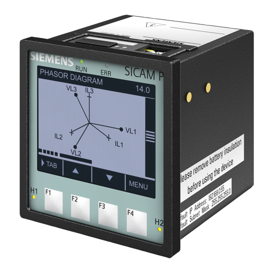
Commissioning and First Steps 9.10 Operation via Display Display Content 9.10.3 Display of the Menus In the main menu, all submenus are listed on the display: [dw_display_main-menu, 1, en_US] Figure 9-18 Display Content Title Password icon Display number Scroll bar Start/end of the list Selected display Current functions of the softkeys... - Page 215 Commissioning and First Steps 9.10 Operation via Display Display of Bar Charts [dw_display-bar-chart, 1, en_US] Figure 9-20 Display of Bar Charts Display of Phasor Diagrams [dw_display_phasor-diagram, 1, en_US] Figure 9-21 Display of Phasor Diagrams SICAM, SICAM P850/P855 7KG85X, Manual E50417-H1040-C482-A9, Edition 03.2022...
-
Page 216: Operation Via Pc
Commissioning and First Steps 9.11 Operation via PC 9.11 Operation via PC General Usage Notes 9.11.1 The device can be operated with HTML pages via the connected PC. Additionally, limited operation of the device is possible with softkeys on the display side in connection with the display. The graphical user interface is stored in the device. -
Page 217: Enabling Javascript (Only For Microsoft Internet Explorer)
ENTER. • Add the self-signed certificates to the certificate trust store of the Web browser. For more information, refer to the document at http://www.siemens.com/gridsecurity, Downloads > Downloads Cyber Security General > Application Notes. • Enter the right password. For more information, refer to chapter 2.2.2 Password... -
Page 218: Changing The Buffer Mechanism (Only For Microsoft Internet Explorer)
Commissioning and First Steps 9.11 Operation via PC [sc_Internet_options_security, 2, en_US] Figure 9-22 Enabling JavaScript • In the window of the Security tab, select the Internet icon. • On the Security tab set Medium-high. • Click Apply. • Click OK. 9.11.2.3 Changing the Buffer Mechanism (only for Microsoft Internet Explorer) NOTE... -
Page 219: Changing The Compatibility Setting (Only For Microsoft Internet Explorer)
Commissioning and First Steps 9.11 Operation via PC • In the Internet options dialog, open the General tab. • In the dialog of the General tab, select the Settings icon. [sc_website_settings_temporary_internet_files, 2, en_US] Figure 9-23 Changing the Buffer Mechanism • In the Website Data Settings tab, click the Every time I visit the webpage icon. -
Page 220: Changing The Security Setting (Only For Microsoft Internet Explorer)
Commissioning and First Steps 9.11 Operation via PC [sc_changing_the_compatibility_setting, 1, en_US] Figure 9-24 Changing the Compatibility Setting • In the Compatibility View Settings dialog, click the Display all websites in Compatibility View. • Enter the IP Address of SICAM P850/P855 device in the Add this website box, click Add. •... - Page 221 Commissioning and First Steps 9.11 Operation via PC • Enable 2 options, the Access data sources across domains and the Initialize and script ActiveX controls not marked as safe for scripting. [sc_security_settings, 2, en_US] Figure 9-25 Changing Security Settings – Miscellaneous SICAM, SICAM P850/P855 7KG85X, Manual E50417-H1040-C482-A9, Edition 03.2022...
-
Page 222: Number Of Connections Via Html
Commissioning and First Steps 9.11 Operation via PC [sc_Security_settings_trusted_site_zone, 3, en_US] Figure 9-26 Changing Security Settings – ActiveX Controls and Plug-Ins • Click OK. NOTE If the Windows system is reinstalled, you must reconfigure the settings related to the Microsoft Internet Explorer. -
Page 223: Layout Of The Web Page
Commissioning and First Steps 9.11 Operation via PC 9.11.2.7 Layout of the Web Page [le_layout_user_interface_p85x, 1, en_US] Figure 9-27 Layout of the Web Page Logout Online help Active tab (light blue) Inactive tab (dark blue) Navigation bar Button Status bar Dialog window Navigation window 9.11.2.8... - Page 224 Commissioning and First Steps 9.11 Operation via PC The navigation window of the Information tab contains: • Show device information • Operational log Show Device Information • Click Show device information in the navigation window. [sc_device_information, 1, en_US] Figure 9-28 Information Tab, Show Device Information SICAM, SICAM P850/P855 7KG85X, Manual E50417-H1040-C482-A9, Edition 03.2022...
-
Page 225: Get Default Configuration
Commissioning and First Steps 9.11 Operation via PC Message Logs Menu – Operational Log The Message Logs menu contains operational indications registered and saved by the device during opera- tion. The device can save up to 128 operational indications. When the storage capacity is exceeded, the oldest indications will be overwritten successively. -
Page 226: Open Configuration From File
Commissioning and First Steps 9.11 Operation via PC [sc_Get_device_configuration, 2, en_US] Figure 9-30 Configuration Tab, Get Default Configuration The factory settings (= passive set of parameters) are restored, and the status of the "parameter set for config- uration" changes from "equal to active" to "modified". 9.11.2.10 Open Configuration from File If you have selected Open configuration from file in the Configuration tab, you can open an existing file in a... -
Page 227: Activation And Cancel Of The Configuration Change
Commissioning and First Steps 9.11 Operation via PC NOTE If you have activated the option in your Web browser to transfer the local directory name together with the file name when uploading files, the total number of characters in the directory and file names must not exceed 100 English characters. -
Page 228: Commissioning
• Check the polarity and the phase assignment at the instrument transformers. Siemens recommends leaving the device for a minimum of 2 hours in the operating room, before using it to allow temperature equalization and to avoid dimness and condensation. -
Page 229: Starting The Device With The Default Ip Address
Commissioning and First Steps 9.12 Commissioning • Switch the alternating voltages and alternating currents to be measured at the measurement object on the measuring lines. • Enter the IP address (default: 192.168.0.55) in the Web browser. • Enter the Password for the Web Login. •... -
Page 230: New Device At Initial Commissioning
Firmware Update at Initial Commissioning NOTE Check the Siemens Internet site whether a new firmware version is available and update your firmware if necessary. You can find the manuals and the firmware via the download area in the Siemens Internet under: http://www.siemens.com/sicam-p850... - Page 231 Commissioning and First Steps 9.12 Commissioning [sc_Save config to file, 2, en_US] Figure 9-33 Configuration Tab, Save Configuration to File • Click either Save active configuration or Save passive configuration. The File Download dialog opens. You can save the downloaded configuration. For more information, refer to File download >...
- Page 232 Commissioning and First Steps 9.12 Commissioning • Click Choose file. • Select the desired file (extension .cfg) in the directory. • Click Open. The selected path is inserted in the Browse field. • Click Open. The device configuration from the CFG file is loaded. NOTE If you have activated the option in your Web browser to transfer the local directory name together with the file name when uploading files, the total number of characters in the directory and file names must not...
- Page 233 SICAM, SICAM P850/P855 7KG85X, Manual E50417-H1040-C482-A9, Edition 03.2022...
-
Page 234: Troubleshooting, Repair, And Fallback Mode
Troubleshooting, Repair, and Fallback Mode 10.1 Failures and LED Displays 10.2 Fallback Mode 10.3 Customer Support Functions SICAM, SICAM P850/P855 7KG85X, Manual E50417-H1040-C482-A9, Edition 03.2022... -
Page 235: 10.1 Failures And Led Displays
SICAM P850/P855 which can only be replaced by the manufacturer according to the guidelines for Electro- static sensitive devices (ESD). If you suspect any damage on the device, Siemens recommends sending the entire device to the manufac- turer. For this purpose, it is best to use the original transport packaging or similar packaging. -
Page 236: Led Indications
Troubleshooting, Repair, and Fallback Mode 10.1 Failures and LED Displays LED Indications 10.1.3 Table 10-1 Meaning of LEDs Description LED is off. LED is on. LED is flashing (0.2 s on, 0.2 s off). LEDs according to configuration If an indication is assigned to an LED (see chapter 13.3.1.2 LEDs): •... - Page 237 Troubleshooting, Repair, and Fallback Mode 10.1 Failures and LED Displays LED Combination Description HTTPS Certificate Generation HTTPS certificate is being generated after the IP address is changed. SICAM, SICAM P850/P855 7KG85X, Manual E50417-H1040-C482-A9, Edition 03.2022...
-
Page 238: Fallback Mode
Troubleshooting, Repair, and Fallback Mode 10.2 Fallback Mode 10.2 Fallback Mode Function Description 10.2.1 The firmware of the device contains a complete application for the operation of the device and runs in 2 modi- fications, depending on the operating state: •... - Page 239 Troubleshooting, Repair, and Fallback Mode 10.2 Fallback Mode [sc_fallback_mode, 1, en_US] Figure 10-1 Fallback Mode, Information Tab (Detail) Maintenance In the Maintenance tab, you can start the application or set the device in the default factory settings state. SICAM, SICAM P850/P855 7KG85X, Manual E50417-H1040-C482-A9, Edition 03.2022...
- Page 240 Troubleshooting, Repair, and Fallback Mode 10.2 Fallback Mode [sc_fallback_mode_run_app, 1, en_US] Figure 10-2 Fallback Mode, Maintenance Tab Firmware Upload with Secure Factory Reset If you select a valid firmware package and click Upload, the entire internal non-volatile memory is cleared. As a result, all the user settings and sensitive data including audit logs are deleted.
- Page 241 Troubleshooting, Repair, and Fallback Mode 10.2 Fallback Mode [sc_q100_ FB_upload_status information, 1, en_US] Figure 10-3 Fallback Mode, Status Information NOTE The whole operation takes more than 3 min, and must not be interrupted, for example by a power loss; otherwise, the device cannot recover and must be sent back to the factory. The Maintenance tab also displays the following sections: •...
-
Page 242: Customer Support Functions
NOTE For the analysis of a potential problem or malfunction, contact the Siemens Customer Support Center. The following table contains URL addresses that can be used if the Siemens Customer Support Center needs to execute a diagnostic analysis. HTML Page (URL) - Page 243 Click Send. • Read the data via the internal diagnosis server or use the device test functions via Modbus and inform the Siemens Customer Support Center. • Select no for the Activate diagnosis function 1 and 2. SICAM, SICAM P850/P855 7KG85X, Manual...
-
Page 244: Maintenance, Storage, Transport
Maintenance, Storage, Transport 11.1 Maintenance, Storage, and Transport SICAM, SICAM P850/P855 7KG85X, Manual E50417-H1040-C482-A9, Edition 03.2022... -
Page 245: Maintenance, Storage, And Transport
+10 °C to +35 °C (+50 °F to +95 °F). Siemens furthermore recommends connecting the device to supply voltage once a year for 1 to 2 days in order to form the inserted electrolytic capacitors. This procedure should also be carried out before operating the device. -
Page 246: Technical Data
Technical Data 12.1 Technical Data 12.2 Test Data 12.3 Dimensions SICAM, SICAM P850/P855 7KG85X, Manual E50417-H1040-C482-A9, Edition 03.2022... -
Page 247: Technical Data
Technical Data 12.1 Technical Data 12.1 Technical Data Power Supply 12.1.1 Direct Voltage Rated input voltages 24 V to 250 V Admissible input voltage tolerance ±20 % Permitted ripple of the input voltage 15 % Maximum inrush current At ≤ 110 V <... -
Page 248: Communication Interfaces
Technical Data 12.1 Technical Data Inputs for Alternating Current Measurements, Connector Block E - Cat III Input alternating currents Rated input current range AC 1 A to 5 A (autorange) Max. input current AC 10 A Power consumption per input At 1 A 4 mVA At 5 A... -
Page 249: Environmental Conditions And Climatic Stress Tests
Technical Data 12.1 Technical Data Serial Interface RS485 Connection Terminal side, 9-pin D-sub socket Protocol Refer to 13.2.5.1 Communication Serial Baud rate (adjustable) Modbus RTU (optional): Min. 1200 bit/s Max. 115 200 bit/s IEC 60870-5-103 (optional): Min. 9600 bit/s Max. 38 400 bit/s Maximum distance of transmission Max. -
Page 250: General Data
Technical Data 12.1 Technical Data Air humidity data Mean relative humidity per year ≤ 75 % Maximum relative humidity 95 % 30 days a year Condensation during operation Not permitted Condensation during transport and Permitted storage Altitude and operation site Max. -
Page 251: Test Data
Technical Data 12.2 Test Data 12.2 Test Data Reference Conditions according to IEC 62586-1 for Determining Test Data 12.2.1 Ambient temperature 23 °C ± 2 °C Relative humidity 40 % to 60 % RH Supply voltage ± 1 % Phases (3-wire network) External continuous magnetic fields DC field: ≤... -
Page 252: Mechanical Stress Tests
Technical Data 12.2 Test Data High frequency electromagnetic field, ampli- 10 V/m tude‑modulated 80 MHz to 3 GHz Class III, IEC 61000-4-3 80 % AM 1 kHz Fast transient bursts 2 kV; 5 ns/50 ns; 5 kHz Class III, IEC 61000-4-4 Burst length: 15 ms Repetition rate: 300 ms Both polarities... -
Page 253: Safety Standards
Technical Data 12.2 Test Data Shock Half-sine resistance IEC 60068-2-27 test Ea 5 g acceleration, duration 11 ms, every 3 shocks in both directions of the 3 axes Seismic Vibration Sinusoidal IEC 60068-3-3 test Fc 1 Hz to 8 Hz: ±7.5 mm amplitude (horizontal axis) 1 Hz to 8 Hz: ±3.5 mm amplitude (vertical axis) 8 Hz to 35 Hz: 2 g acceleration (horizontal axis) 8 Hz to 35 Hz: 1 g acceleration (vertical axis) -
Page 254: Dimensions
Technical Data 12.3 Dimensions 12.3 Dimensions Mass Device without display: approx. 0.49 kg Device with display, without cover: approx. 0.52 kg Device with display, with cover: approx. 0.6 kg Dimensions (W x H x D) 96 mm x 96 mm x 103 mm 3.78 inch x 3.78 inch x 4.06 inch SICAM, SICAM P850/P855 7KG85X, Manual E50417-H1040-C482-A9, Edition 03.2022... - Page 255 Technical Data 12.3 Dimensions [dw_dimensions_DIN_rail, 1, en_US] Figure 12-1 Dimensional Drawing of SICAM P850/P855, DIN Rail Device SICAM, SICAM P850/P855 7KG85X, Manual E50417-H1040-C482-A9, Edition 03.2022...
- Page 256 Technical Data 12.3 Dimensions [dw_dimensions_display, 1, en_US] Figure 12-2 Dimensional Drawing of SICAM P850/P855 with Display SICAM, SICAM P850/P855 7KG85X, Manual E50417-H1040-C482-A9, Edition 03.2022...
- Page 257 Technical Data 12.3 Dimensions [dw_dimensions_display_and_cover, 1, en_US] Figure 12-3 Dimensional Drawing of SICAM P850/P855 with Display and Cover SICAM, SICAM P850/P855 7KG85X, Manual E50417-H1040-C482-A9, Edition 03.2022...
- Page 258 Technical Data 12.3 Dimensions [dw_cut_out_p85x, 1, en_US] Figure 12-4 Cut-Out in Switch Panel SICAM, SICAM P850/P855 7KG85X, Manual E50417-H1040-C482-A9, Edition 03.2022...
- Page 259 SICAM, SICAM P850/P855 7KG85X, Manual E50417-H1040-C482-A9, Edition 03.2022...
-
Page 260: Operational Indications And Operating Parameters
Operational Indications and Operating Parameters 13.1 Operational Indications 13.2 Basic Functions 13.3 Advanced Functions SICAM, SICAM P850/P855 7KG85X, Manual E50417-H1040-C482-A9, Edition 03.2022... -
Page 261: Operational Indications
Operational Indications and Operating Parameters 13.1 Operational Indications 13.1 Operational Indications Operational Indications 13.1.1 Indication Description Notes Device OK The device startup was successful. Indication ON: Device ready Battery Failure Battery voltage < 2.7 V or no Indication ON: Battery failure battery inserted Time Synchronization Error during the time synchroniza-... - Page 262 Operational Indications and Operating Parameters 13.1 Operational Indications Indication Description Notes Modbus Serial OK The Modbus serial communication Indication ON: At least 1 serial message was received has received a valid Modbus during the set communication supervision time. The time (Modbus RTU (Slave)) message.
- Page 263 Operational Indications and Operating Parameters 13.1 Operational Indications Indication Description Notes SD Card Error Indication of an SD card error SD card defective or read/write error Load Profile Period Indication that a period has been Only Indication on is logged. Closed closed.
-
Page 264: Basic Functions
Operational Indications and Operating Parameters 13.2 Basic Functions 13.2 Basic Functions Device and Language 13.2.1 Table 13-1 Settings for Device and Language Parameter Default Setting Setting Range Device name DEVICE Max. 31 ASCII characters Language English (US) ENGLISH (US) User language according to User language preselec- tion: DEUTSCH (DE) or CHINESE (CN) -
Page 265: Date And Time
Operational Indications and Operating Parameters 13.2 Basic Functions Table 13-5 Settings for Logon Configurations Parameter Default Setting Setting Range Logon activation To disable the logon function, select no To enable the logon function, select yes Logon password 000000 Any, 6 to 14 characters Session timeout (min) 10 min 0 min (no timeout) to 1440 min (1 day) -
Page 266: Ac Measurement
Operational Indications and Operating Parameters 13.2 Basic Functions Parameter Default Setting Setting Range Additional Parameters if Source is Fieldbus Error indication after 10 min 2 min to 120 min AC Measurement 13.2.3 Table 13-7 Settings for AC Measurement Parameter Default Setting Setting Range AC measurement Rated frequency... -
Page 267: Ethernet Communication
Operational Indications and Operating Parameters 13.2 Basic Functions Ethernet Communication 13.2.4 13.2.4.1 Communication Ethernet Table 13-8 Settings for Communication Ethernet Parameter Default Setting Setting Range Communication Ethernet 192.168.0.55 IP address 0.0.0.0 = DHCP 255.255.255.0 Subnet mask 192.168.0.1 Default gateway Ethernet switch on Enable SNMP Bus protocol Modbus TCP... -
Page 268: Protocol Iec 61850
Operational Indications and Operating Parameters 13.2 Basic Functions 13.2.4.3 Protocol IEC 61850 Table 13-10 Settings for IEC 61850 Parameter Default Setting Setting Range IED Name SICAM_P850/P855_01 Any, max. 60 characters Only a-z, A-Z, _, 0-9 are permitted. The first character must be an alpha character. Voltage - Dead band 1 % to 5 %, in 1 % steps Current - Dead band... - Page 269 Operational Indications and Operating Parameters 13.2 Basic Functions Parameter Default Setting Setting Range Baud rate 9600 bit/s 9600 bit/s 19 200 bit/s 38 400 bit/s Measured value range 120 % 120 % equivalent to a measured value 240 % range from -4096 to +4095 (-120 equivalent to a measured value % to +120 %) range from -4096 to +4095 (-120...
-
Page 270: Advanced Functions
Operational Indications and Operating Parameters 13.3 Advanced Functions 13.3 Advanced Functions Process Connections 13.3.1 13.3.1.1 Binary Outputs Table 13-12 Settings for Binary Outputs Parameter Default Setting Setting Range Source type Indication Indication Energy counter Source Type Indication -none- Acc. to list box Indication Source inverted (can be set individually for all... -
Page 271: Automation Functions
Operational Indications and Operating Parameters 13.3 Advanced Functions Parameter Default Setting Setting Range -none- Acc. to list box Limit violation and Group Indication Only the indications for the Designation can be changed during the parame- parameterization of the binary terization. outputs are displayed which can be used according to the current device settings. -
Page 272: Display
Operational Indications and Operating Parameters 13.3 Advanced Functions Display 13.3.3 13.3.3.1 Display Settings Table 13-16 Settings for Display Parameter Default Setting Setting Range Contrast 0 to 10 Time until dimmed 1 min to 99 min Refresh time 1000 330 ms to 3000 ms Inverse display Phase label (L1, L2, L3) -
Page 273: Energy Management
Operational Indications and Operating Parameters 13.3 Advanced Functions Parameter Default Setting Setting Range 2 measured values, numerical: -not assigned- The selection of measured values depends on the network type. • Display 1, numerical Designation can be changed during • Display 2, numerical the parameterization. -
Page 274: Energy Freeze
Operational Indications and Operating Parameters 13.3 Advanced Functions 13.3.4.2 Energy Freeze Table 13-19 Settings for Energy Freeze Parameter Default Setting Setting Range Interval 10 min 10 min, 15 min, 30 min, 60 min Power Quality Functions 13.3.5 13.3.5.1 Event Records Table 13-20 Settings for Event Records Parameter... -
Page 275: Records Parameters (Only Sicam P855)
Operational Indications and Operating Parameters 13.3 Advanced Functions Parameter Default Setting Setting Range Tolerance unit Percentage Percentage Numerical Upper threshold 110.00 % of nominal current 5.0 % to 200.0 % of the nominal current Lower threshold 90.00 % of nominal current 0.00 % to 99.99 % of the nominal current Hysteresis... -
Page 276: 50160 Report (Only Sicam P855)
Operational Indications and Operating Parameters 13.3 Advanced Functions 13.3.5.5 EN 50160 Report (only SICAM P855) Table 13-24 Settings for EN 50160 Report Parameter Default Setting Setting Options General Information Company: – Any text displayed in the printout of the power-quality Department: report Supervisor:... - Page 277 SICAM, SICAM P850/P855 7KG85X, Manual E50417-H1040-C482-A9, Edition 03.2022...
-
Page 278: Glossary
Glossary Alternating Current Client Device in the communication network that sends data requests or commands to the server devices and receives responses from them COMTRADE COMmon format for TRAnsient Data Exchange CRC error Cyclic Redundancy Check: The cyclic redundancy check is a method of determining a test value for data (for example, for data transmission in computer networks) with the purpose to detect errors during the transmis- sion or duplication of data. - Page 279 Glossary Intelligent Electronic Device Instantiated IED Description file: It defines the configuration of one IED for a project and is used as data exchange format from the IED configurator to the system configurator. Indication off Status of the indication changes from ON to OFF, that is the indication is deleted Indication on Status of the indication changes from OFF to ON, that is the indication is currently present Internet Protocol...
- Page 280 Glossary Power System TT The Power transformer is neutral-point grounding and the housing of the electric equipment connects to the neutral point. Power Quality RJ45 Connector type RS485 Interface standard for digital, wire-based, differential, serial data transmission Real-Time Clock See Modbus RTU Server Sends data upon request by the client SNMP...
- Page 281 SICAM, SICAM P850/P855 7KG85X, Manual E50417-H1040-C482-A9, Edition 03.2022...
Need help?
Do you have a question about the SICAM 7KG85X and is the answer not in the manual?
Questions and answers