Advertisement
Table of Contents
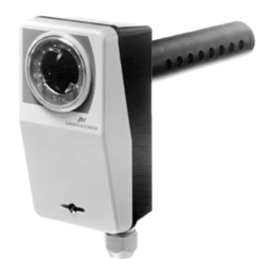
QFM81 Series
Duct Hygrostats
Description
Features
Application
Product Numbers
Mode of Operation
QFM81.21
On /off hygrostat with microswitch, and temperature-compensated humidity sensor for
temperature-independent humidity measurements.
• Stabilized sensing strip (good linearity, very stable even at high humidity, insensitive
to dust and contaminated air).
• Can be mounted in ventilating ducts or rooms.
For controlling humidification equipment and dehumidification equipment.
Product
Setpoint Range
Number
QFM81.2
15 to 95% r.h.
QFM81.21
NOTE:
Includes a mounting flange (for duct or wall mounting) and a sealing ring (for
duct mounting).
The hygrostat acquires the relative humidity of the air with its humidity sensor, which is
a stabilized, plastic strip. The strip actuates a microswitch with a fixed switching
differential X
and a potential-free contact output (SPDT), depending on the relative
d
humidity of the air. If the actual humidity deviates from the adjusted setpoint, the
hygrostat switches the associated humidification or dehumidification equipment on or
off as shown in the following function diagram (Figure 1).
Technical Instructions
Switching
Differential
(W
)
h
(X
)
d
Approx. 4% rh
Document No. 155-707
April 21, 2010
QFM81.2
Degree of
Protection
Adjustment
IP 30
IP 55
Siemens Industry, Inc.
Setpoint
Externally
Internally
Advertisement
Table of Contents

Related Manuals for Siemens QFM81 Series


Summary of Contents for Siemens QFM81 Series
- Page 1 Technical Instructions Document No. 155-707 April 21, 2010 QFM81 Series Duct Hygrostats QFM81.21 QFM81.2 Description On /off hygrostat with microswitch, and temperature-compensated humidity sensor for temperature-independent humidity measurements. • Stabilized sensing strip (good linearity, very stable even at high humidity, insensitive Features to dust and contaminated air).
-
Page 2: Mechanical Design
Technical Instructions QFM81 Series Duct Hygrostats Document Number 155-707 April 21, 2010 r. h. [%] Relative humidity in % Microswitch 1−2 Humidification 1−3 Dehumidification Setpoint Actual value Switching differential Time Figure 1. Function Diagram. If the relative humidity exceeds the adjusted setpoint, the potential-free contact of the microswitch will change over from 1−2 to 1−3. -
Page 3: Mounting Notes
QFM81 Series Duct Hygrostats Technical Instructions Document Number 155-707 April 21, 2010 Mounting Notes If the duct hygrostat is used for control, it must be mounted in the exhaust air duct after the room to be controlled. Air Duct Mounting If the duct hygrostat is used for monitoring the maximum or minimum humidity level, it imust be mounted in the supply air duct. -
Page 4: Specifications
Technical Instructions QFM81 Series Duct Hygrostats Document Number 155-707 April 21, 2010 Specifications Setpoint range 15 to 95% rh Control mode On /off Switching differential Approximately 4% rh (fixed) Type of switch Potential-free microswitch (SPDT) Contact rating Maximum 5 (3) A, 24 Vac/Vdc... - Page 5 QFM81 Series Duct Hygrostats Technical Instructions Document Number 155-707 April 21, 2010 Dimensions 5.51 2.87 (140) (73) 1.64 (41,7) Pg 11 0.22 (5,5) ø 1.18 2.13 (ø 30) (54) A - B 2.67 (68) 1.65 (42) 0.24 1.10 (28) Figure 4. Dimensions in Inches (Millimeters).
Need help?
Do you have a question about the QFM81 Series and is the answer not in the manual?
Questions and answers