
Related Manuals for Siemens SICAM


Summary of Contents for Siemens SICAM
- Page 1 Preface Open Source Software Table of Contents SICAM Delivery Fault Passage Indicator Introduction Product Specification V01.20 Device Functions Manual Troubleshooting Index E50417-H1040-C580-A7...
- Page 2 Document version: E50417-H1040-C580-A7.00 Trademarks Edition: 11.2019 SIPROTEC, DIGSI, SIGRA, SIGUARD, SIMEAS SAFIR, SICAM, Version of the product described: V01.20 and MindSphere are trademarks of Siemens. Any unauthor- ized use is prohibited.
-
Page 3: Preface
Preface Purpose of the Manual This manual describes the functions and operation of SICAM FPI device. In particular, you will find: • Compilation of the Technical Data 3.1.1 Technical Data • Information regarding the configuration of the device and a description of the device functions 4.1.1 Device Functions... - Page 4 Qualified electrical engineering personnel in the sense of this document are people who can demonstrate technical qualifications as electrical technicians. These persons may commission, isolate, ground and label devices, systems and circuits according to the standards of safety engineering. SICAM, Fault Passage Indicator, Manual E50417-H1040-C580-A7, Edition 11.2019...
- Page 5 Caution, risk of electric shock Caution, risk of danger, ISO 7000, 0434 Protective Insulation, IEC 60417, 5172, Safety Class II devices Guideline 2002/96/EC for electrical and electronic devices Guideline for the Eurasian Market SICAM, Fault Passage Indicator, Manual E50417-H1040-C580-A7, Edition 11.2019...
- Page 6 SICAM, Fault Passage Indicator, Manual E50417-H1040-C580-A7, Edition 11.2019...
-
Page 7: Open Source Software
License Conditions provide for it you can order the source code of the Open Source Software from your Siemens sales contact – against payment of the shipping and handling charges – for a period of at least 3 years after purchase of the product. We are liable for the product including the Open Source Software contained in it pursuant to the license conditions applicable to the product. - Page 8 SICAM, Fault Passage Indicator, Manual E50417-H1040-C580-A7, Edition 11.2019...
-
Page 9: Table Of Contents
2.1.11 Installation of Phase Sensors ..................23 2.1.12 Installation of Ground Sensor..................25 2.1.13 Mounting of Ground Sensor on Shielded Cable............27 2.1.14 Replacing the SICAM FPI Battery...................28 2.1.15 Environmental Protection Hints..................29 2.1.16 Terminal Diagram......................30 2.1.17 Dimensional Drawings....................31 Product Specification..........................33 Technical Data........................ - Page 10 Table of Contents 4.1.7 Battery Health Condition....................47 4.1.8 Blinking Lamp Output....................47 4.1.9 Binary Outputs......................47 Troubleshooting............................49 Troubleshooting....................... 50 Index................................51 SICAM, Fault Passage Indicator, Manual E50417-H1040-C580-A7, Edition 11.2019...
-
Page 11: Delivery
Delivery Delivery SICAM, Fault Passage Indicator, Manual E50417-H1040-C580-A7, Edition 11.2019... -
Page 12: Delivery
ICAO-TI/IATA-DGR: UN 3091 lithium metal batteries contained in equipment, 9, preconditions of Section II PI 970 met The lithium metal cell for SICAM FPI (as a spare part) is also subject to the special provision SP188 mentioned above, but classified according to: •... -
Page 13: Introduction
Introduction Overview SICAM, Fault Passage Indicator, Manual E50417-H1040-C580-A7, Edition 11.2019... -
Page 14: Overview
SICAM FPI. In this condition, the corre- sponding LEDs blink. SICAM FPI is used as a fault detection and indication unit. SICAM FPI is used in the feeder and distribution automation of secondary medium-voltage systems that ranges from typically 10 kV to 36 kV. -
Page 15: Hardware Components
• Push Button - Push button is used for resetting the device manually (RST) and for executing the function check (FN.CHK) and battery check (BATT.CHK). SICAM, Fault Passage Indicator, Manual E50417-H1040-C580-A7, Edition 11.2019... -
Page 16: Features
Binary outputs X3 and X4 Phase faults L1, L2, L3 optical input Remote reset input X1 (dry contact) Features 2.1.3 The salient features of SICAM FPI are: • Self-sustained - Using long-life lithium battery • Safe - Complies with the IEC 61010-1 safety standards •... -
Page 17: Applications
The device is used in 50-Hz/60-Hz networks. • The device is primarily intended for radial or open ring medium-voltage cable networks. 2.1.5 MLFB (Ordering Code) Table 2-1 SICAM FPI Selection and Ordering Data Description Versions Order no. 10 11 12 13 14 15 16 SICAM FPI, non-directional 6 M D 2 3 1 0 - 0 □... -
Page 18: Sicam Fpi Variants
With 1 ground-fault sensor (for E), Plastic fibre-optic cable (3 m in length) SICAM FPI Variants 2.1.6 The following tables show the list of SICAM FPI variants that can be ordered based on the standard MLFB. Table 2-2 SICAM FPI Variants (Type 1 Series) MLFB... - Page 19 Introduction 2.1 Overview Table 2-3 SICAM FPI Variants (Type 2 Series) MLFB Phase Input Ground Input BO Sensor Type (Quantity) 6MD2310-0AE00-0AA0 3 phase + 1 ground 6MD2310-0BF00-0AA0 3 phase 6MD2310-0CG00-0AA0 1 ground 6MD2310-0DE00-0AA0 3 phase + 1 ground 6MD2310-0EG00-0AA0 1 ground Based on the device MLFB, the front view and rear view of the device varies.
-
Page 20: Device Installation
2.1.7 Device Installation The SICAM FPI device is intended for indoor installation in an RMU panel. Execute the following procedure to install and mount the device in RMU: Create a slot of dimensions measuring 92+0.8 mm x 45+0.8 mm (W x H) to house the device in RMU ²... -
Page 21: Commissioning
Confirm that the correct DIP switch settings have been configured to meet the application requirements. Post-Installation and Commissioning 2.1.9 Procede as follows after installation and commissioning of the device. To use SICAM FPI for the first time, pull out the battery isolation tab to activate the device as shown in ² Figure 2-10. - Page 22 [dw_fpidipswtool-global, 1, en_US] Figure 2-11 Changing DIP Switch Settings At the rear side of SICAM FPI, remove the stickers placed on the locknut of the optical inputs (L1, L2, L3, ² and E). If SICAM FPI is not responding even after pulling out the battery isolation tab, this may be due to passiva- ²...
-
Page 23: Preparing The Sensors For Installation
Before installing the sensors on the underground cables, disconnect the power to the respective cables. Installation of Phase Sensors 2.1.11 To install the phase sensor, follow the procedure: Loosen the M4 fixing bolts on both sides using a 7-mm wrench. ² SICAM, Fault Passage Indicator, Manual E50417-H1040-C580-A7, Edition 11.2019... - Page 24 Flux concentrator bracket Core cable M4 fixing bolts Rotary switch for selecting fault-current threshold limit Gland Locknut Plastic fibre-optic cable Repeat the procedures mentioned before for installing the other phase sensors. ² SICAM, Fault Passage Indicator, Manual E50417-H1040-C580-A7, Edition 11.2019...
-
Page 25: Installation Of Ground Sensor
The plastic fibre-optic cable should be inserted into the gland till it contacts the internal component at both the ends of sensor and the device. The locknut should be fixed tightly. NOTE Siemens recommends using the following color sequence for the strip color fibre-optic cables supplied along with the SICAM FPI. •... - Page 26 Rotary switch for selecting fault-current threshold limit Gland Locknut Plastic fibre-optic cable The following figure shows how SICAM FPI is connected with phase sensors and ground sensor via the plastic fibre-optic cable. SICAM, Fault Passage Indicator, Manual E50417-H1040-C580-A7, Edition 11.2019...
-
Page 27: Mounting Of Ground Sensor On Shielded Cable
Introduction 2.1 Overview [dw_fpiphaearsens-280314, 2, --_--] Figure 2-15 SICAM FPI Connected with Phase and Ground Sensors Phase conductor in a 3-core cable construction Phase conductor Phase sensor Plastic fibre-optic cable Locknut Gland Ground sensor Mounting of Ground Sensor on Shielded Cable 2.1.13... -
Page 28: Replacing The Sicam Fpi Battery
Always ensure that the exposed shield area is sealed to avoid any damage and stress. Replacing the SICAM FPI Battery 2.1.14 You can replace the SICAM FPI battery when it is damaged or exhausted. To replace the battery, procede as follows: Remove the SICAM FPI front cover with the help of a screwdriver. -
Page 29: Environmental Protection Hints
When disposing of or transferring a mobile storage device, Siemens strongly recommends physically destroying it or completely deleting data from the mobile storage device by using a commercially available computer data erasing software. -
Page 30: Terminal Diagram
Terminal Diagram 2.1.16 The terminal diagram shows the terminal number and terminal blocks of the 6MD2310-0AX00-0AA0 (X repre- sents the type of sensors) variant of SICAM FPI. [dw_fpirearv-210114-01, 2, --_--] Figure 2-18 Terminal Diagram Table 2-4 Terminals Specification and Recommended Lugs... -
Page 31: Dimensional Drawings
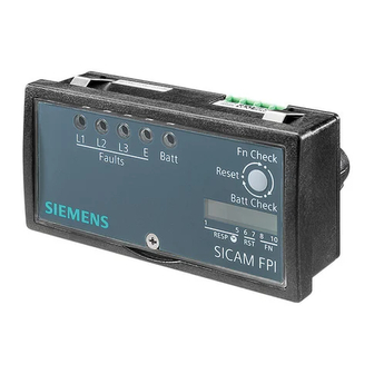
Introduction 2.1 Overview Dimensional Drawings 2.1.17 This section shows the dimensional drawings and different views of SICAM FPI. [dw_sicam-fpi_frbtv, 1, en_US] Figure 2-19 Front View [dw_fpirearv-210114-01, 2, --_--] Figure 2-20 Rear View SICAM, Fault Passage Indicator, Manual E50417-H1040-C580-A7, Edition 11.2019... - Page 32 SICAM, Fault Passage Indicator, Manual E50417-H1040-C580-A7, Edition 11.2019...
-
Page 33: Product Specification
Product Specification Technical Data Type Testing SICAM, Fault Passage Indicator, Manual E50417-H1040-C580-A7, Edition 11.2019... -
Page 34: Technical Data
Internal battery Lithium battery (Li-SOCl ) type Standard AA cell size/3.6 V/2400 mAh Expected shelf life of the SICAM FPI with battery installed is at least 10 years, including > 2000 hours of flashing time in active mode (fault indication mode) - Page 35 Humidity range 0 to 95 %, non-condensing Altitude above sea level Maximum up to 2000 m General Minimum and maximum operating temperature of -55 °C and +85 °C connected plastic fibre-optic cable SICAM, Fault Passage Indicator, Manual E50417-H1040-C580-A7, Edition 11.2019...
-
Page 36: Type Testing
Cat. III shorted Battery terminals 3.5 kV, 50 Hz Cat. III shorted SICAM FPI is classified into overvoltage category III and pollution degree 2 as per the device safety standard IEC 61010-1. Table 3-3 Environmental Test Type Test Reference Requirement... - Page 37 Requirement IP Tests IP 50 IEC 60529 SICAM FPI indicator front IP 20 SICAM FPI indicator rear IP 67 SICAM FPI sensor - phase and ground Table 3-4 Routine/Production Test Type Test Reference Requirement Production test IEEE 495 Clause number. 4.2.1 and 4.2.2 SICAM, Fault Passage Indicator, Manual E50417-H1040-C580-A7, Edition 11.2019...
- Page 38 SICAM, Fault Passage Indicator, Manual E50417-H1040-C580-A7, Edition 11.2019...
-
Page 39: Device Functions
Device Functions Description SICAM, Fault Passage Indicator, Manual E50417-H1040-C580-A7, Edition 11.2019... -
Page 40: Description
4.1 Description Description Device Functions 4.1.1 This section describes the functions of SICAM FPI. Fault Detection 4.1.2 Phase Detection Single Fault - In the L1, L2, L3 phase, if single fault is detected and the fault current persists for greater than or equal to the set response time, the respective LED blinks to indicate a single fault (1 blink/s) and the phase binary output contact changes its state from open contact to close contact. - Page 41 LED and the binary output remains latched. NOTE To operate the momentary fault reset, connect the NC contact of the incoming circuit breaker/bus supply to the AC 230 V input (X5). SICAM, Fault Passage Indicator, Manual E50417-H1040-C580-A7, Edition 11.2019...
- Page 42 For example, set the DIP 3 to OFF, DIP 4 to ON, and DIP 5 to OFF to get the response time as 80 ms. By default, the factory response-time setting is 40 ms. The following table shows the response time settings of the device. SICAM, Fault Passage Indicator, Manual E50417-H1040-C580-A7, Edition 11.2019...
- Page 43 If the battery voltage is low, the binary output contact X3 switches from open to close 5 times (open time/cycle: 1 s and close time/ cycle: 1 s), thus indicating the low battery status. SICAM, Fault Passage Indicator, Manual E50417-H1040-C580-A7, Edition 11.2019...
- Page 44 To apply the changes in the DIP switch settings, run the complete function test by pressing the push button for less than 3 s. The following diagrams show the DIP switch settings label for the different device variants. SICAM, Fault Passage Indicator, Manual E50417-H1040-C580-A7, Edition 11.2019...
- Page 45 [dw_fpivariant2-280314, 1, --_--] Figure 4-4 6MD2310-0BX00-0AA0 - 3 Phase, 1 Binary Output with 3 Phase Sensors [dw_fpivariant3-280314, 1, --_--] Figure 4-5 6MD2310-0CX00-0AA0 - 1 Ground, 1 Binary Output with 1 Ground Sensor SICAM, Fault Passage Indicator, Manual E50417-H1040-C580-A7, Edition 11.2019...
- Page 46 Auto-reset time (RST TM) 6 - 7 Fault indication on binary output (FUNC SEL) X3, X4 Low battery configuration on binary output (FUNC Disabled SEL) Sensors plastic fibre-optic cable test (FUNC SEL) Disabled SICAM, Fault Passage Indicator, Manual E50417-H1040-C580-A7, Edition 11.2019...
-
Page 47: Fault Indication
When the ground-fault is detected, both the binary outputs change their position from open to close and from close to open and remain in that position until the device is reset. SICAM, Fault Passage Indicator, Manual E50417-H1040-C580-A7, Edition 11.2019... - Page 48 SICAM, Fault Passage Indicator, Manual E50417-H1040-C580-A7, Edition 11.2019...
-
Page 49: Troubleshooting
Troubleshooting Troubleshooting SICAM, Fault Passage Indicator, Manual E50417-H1040-C580-A7, Edition 11.2019... -
Page 50: Troubleshooting
Troubleshooting 5.1 Troubleshooting Troubleshooting This section provides the common problems of SICAM FPI and the recommended solution to resolve the problem. Observations Action • The device is not responding Remove the housing screw and ensure that the paper strip inserted between the battery and battery-clip during shipment is removed. -
Page 51: Index
Commissioning 21 Current sensors 14 Installation Current threshold 14 Ground sensor 0 , 25 Phase sensors 23 Installation of SICAM FPI 20 Default factory settings 46 Device Description 14 Device functions 40 LEDs 15 Dimensions 34 Locknut 0 , 25, 25... - Page 52 Ring main unit 20 Rotary switch 14 Routine/Production Test 36 SCADA 47 Sensors 17 Single fault 40 Spare part 17 Technical data 34 Terminal diagram 30 Troubleshooting 50 Type testing 36 Variants 18 SICAM, Fault Passage Indicator, Manual E50417-H1040-C580-A7, Edition 11.2019...
Need help?
Do you have a question about the SICAM and is the answer not in the manual?
Questions and answers