Siemens SICAM Q100 7KG95 Series Manuals
Manuals and User Guides for Siemens SICAM Q100 7KG95 Series. We have 2 Siemens SICAM Q100 7KG95 Series manuals available for free PDF download: Manual

Siemens SICAM Q100 7KG95 Series Manual (376 pages)
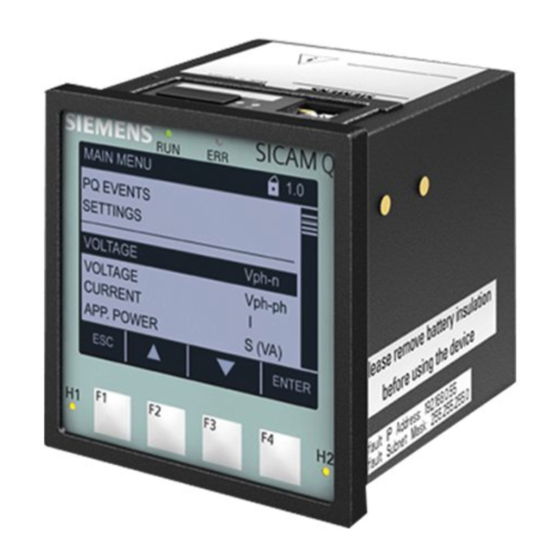
Class A Power Quality Instrument and Power Monitoring Device
Brand: Siemens
|
Category: Measuring Instruments
|
Size: 8 MB
Table of Contents
-
Preface3
-
Introduction15
-
Date/Time32
-
Ethernet47
-
Iec 6185057
-
Measurands92
-
Flicker115
-
General122
-
Binary Inputs123
-
Binary Outputs126
-
SICAM Subdevices130
-
Leds134
-
Limits138
-
Load Profile147
-
Energy Profile157
-
Tariffs159
-
CO2 Emissions167
-
Power Quality169
-
Event Records170
-
Voltage Events172
-
RVC Events181
-
Frequency Events184
-
Waveform Records188
-
Trend Records201
-
Transients206
-
50160 Report210
-
Overview221
-
Syslog237
-
Wind Farm Mode239
-
Clear Data241
-
Message Logs244
-
Audit Log246
-
Event Types246
-
File Download249
-
System Functions265
-
General266
-
Firmware Upload268
-
Safety Notes276
-
Assembly280
-
Access Rights289
-
Commissioning291
-
Operation Via PC302
-
Introduction306
-
Display Content314
-
LED Indications319
-
Fallback Mode321
-
Technical Data329
-
Technical Data330
-
Power Supply330
-
General Data334
-
Test Data335
-
Electrical Tests335
-
Safety Standards337
-
Dimensions338
-
Basic Functions345
-
Date and Time345
-
AC Measurement346
-
Protocol SNMP350
-
Binary Inputs356
-
Binary Outputs356
-
SICAM Subdevices357
-
Leds358
-
Display360
-
Display Settings360
-
Load Profile361
-
Energy Profile362
-
Tariffs362
-
CO2 Emissions363
-
Event Records363
-
Waveform Records364
-
Trend Records366
-
50160 Report367
-
Administration368
-
SICAM Subdevices370
-
Wind Farm Mode372
-
Glossary373
Advertisement

Siemens SICAM Q100 7KG95 Series Manual (448 pages)
Class A Power Quality Instrument and Power Monitoring Device
Brand: Siemens
|
Category: Measuring Instruments
|
Size: 21 MB
Table of Contents
-
Preface
3 -
2 Overview
19 -
-
-
Flicker30
-
Transients31
-
-
6 Security
93 -
-
Assembly114
-
Assembly116
-
Safety Notes117
-
Access Rights120
-
Commissioning122
-
-
-
Hmi180
-
-
Maintenance303
-
Firmware Upload304
-
-
Presets309
-
Message Logs313
-
-
-
Diagnosis319
-
-
AC Calibration326
-
Task Definition327
-
-
Maintenance366
-
Storage366
-
Transport366
-
-
-
Power Supply380
-
General Data386
-
Test Data387
-
Electrical Tests387
-
Safety Standards389
-
Dimensions390
-
-
AC Measurement398
-
Binary Outputs401
-
Leds403
-
Hmi407
-
Display Settings407
-
Load Profile410
-
Tariffs (TOU)410
-
Event Recorders412
-
Administrative419
-
SICAM Subdevices430
-
16.6.11 Syslog440
-
Glossary
441 -
Appendix
445 -
Index
447
Advertisement