Table of Contents
Advertisement
Quick Links
Advertisement
Table of Contents

Related Manuals for Siemens SICAM P 7KG7750


Summary of Contents for Siemens SICAM P 7KG7750
- Page 1 Foreword, Contents Commissioning Operation Power Meter Measured Quantities SICAM P 7KG7750/55 Device Parameterization Parameterization via PC Software Manual Calibration Maintenance, Storage, Transport Technical Data E50417-B1076-C340-A6...
- Page 2 Siemens. Offenders will be liable for damages. All plete conformity or for any errors or omissions.
- Page 3 Validity of the manual This manual is valid for the devices SICAM P 7KG7750/55. Additional support For any questions concerning your system, please contact your local Siemens representative. Hotline Our Customer Support Center provides around-the-clock service. Phone: +49 (1805) 24-8437...
- Page 4 Please ask our Training Center for information on the individual courses available: Siemens AG Siemens Power Academy TD Humboldtstr. 59 90459 Nuremberg Germany Phone: +49 911 433-7415 Fax: +49 911 433-5482 E-mail: poweracademy.ic-sg@siemens.com Internet: http://www.siemens.com/poweracademy Power Meter, SICAM P 7KG7750/55, Manual E50417-B1076-C340-A6, Edition 09.2013...
- Page 5 Comply with all instructions, in order to avoid material damage. Note Important information about the product, product handling or a certain section of the documen- tation, which must be given particular attention. Power Meter, SICAM P 7KG7750/55, Manual E50417-B1076-C340-A6, Edition 09.2013...
- Page 6 (EMC Council Directive 2004/108/EC) and concerning electrical equipment for use within specified voltage limits (Low-voltage Directive 2006/95/EC). This conformity has been established by means of tests conducted by Siemens AG according to the Council Directive in agreement with the generic standards EN 61000- 6-2 and EN 61000-6-4 for the EMC directives, and with the standard EN 61010-1 for the low-voltage directive.
-
Page 7: Table Of Contents
1.4.1 Device Variant SICAM P 7KG7750 ........ - Page 8 Memory Management..........Power Meter SICAM P 7KG7750/55, Manual...
- Page 9 Connection / Transformer ......... Screens Setting on SICAM P 7KG7750 ....... . .
- Page 10 SICAM P 7KG7750........
-
Page 11: Commissioning
Commissioning Contents The following chapters describe all aspects of commissioning. Application and Mode of Operation Delivery Ordering Data Dimensions Block Diagram Interface and Terminals Power Meter SICAM P 7KG7750/55, Manual E50417-B1076-C340-A6, Edition 09.2013... -
Page 12: Application And Mode Of Operation
SICAM P is delivered with pre-programmed default settings. A status line displayed in the measured value screens indicates status, interfacing and diagnos- tic messages for the SICAM P. The display is automatically refreshed every second. Power Meter SICAM P 7KG7750/55, Manual E50417-B1076-C340-A6, Edition 09.2013... -
Page 13: Delivery
This is only valid for the original battery or original spare batteries. For general transport security by shipment as freight: Electric equipment is only to be sent as freight if shut off. Power Meter SICAM P 7KG7750/55, Manual E50417-B1076-C340-A6, Edition 09.2013... -
Page 14: Ordering Data
DC 0 mA to 20 mA 3 relay outputs Front protection class IP 41 IP 65 Communication interface and protocols PROFIBUS DP and Modbus RTU/ASCII / RS485 IEC 60870-5-103 and Modbus RTU/ASCII / RS485 Power Meter SICAM P 7KG7750/55, Manual E50417-B1076-C340-A6, Edition 09.2013... -
Page 15: Sicam P 7Kg7755
Software SICAM P PAR, RS232/RS485 adapter Type RS485 / 5 V-power supply unit / supply voltage AC 230 V/50 Hz RS485 / 5 V-power supply unit / supply voltage AC 120 V/60 Hz Power Meter SICAM P 7KG7750/55, Manual E50417-B1076-C340-A6, Edition 09.2013... -
Page 16: Dimensions
1.4 Dimensions Dimensions 1.4.1 Device Variant SICAM P 7KG7750 Note: All dimensions in mm Fig. 1-1 SICAM P 7KG7750, variant IP 41 Power Meter SICAM P 7KG7750/55, Manual E50417-B1076-C340-A6, Edition 09.2013... - Page 17 1.4 Dimensions Note: All dimensions in mm Fig. 1-2 SICAM P 7KG7750, variant IP 65 Power Meter SICAM P 7KG7750/55, Manual E50417-B1076-C340-A6, Edition 09.2013...
- Page 18 Conductor cross section, rigid max.: 2.5 mm Conductor cross section with ferrule: 1.5 mm Stripping length: 9 mm Tightening torque: 0.4 Nm to 0.5 Nm RS485 interface 9-pole D-Sub miniature female connector Power Meter SICAM P 7KG7750/55, Manual E50417-B1076-C340-A6, Edition 09.2013...
-
Page 19: Device Variant Sicam P 7Kg7755
Conductor cross section, rigid max.: 2.5 mm Conductor cross section with ferrule: 1.5 mm Stripping length: 9 mm Tightening torque: 0.4 Nm to 0.5 Nm RS485 interface 9-pole D-Sub miniature female connector Power Meter SICAM P 7KG7750/55, Manual E50417-B1076-C340-A6, Edition 09.2013... -
Page 20: Block Diagram
1.5 Block Diagram Block Diagram Fig. 1-5 Block diagram SICAM P 7KG7750/55 Note The integrated battery serves to buffer the memory and the real-time clock. Power Meter SICAM P 7KG7750/55, Manual E50417-B1076-C340-A6, Edition 09.2013... - Page 21 Binary inputs (2 contacts with common contact) • Binary outputs (2 contacts with common contact) • Relay outputs (3 contacts with common contact) • Analog inputs (2 channels) • Analog outputs (2 channels) Power Meter SICAM P 7KG7750/55, Manual E50417-B1076-C340-A6, Edition 09.2013...
-
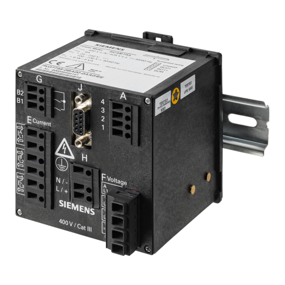
Page 22: Interface And Terminals
Warning about missing protection. Nonobservance of the safety instructions means that death, severe injuries or considerable material damages can occur. • Always connect the earth to the earthing terminal of the SICAM P 7KG7750/55. Power Meter SICAM P 7KG7750/55, Manual E50417-B1076-C340-A6, Edition 09.2013... -
Page 23: Terminal Assignment
Common contact for the internal binary outputs 1 contact contact and 2 Binary output 2 Binary output 1 Protective ground Supply voltage - Supply voltage + A1 to A4 Optional, see Table 1-2, I/O modules Power Meter SICAM P 7KG7750/55, Manual E50417-B1076-C340-A6, Edition 09.2013... - Page 24 (see chapter 1.3) not equipped n.c. 2 binary outputs BO2+ BO1+ BI2+ 2 binary inputs BI1+ AO2- 2 analog outputs AO2+ AO1- AO1+ AI2- 2 analog inputs AI2+ AI1- AI1+ 3 relay outputs Power Meter SICAM P 7KG7750/55, Manual E50417-B1076-C340-A6, Edition 09.2013...
-
Page 25: Assignment Of The Interface
Note All computing devices connected to the RS485 interface port shall be connected to a SELV (Sep- arated Extra Low Voltage) circuit and must comply with the following standard: IEC/EN 60950. Power Meter SICAM P 7KG7750/55, Manual E50417-B1076-C340-A6, Edition 09.2013... -
Page 26: Connection Examples
Note The single ground connection of the instrument transformers is shown for illustration only. Actual grounds must be installed directly at each instrument transformer. 1.6.4.2 Single-phase 10 A Power Meter SICAM P 7KG7750/55, Manual E50417-B1076-C340-A6, Edition 09.2013... -
Page 27: Three-Phase, Three-Wire, Balanced
Nonobservance of the safety instructions means that property damage can result. • The maximum secondary voltage is AC 480 V in this example. Do not exceed the maximum permissible voltage between phase and earth. Power Meter SICAM P 7KG7750/55, Manual E50417-B1076-C340-A6, Edition 09.2013... -
Page 28: Three-Phase, Four-Wire, Balanced
1.6 Interface and Terminals 1.6.4.5 Three-phase, Four-wire, Balanced 10 A 1.6.4.6 Three-phase, Four-wire, Unbalanced (Low-voltage System) resp. 10 A Power Meter SICAM P 7KG7750/55, Manual E50417-B1076-C340-A6, Edition 09.2013... -
Page 29: Three-Phase, Four-Wire, Unbalanced (High-Voltage System)
1.6 Interface and Terminals 1.6.4.7 Three-phase, Four-wire, Unbalanced (High-voltage System) resp. 10 A Power Meter SICAM P 7KG7750/55, Manual E50417-B1076-C340-A6, Edition 09.2013... -
Page 30: Mounting
Steps must be taken to prevent condensation on or within the device during operation. • To prevent accidental contact with energized parts the above described mounting must be taken care-fully and correctly. Power Meter SICAM P 7KG7750/55, Manual E50417-B1076-C340-A6, Edition 09.2013... -
Page 31: Commissioning
Warning about battery change. Nonobservance of the safety instructions means that death, severe injuries or considerable material damages can occur. • All electrical connections must get separated from the device before the battery change. Power Meter SICAM P 7KG7750/55, Manual E50417-B1076-C340-A6, Edition 09.2013... -
Page 32: Electrical Connection
Before initially energizing the device with supply voltage, it shall be situated in the operating area for at least two hours to ensure temperature equalization and to avoid humidity and con- densation problems. Power Meter SICAM P 7KG7750/55, Manual E50417-B1076-C340-A6, Edition 09.2013... -
Page 33: Operation
Operation Contents The following chapters describe the operation of the SICAM P 7KG7750. The operation of the SICAM P 7KG7755 is not described because this device has no display. Screen Display Screen Content Power Meter SICAM P 7KG7750/55, Manual E50417-B1076-C340-A6, Edition 09.2013... -
Page 34: Screen Display
2.2.1 Screen Types The following screen types are available: • three measured values - digital • six measured values - digital • φ U, I, cos • three min-max values Power Meter SICAM P 7KG7750/55, Manual E50417-B1076-C340-A6, Edition 09.2013... -
Page 35: Measured Values - Digital
• measured quantities: U, I, cos φ 10.12 kV 245.4 A 10.34 kV 244.6 A 10.42 kV 249.4 A φ 0.922 ind 0.923 ind 0.927 ind Power Meter SICAM P 7KG7750/55, Manual E50417-B1076-C340-A6, Edition 09.2013... -
Page 36: Min-Max Values
If no date/time is set, the duration of the recording is indicated in hours and minutes. If the time is set, the date and time of recording initiation are indicated. <> Bd/Prm 2/10 29.08 Min-Max 12:30 230.11 233.53 228.59 231.47 227.33 233.48 Power Meter SICAM P 7KG7750/55, Manual E50417-B1076-C340-A6, Edition 09.2013... -
Page 37: Status Bar
Please replace the battery in this case (see chapter 1.6.5). If the password protection is active a lock with a closed fastener will be displayed. Recording of average values active Recording of power values active Power Meter SICAM P 7KG7750/55, Manual E50417-B1076-C340-A6, Edition 09.2013... - Page 38 2.2 Screen Content Power Meter SICAM P 7KG7750/55, Manual E50417-B1076-C340-A6, Edition 09.2013...
-
Page 39: Measured Quantities
Contents The following chapters describe the measured quantities. Measured Quantities - Depend on the Connection Type Formulas and Calculation of Derived Quantities Connection Modes View of Measured Quantities and Error Limits Power Meter SICAM P 7KG7750/55, Manual E50417-B1076-C340-A6, Edition 09.2013... -
Page 40: Measured Quantities - Depend On The Connection Type
COS PHI L3 Active factor cos φ Σ COS PHI Power factor L1 PF L1 Power factor L2 PF L2 Power factor L3 PF L3 Power factor Σ * see Table 3-2, Explanation Power Meter SICAM P 7KG7750/55, Manual E50417-B1076-C340-A6, Edition 09.2013... - Page 41 Active energy L1 total* WpL1t Active energy L2 total* WpL2t Active energy L3 total* WpL3t Active energy Σ total* WpΣt Active energy (3L) demand Wpnet net* * see Table 3-2, Explanation Power Meter SICAM P 7KG7750/55, Manual E50417-B1076-C340-A6, Edition 09.2013...
- Page 42 Apparent energy L2 Apparent energy L3 Apparent energy Σ WΣ Counter 1 / 2 / 3 / 4* Cntr. 1, 2, 3, 4 Binary inputs Analog inputs * see Table 3-2, Explanation Power Meter SICAM P 7KG7750/55, Manual E50417-B1076-C340-A6, Edition 09.2013...
- Page 43 Reactive energy total The sum of the absolute values (without sign) of inductive and capacitive kvarh. Counter 1 / 2 / 3 / 4 Number of limit violations Binary inputs, optional analog inputs Power Meter SICAM P 7KG7750/55, Manual E50417-B1076-C340-A6, Edition 09.2013...
-
Page 44: Formulas And Calculation Of Derived Quantities
No sign! ϕ Power factor cos ϕ Four quadrants according to ϕ note 4 Phase Angle From the fundamental ϕ arctan component only! According to classic measuring devices (electrodynamic power meter) Power Meter SICAM P 7KG7750/55, Manual E50417-B1076-C340-A6, Edition 09.2013... - Page 45 Asymmetrical voltage U or Refer to note 2 Range is 0 to ∞, avoid division current I by 0! THD voltage, current Refer to note 3 − Harmonics From Fourier transformation Power Meter SICAM P 7KG7750/55, Manual E50417-B1076-C340-A6, Edition 09.2013...
-
Page 46: Remarks To The Measuring Quantities
⎞ ϕ π ϕ π − ⎜ ⎟ ⎜ ⎟ ⎝ ⎠ ⎝ ⎠ ⎛ ⎞ ⎛ ⎞ ϕ π ϕ π − ⎜ ⎟ ⎜ ⎟ ⎝ ⎠ ⎝ ⎠ Power Meter SICAM P 7KG7750/55, Manual E50417-B1076-C340-A6, Edition 09.2013... - Page 47 : RMS value of the fundamental component of the measured quantity Inserting the values into the equation results in: Equation 9: − Inserting 1/M1 into the root results in: Equation 10: − − Power Meter SICAM P 7KG7750/55, Manual E50417-B1076-C340-A6, Edition 09.2013...
- Page 48 φ = positive + ind cos φ = negative + cap φ 180° 0° cos φ = negative + ind cos φ = positive + cap 270° P+, active energy + P-, active energy - Power Meter SICAM P 7KG7750/55, Manual E50417-B1076-C340-A6, Edition 09.2013...
-
Page 49: Connection Modes
The mea- surement values Asymmetrical U or I are not available. THD and harmonics cannot be calcu- lated. The apparent power is the multiplication of the RMS values voltage and current, e.g.: Power Meter SICAM P 7KG7750/55, Manual E50417-B1076-C340-A6, Edition 09.2013... -
Page 50: Three-Wire Three-Phase Current With Any Load
The measured values are only exact, if you use a four-wire net with neutral point. Often the three-wire net is used only to save the cable connection to current transformer 2. Only in this case, it would be useful to measure the asymmetry. Power Meter SICAM P 7KG7750/55, Manual E50417-B1076-C340-A6, Edition 09.2013... -
Page 51: View Of Measured Quantities And Error Limits
5., 7., 11., 13., 17. and 19. H. Harmonic current ±0.5 % L1, L2, L3 5., 7., 11., 13., 17. and 19. H. Limit violation Counter 1 to 4 ±0.5 % Analog input external Binary input external Power Meter SICAM P 7KG7750/55, Manual E50417-B1076-C340-A6, Edition 09.2013... - Page 52 7) Limit values for the complete temperature range (see chapter 7) referring to: 0.1 to 1.2 x nom- inal range. Symbol Function Measured values can be displayed on measured value screens (only 7KG7750) Measured values selectable over communication Measured values selectable for list screens and oscilloscope (only 7KG7750) Power Meter SICAM P 7KG7750/55, Manual E50417-B1076-C340-A6, Edition 09.2013...
-
Page 53: Device Parameterization
Device Parameterization Contents The following chapters describe the device parameterization of the SICAM P 7KG7750 using a graphic display. The parameterization of the SICAM P 7KG7755 using PC software is explained in chapter 5. Operating Notes Overview of the Levels... -
Page 54: Operating Notes
<cancel previous level. Selecting < Cancel and pressing ENTER cancels the setting changes just made and returns the user to the previous level. Power Meter SICAM P 7KG7750/55, Manual E50417-B1076-C340-A6, Edition 09.2013... -
Page 55: Notes On Parameterization
Please check the parameters and the adjustment data afterwards, to ensure the correct function of the SICAM P. If you have adjusted the device manually (refer to chapter 6), the adjustment data will not be overwritten by default settings. Power Meter SICAM P 7KG7750/55, Manual E50417-B1076-C340-A6, Edition 09.2013... -
Page 56: Overview Of The Levels
Date / Time Reset Outputs Limit values Energy Reset Interface pulse memory IEC 60870-5- 103 settings Changing code Calibration 4.10 Additional Further settings settings 4.11 Screen Screen content structure I/O module Memory Power Meter SICAM P 7KG7750/55, Manual E50417-B1076-C340-A6, Edition 09.2013... -
Page 57: Main Menu
The main menu is used to access various submenus. >screens >settings >language >date/ time >log <close 4.3.2 Screens Use the ENTER key to switch between the displays • Main menu • Measured value screens • Data logger Power Meter SICAM P 7KG7750/55, Manual E50417-B1076-C340-A6, Edition 09.2013... -
Page 58: Settings
Here you can select the language of the SICAM P. • D = German • GB = English Designation Change of the conductor designations in the screens: • a, b, c • L1, L2, L3 *language: *description:a,b,c <ok <cancel Power Meter SICAM P 7KG7750/55, Manual E50417-B1076-C340-A6, Edition 09.2013... -
Page 59: Date / Time
The screen Log displays date and time of the most recent status changes. failure dd .mm.yy hh:mm:ss power on settings reset limit reset average reset power reset osc. set clock reset binary Power Meter SICAM P 7KG7750/55, Manual E50417-B1076-C340-A6, Edition 09.2013... -
Page 60: Basic Settings
Settings Overview is where the most important settings associated with the device are displayed. calc. mode:standard 4 wire unbalanced current range: 1.2A voltage range: 480V rel 1: limit value1 rel 2: limit value2 bus adr.:111 <cancel Power Meter SICAM P 7KG7750/55, Manual E50417-B1076-C340-A6, Edition 09.2013... -
Page 61: Connection / Transformer
Measuring range The secondary input current measuring range is selected for the SICAM P as follows: • 1.2 A: nominal input AC 1 A • 6 A: nominal input AC 5 A Power Meter SICAM P 7KG7750/55, Manual E50417-B1076-C340-A6, Edition 09.2013... -
Page 62: Voltage Transformer
132 V nominal input AC 100/110 V • 228 V nominal input AC 190 V • 480 V nominal input AC 400 V • 828 V nominal input AC 690 V Power Meter SICAM P 7KG7750/55, Manual E50417-B1076-C340-A6, Edition 09.2013... - Page 63 IT networks. Please make sure that the maximum permissible input voltage of the SICAM P against earth U = 480 V is not exceeded (e.g., due to an earth fault of one L-PE phase). Voltage transformers must be used in IT networks. Power Meter SICAM P 7KG7750/55, Manual E50417-B1076-C340-A6, Edition 09.2013...
-
Page 64: Outputs
Direction of rotation This option allows you to output the rotation direction of the voltage. • 1: Contact activated; direction of rotation for clockwise display (phase sequence L1-L2-L3, clockwise rotation) • 0: Contact deactivated; direction of rotation for anti-clockwise display (2 phases interchanged, anti-clockwise rotation) Power Meter SICAM P 7KG7750/55, Manual E50417-B1076-C340-A6, Edition 09.2013... -
Page 65: Screen For Energy Pulses
The values entered for hysteresis, pulse length and filter time are valid for all logically connected measured quantities. Hysteresis • Input of 0.1 % to 10 % of rated value • Percentage refers to nominal values Power Meter SICAM P 7KG7750/55, Manual E50417-B1076-C340-A6, Edition 09.2013... - Page 66 Additional measured quantities can be connected logically via "AND" or „OR". A maximum of six measured quantities are possible. Note You can parameterize limit value groups also in „Additional Settings“ - „Counter“ (level 4, see chapter 4.2)! Power Meter SICAM P 7KG7750/55, Manual E50417-B1076-C340-A6, Edition 09.2013...
-
Page 67: Communication Interface
Profibus DP (with firmware version V3 only) or IEC 60870-5-103 (with firmware version V4 only) • Modbus RTU • Modbus ASCII Note At delivery, the following communication parameters are preset: Address: Protocol: PC-RS485 Baud rate: 9600 bit/s Parity: Power Meter SICAM P 7KG7750/55, Manual E50417-B1076-C340-A6, Edition 09.2013... -
Page 68: Iec 60870-5-103 Settings
The IEC 60870-5-103 parameters MV range, Transmission of harmonic and Transmission of metered values are also offered if Modbus has been selected as a protocol. The settings, how- ever, are then ineffective. Power Meter SICAM P 7KG7750/55, Manual E50417-B1076-C340-A6, Edition 09.2013... -
Page 69: Changing The Password
After a password has been programmed, a time of 1 minute elapses before it is activated in level 1 (the activation can be detected when the lock closes on the status bar). Power Meter SICAM P 7KG7750/55, Manual E50417-B1076-C340-A6, Edition 09.2013... -
Page 70: Calibration
If a counter is selected, another window is opened for defining the limit value group (see outputs). Note Limit value groups can also be parameterized under Outputs - Limit value group (level 4, see chapter 4.2)! Power Meter SICAM P 7KG7750/55, Manual E50417-B1076-C340-A6, Edition 09.2013... -
Page 71: Further Settings
Due to its high precision, SICAM P can measure voltages and currents even without measuring values connected to the device. If you do not want this behaviour in your application, you can suppress measuring below a certain threshold. Power Meter SICAM P 7KG7750/55, Manual E50417-B1076-C340-A6, Edition 09.2013... - Page 72 • holding After power interruption the analog output is set to last in register saved value. • default After power interruption the analog output is set to current value in register. Power Meter SICAM P 7KG7750/55, Manual E50417-B1076-C340-A6, Edition 09.2013...
- Page 73 4-20 mA transmitted AO value: 500 1000 0 – 500 0 – -------------------- - --------------------------- 12mA 20 4 – – real Current range • 0-20 mA • 4-20 mA Power Meter SICAM P 7KG7750/55, Manual E50417-B1076-C340-A6, Edition 09.2013...
-
Page 74: About Sicam
* reset energy: * reset min-max: * reset counter: <ok <cancel • Reset of SICAM P • Energy values • Min / Mean / Max values • Alarm counter (counter for limit violations) Power Meter SICAM P 7KG7750/55, Manual E50417-B1076-C340-A6, Edition 09.2013... -
Page 75: Reset Memory
0 s to 60 s 0 s: fixed screens (only selection via buttons possible) 1 s to 60 s: scrolls automatically to the next screen after 1 s to 60 s Power Meter SICAM P 7KG7750/55, Manual E50417-B1076-C340-A6, Edition 09.2013... - Page 76 • 3 Min - Max values • Voltages, currents, cos φ, phases L1, L2, L3 If specific screen content is selected, the input fields for the corresponding characteristics are automatically displayed. Power Meter SICAM P 7KG7750/55, Manual E50417-B1076-C340-A6, Edition 09.2013...
-
Page 77: I/O Modules
For power recording, the recording time will be calculated from the number of channels to be recorded and the period time. • For mean values and power recording settings, you have to use the PC software SICAM P Parameterization (ordering number see chapter 1.3). Power Meter SICAM P 7KG7750/55, Manual E50417-B1076-C340-A6, Edition 09.2013... -
Page 78: Data Logger
2/10 limit time reason 10.03.05 08:19:15 ULN1 10.03.05 210.2V 08:52:26 10.03.05 08:53:15 This screen displays all limit violations ordered by time. You have to read the lines from bottom to top. Power Meter SICAM P 7KG7750/55, Manual E50417-B1076-C340-A6, Edition 09.2013... -
Page 79: Data Logger Binary States
Press ENTER again to deactivate this mode. This allows you to switch to the other screens via the arrow buttons up/down. • Go back to the screen Date and Time and press ENTER to return to the Main menu. Power Meter SICAM P 7KG7750/55, Manual E50417-B1076-C340-A6, Edition 09.2013... -
Page 80: Overflow Of Measured Values
Transmission of the measured value overflow using the IEC 60870-5-103 protocol The measured value overflow is transmitted using the IEC 60870-5-103 protocol. For detailed information, see the Power Meter SICAM P 7KG7750/55 - Communication Protocol IEC 60870- 5-103 manual (order no. E50417-B1000-C375). -
Page 81: Parameterization Via Pc Software
The parameterization using a PC is described in the following chapters. Basics Overview of Parameterization Date / Time Settings and Transmit Dialog Window SICAM P Basic Settings Screens Setting on SICAM P 7KG7750 Input / Output Modules Additionals Memory Management 5.10 Updating the Firmware 5.11... -
Page 82: Basics
Reading the ID from the device recognizes the device type and sets the functional scope. Note All others functions of SICAM P Parameterization are described in the online help (key F1). Power Meter SICAM P 7KG7750/55, Manual E50417-B1076-C340-A6, Edition 09.2013... -
Page 83: Overview Of Parameterization
The following figures give an overview on all layers of the PC software SICAM P Parameteriza- tion depending on the device type. 5.2.1 Overview of Parameterization 7KG7750 5.2.2 Overview of Parameterization 7KG7755 Power Meter SICAM P 7KG7750/55, Manual E50417-B1076-C340-A6, Edition 09.2013... -
Page 84: Date / Time Settings And Transmit
2. Then click Send time manually. 3. If the PC time has been transmitted correctly and accepted by the connected device, a con- firmation will be displayed. 4. Click the Close button. Power Meter SICAM P 7KG7750/55, Manual E50417-B1076-C340-A6, Edition 09.2013... -
Page 85: Dialog Window Sicam P
SICAM P Parameterization displays the parameters depending on the order number of the device (see chapter 1.3). Thus, the display above may be different for your device. Reading the ID from the device recognizes the device type and sets the functional scope. Power Meter SICAM P 7KG7750/55, Manual E50417-B1076-C340-A6, Edition 09.2013... -
Page 86: Basic Settings
• Single-phase • Three-wire three-phase balanced • Three-wire three-phase unbalanced (2 current inputs ' Aron circuit) • Three-wire three-phase unbalanced (3 current inputs) • Three-phase four-wire balanced • Three-phase four-wire, unbalanced Power Meter SICAM P 7KG7750/55, Manual E50417-B1076-C340-A6, Edition 09.2013... - Page 87 With transformer If a current transformer is used, enter the primary and secondary data for the transformer here. The device measurement range is extrapolated internally by the factor of the transformation ratio. Power Meter SICAM P 7KG7750/55, Manual E50417-B1076-C340-A6, Edition 09.2013...
-
Page 88: Screens Setting On Sicam P 7Kg7750
5.6 Screens Setting on SICAM P 7KG7750 Screens Setting on SICAM P 7KG7750 The screens displayed in the SICAM P 7KG7750 (not possible with SICAM P 7KG7755 because no display) and their contents are defined in the following dialog windows. -
Page 89: Basic Screen Settings
5.6 Screens Setting on SICAM P 7KG7750 5.6.1 Basic Screen Settings Here you define fundamental properties of the display on the SICAM P 7KG7750. Number of screens Select the number of screens, which can be selected using the buttons on the front of SICAM P. -
Page 90: Contents
5.6 Screens Setting on SICAM P 7KG7750 5.6.2 Contents Here you define the contents displayed in the individual screens. To do this, select in field Screen contents the screen No. of the screen you wish to configure and assign it a screen type in the Content field. Screen types are predefined display formats for your measured values on the SICAM P display. -
Page 91: Input / Output Modules
Basic settings (see chapter 5.7.3) • Binary / relay outputs (see chapter 5.7.1) • Binary inputs (see chapter 5.7.6) • Analog outputs (see chapter 5.7.4) • Analog inputs (see chapter 5.7.5) Power Meter SICAM P 7KG7750/55, Manual E50417-B1076-C340-A6, Edition 09.2013... -
Page 92: Binary / Relay Outputs
• 1: Contact activated: Direction of rotation for clockwise display (phase sequence A-B-C, clockwise rotation) • 0: Contact deactivated: Direction of rotation for anti-clockwise display (2 phases inter- changed, anti-clockwise rotation) Power Meter SICAM P 7KG7750/55, Manual E50417-B1076-C340-A6, Edition 09.2013... -
Page 93: Information On Energy Pulse Measurement
Max. number of (ms) off time (ms) time (ms) pulses / h ≥ 36000 ≥ 24000 ≥ 18000 ≥ 14400 ≥ 12000 ≥ 10286 ≥ 9000 ≥ 8000 ≥ 7200 ≥ 6545 Power Meter SICAM P 7KG7750/55, Manual E50417-B1076-C340-A6, Edition 09.2013... -
Page 94: Parameterization Of Energy Pulses
If the connected load is smaller, the calculated values may also be smaller. Note A transformation ratio >1 has to be used in the calculation described above and in the parame- terization of the device. Power Meter SICAM P 7KG7750/55, Manual E50417-B1076-C340-A6, Edition 09.2013... -
Page 95: Parameterization Of Energy Pulses Via Parameterization Software
The default values are only valid when you open the dialog for the first time! 5. For the value entered in the field Energy increase per pulse, a pulse will be applied to the selected output each time when the given value will be reached Power Meter SICAM P 7KG7750/55, Manual E50417-B1076-C340-A6, Edition 09.2013... -
Page 96: Basic Settings
A parameter set is prepared for a later transmission to a SICAM P (offline). 1. Define slot A for the corresponding I/O module. Note These settings must correspond to the I/O modules in the device (refer to the ordering number, see chapter 1.3)! Power Meter SICAM P 7KG7750/55, Manual E50417-B1076-C340-A6, Edition 09.2013... -
Page 97: Analog Outputs (Optional)
Select the output mode first in screen further setting (see chapter 4.4.8) in AO settings and choose holding or default mode in screen Analog output settings. Deactivate the channel which will be controlled by communication protocol in dialog Analog out- puts. Power Meter SICAM P 7KG7750/55, Manual E50417-B1076-C340-A6, Edition 09.2013... -
Page 98: Analog Inputs (Optional)
Note It is possible to save the values (together with the time information) recorded via analog inputs to the memory for mean values (see chapter 5.9.2). Power Meter SICAM P 7KG7750/55, Manual E50417-B1076-C340-A6, Edition 09.2013... -
Page 99: Binary Inputs (Optional)
Note The designation of the binary input is displayed instead of the binary input number! 6. Analog to measured values, binary inputs may be displayed on measurement screens (see chapter 5.6.2). Power Meter SICAM P 7KG7750/55, Manual E50417-B1076-C340-A6, Edition 09.2013... -
Page 100: Additionals
Setting device codes to secure the device settings against unauthorized changes. Limit value groups The 7 limit value groups for the device can be set here. Clock Change Here you can set the data for daylight saving time switchover. Power Meter SICAM P 7KG7750/55, Manual E50417-B1076-C340-A6, Edition 09.2013... -
Page 101: Options
Direction of current • Standard: Default setting for correct connection according to standard and back panel mark- • Inverse: Current direction is negated (change the current direction to avoid changing the connectors). Power Meter SICAM P 7KG7750/55, Manual E50417-B1076-C340-A6, Edition 09.2013... -
Page 102: Device Code
5.8.2 Device Code Setting the device code secures the SICAM P against unauthorized changes. When the code is activated, you are prompted to enter the password when you call up the Power Meter SICAM P 7KG7750/55, Manual E50417-B1076-C340-A6, Edition 09.2013... - Page 103 • If a secured parameter is unlocked by entering a password on the device, a new password prompt appears after a wait of 1 minute in level 1. Power Meter SICAM P 7KG7750/55, Manual E50417-B1076-C340-A6, Edition 09.2013...
-
Page 104: Limit Value Groups
If the device provides additional analog inputs (optional), you can use external measurement sig- nals for limit-value monitoring. Note Limit value group 7 allows you to monitor the measured voltages in real time and logs the mea- sured value that caused a limit violation. Power Meter SICAM P 7KG7750/55, Manual E50417-B1076-C340-A6, Edition 09.2013... -
Page 105: Clock Change
SICAM P assumes that no time change will take place in the device. The time change will only be carried out if the corresponding date field is activated. Power Meter SICAM P 7KG7750/55, Manual E50417-B1076-C340-A6, Edition 09.2013... -
Page 106: Memory Management
5.9 Memory Management Memory Management In the following dialog windows, you can customize the memory of SICAM P according to your requirements. Power Meter SICAM P 7KG7750/55, Manual E50417-B1076-C340-A6, Edition 09.2013... -
Page 107: Splitting
20 % of the total memory capacity for each of the five memory areas. With this memory parti- tion, the theoretical memory capacity is 200 KBytes (exactly: 209715 Bytes) per memory area. Power Meter SICAM P 7KG7750/55, Manual E50417-B1076-C340-A6, Edition 09.2013... - Page 108 Calculation example with 20 % memory size, n = 8 channels and period time = 15 min 209715 Byte * 15 = 60 d (d) = ((8 * 4) + 6) Byte * 1440 Power Meter SICAM P 7KG7750/55, Manual E50417-B1076-C340-A6, Edition 09.2013...
- Page 109 (h) = = 7 h 8 Byte * 3600 Limit violations AllocatedM emory Byte Values Byte Calculation example with 20 % memory size 209715 Byte Values = = 17476 12 Byte Power Meter SICAM P 7KG7750/55, Manual E50417-B1076-C340-A6, Edition 09.2013...
-
Page 110: Mean Values
4. The Ring buffer mode allows you to select, if the oldest values will be overwritten (= Yes) or not (= No) when the capacity of the associated memory area is exhausted. Power Meter SICAM P 7KG7750/55, Manual E50417-B1076-C340-A6, Edition 09.2013... -
Page 111: Power Values
It is possible to combine Date and Limit value group as start selectors. The first of the two criteria fulfilled, will launch the recording. 3. When entering a date as Start selector, you must indicate a year between 2000 and 2060. Power Meter SICAM P 7KG7750/55, Manual E50417-B1076-C340-A6, Edition 09.2013... - Page 112 4. The Ring buffer mode allows you to select, if the oldest values will be overwritten (= Yes) or not (= No) when the capacity of the associated memory area is exhausted. 5. Also, you must indicate the Period time (15 min, 30 min, 60 min). Power Meter SICAM P 7KG7750/55, Manual E50417-B1076-C340-A6, Edition 09.2013...
-
Page 113: Oscilloscope
The bandwidth and filter time settings are irrele- vant here. Note The recording type "Instantaneous value" allows to record the measurement values "current" and "voltage" only. Power Meter SICAM P 7KG7750/55, Manual E50417-B1076-C340-A6, Edition 09.2013... -
Page 114: Characteristics Of "Rms Value" Recording
Since 30 % of the recording time is always allocated to pre-trigger history, the time for record- ing the pre-trigger history must expire before a new recording can be triggered. • The recording type "RMS Value" does not allow to record analog inputs (optional). Power Meter SICAM P 7KG7750/55, Manual E50417-B1076-C340-A6, Edition 09.2013... -
Page 115: Parameterization Oscilloscope
(= No) when the capacity of the associated memory area is exhausted. 4. Indicate the Storage duration in seconds. Note In the submenu Memory management → Splitting you can see what storage time corresponds to the indicated percentage for oscilloscope. Power Meter SICAM P 7KG7750/55, Manual E50417-B1076-C340-A6, Edition 09.2013... -
Page 116: Limit Violation
Select up to six Limit value groups. A violation of the specified limits will be recorded in the memory. Note If the memory capacity for the recording of limit violations is exhausted, data within this area will be overwritten. Power Meter SICAM P 7KG7750/55, Manual E50417-B1076-C340-A6, Edition 09.2013... -
Page 117: Binary States
In this dialog window you can specify the settings for recording of binary states. Select the Binary outputs to be recorded. The states of the binary outputs will then be recorded in the memory. Power Meter SICAM P 7KG7750/55, Manual E50417-B1076-C340-A6, Edition 09.2013... -
Page 118: Updating The Firmware
RS485 Note Make sure to set the same parameter values in SICAM P Parameterization and in the device. In the device, the serial interface must be set to "PC-RS 485". Power Meter SICAM P 7KG7750/55, Manual E50417-B1076-C340-A6, Edition 09.2013... - Page 119 In this case, the trans- fer will be terminated with the message "Timeout while waiting for reply from device". The original firmware in the device remains unchanged. Power Meter SICAM P 7KG7750/55, Manual E50417-B1076-C340-A6, Edition 09.2013...
-
Page 120: Resetting Values In The Device
SICAM P Parameterization and in the device. In the device, the serial interface must be set to "PC-RS 485". 2. From the menu bar, select Device → Commands → Reset values to reset the displayed items. Power Meter SICAM P 7KG7750/55, Manual E50417-B1076-C340-A6, Edition 09.2013... -
Page 121: Reading The Device Memory
The download progress is shown in the status line. If the download was successful or interrupted by the user, this button will be renamed to Reload. Reload Click this button to reload measured values or data from the device. Power Meter SICAM P 7KG7750/55, Manual E50417-B1076-C340-A6, Edition 09.2013... -
Page 122: Charts / Diagrams
For each recorded mean value (max. 8), one column in the chart and one diagram is shown. In the diagram, the mean value and the tolerance area limited by minimum and maximum value are drawn. Power Meter SICAM P 7KG7750/55, Manual E50417-B1076-C340-A6, Edition 09.2013... -
Page 123: Power Value Record
Limit violations are represented in a chart. Limit violations of group 1 to 6 are shown when occur- ring (ON) and disappearing (OFF). For limit violation group 7, additional information is available: the signal on which the violation occurred and the measured value appeared. Power Meter SICAM P 7KG7750/55, Manual E50417-B1076-C340-A6, Edition 09.2013... -
Page 124: Binary States
Reset recording power values • Reset recording oscilloscope • Set watch Note For further information on "Reading the Device Memory", refer to the online help of the PC pro- gramming software (press F1). Power Meter SICAM P 7KG7750/55, Manual E50417-B1076-C340-A6, Edition 09.2013... -
Page 125: Changing The Communication Parameters
2. Select the combination of bus protocols supported by your device in the bus protocols in the device field: • PROFIBUS DP and Modbus or • IEC 60870-5-103 and Modbus Power Meter SICAM P 7KG7750/55, Manual E50417-B1076-C340-A6, Edition 09.2013... - Page 126 After the device has been switched on, you have got 60 seconds to establish a connection to the parameterization tool. Once this time has elapsed, the communication protocol set will be acti- vated automatically. Power Meter SICAM P 7KG7750/55, Manual E50417-B1076-C340-A6, Edition 09.2013...
-
Page 127: Calibration
Calibration Contents The adjustment is explained in the following chapters. Overview Connection Diagrams for Adjustment Procedure Power Meter SICAM P 7KG7750/55, Manual E50417-B1076-C340-A6, Edition 09.2013... -
Page 128: Overview
When connecting the adjusting outputs to the appropriate inputs, make sure that the SICAM P is correctly connected as per the Connection Diagrams for adjustment. The following three elements should be adjusted during the adjustment process: • Voltage inputs V • Current inputs I Power Meter SICAM P 7KG7750/55, Manual E50417-B1076-C340-A6, Edition 09.2013... -
Page 129: Connection Diagrams For Adjustment
There must be no phase shift between current and voltage. • Connect the device terminals „Ground” (terminal block H) and „N” (terminal block F) with ter- minal "N" on the adjusting device. • The SICAM P must be grounded. Power Meter SICAM P 7KG7750/55, Manual E50417-B1076-C340-A6, Edition 09.2013... -
Page 130: Procedure
If the preset values are not correct, change them accord- ingly. • Switch the adjusting device on with the setpoints. • Follow the instructions. SICAM P is readjusted. Power Meter SICAM P 7KG7750/55, Manual E50417-B1076-C340-A6, Edition 09.2013... -
Page 131: Maintenance, Storage, Transport
Maintenance, Storage, Transport Contents Maintenance Storage Transport Power Meter SICAM P 7KG7750/55, Manual E50417-B1076-C340-A6, Edition 09.2013... -
Page 132: Maintenance
+10 °C to +35 °C (+50 °F to +95 °F). Siemens furthermore recommends connecting the device to supply voltage once a year for 1 to 2 days in order to form the inserted electrolytic capacitors. This procedure should also be carried out before operating the device. -
Page 133: Technical Data
Technical Data Contents The following chapters include the technical data of both devices. SICAM P 7KG7750 SICAM P 7KG7755 Power Meter SICAM P 7KG7750/55, Manual E50417-B1076-C340-A6, Edition 09.2013... -
Page 134: Sicam P 7Kg7750
At 230 V Maximum power consumption 9 VA 8.1.1.2 Inputs and Outputs Inputs for Alternating Voltage Measurements (Connector Block F) Rated input alternating voltages Phase-N/PE 100 V/110 V 190 V 400 V Power Meter SICAM P 7KG7750/55, Manual E50417-B1076-C340-A6, Edition 09.2013... - Page 135 45 Hz to 65 Hz min. > 30 % U Waveform Sinusoidal or up to the 21st harmonic Measuring error (with calibration) at 23 °C ± 1 °C typically ±0.1 % for reference conditions 50 Hz or 60 Hz Power Meter SICAM P 7KG7750/55, Manual E50417-B1076-C340-A6, Edition 09.2013...
- Page 136 Binary Inputs (Connector Block A, optional) Max. input voltage DC 150 V Current consumption for high level DC 1,8 mA ≤ 10 V Low level ≥ 19 V High level Signal delay max. 3 ms Power Meter SICAM P 7KG7750/55, Manual E50417-B1076-C340-A6, Edition 09.2013...
-
Page 137: Communication Interface (Connector J)
300 bit/s, 600 bit/s, 1200 bit/s, 2400 bit/s, 4800 bit/s, 9600 bit/s, 19 200 bit/s, 38 400 bit/s, 57 600 bit/s, 115 200 bit/s Recommended termination of the RS485 Interface see chapter 1.6.3. Power Meter SICAM P 7KG7750/55, Manual E50417-B1076-C340-A6, Edition 09.2013... -
Page 138: Environmental Conditions
50 % at 40 °C (104 °F) Condensation during operation Not permitted Condensation during transport and storage Permitted Altitude Max. altitude above sea level 2000 m Pollution degree Power Meter SICAM P 7KG7750/55, Manual E50417-B1076-C340-A6, Edition 09.2013... -
Page 139: General Data
Type F2A/125V Not replaceable according UL 248-14 Dimensions Dimensions (W x H x D) Dimension figures: see chapter 1.4 Mass without I/O module approx. 0.6 kg with 1 module approx. 0.65 Power Meter SICAM P 7KG7750/55, Manual E50417-B1076-C340-A6, Edition 09.2013... -
Page 140: Test Data
150 V AC 2210 V Cat. III - Binary input - Binary output - Relay output Input-/Output module (A) SELV < 50 V DC 700 V - Analog input - Analog output Power Meter SICAM P 7KG7750/55, Manual E50417-B1076-C340-A6, Edition 09.2013... -
Page 141: Mechanical Stress Tests
IEC/EN 60255-21-2 (06.90) IEC/EN 60068-2-27 (03.95) Class 1 Shock, semi-sinusoidal, transport IEC/EN 60255-21-2 (06.90) IEC/EN 60068-2-27 (03.95) Class 1 Bump test (continuous shock), transport IEC/EN 60255-21-2 (06.90) IEC/EN 60068-2-29 (03.95) Class 1 Power Meter SICAM P 7KG7750/55, Manual E50417-B1076-C340-A6, Edition 09.2013... -
Page 142: Sicam P 7Kg7755
SICAM P 7KG7755 With the following exceptions, the technical data of the SICAM P 7KG7755 correspond to the data of the SICAM P 7KG7750: The SICAM P 7KG7755 has no display. Protection class according IEC/EN 60529 (VDE 0470 part 1)
Need help?
Do you have a question about the SICAM P 7KG7750 and is the answer not in the manual?
Questions and answers