Table of Contents
Advertisement
Advertisement
Table of Contents

Related Manuals for Rice Lake IQ plus 390-DC


Summary of Contents for Rice Lake IQ plus 390-DC
-
Page 1: Installation Manual
IQ plus 390-DC ® Digital Weight Indicator Version 1.1 Installation Manual 48820... -
Page 3: Table Of Contents
Course descriptions and dates can be viewed at www.rlws.com or obtained by calling 715-234-9171 and asking for the training department. © 2003 Rice Lake Weighing Systems. All rights reserved. Printed in the United States of America. Specifications subject to change without notice. - Page 4 8.9 Specifications ..............40 IQ plus 390-DC Limited Warranty......................41...
-
Page 5: About This Manual
This manual applies to indicators using Version 1.1 of the IQ plus 390-DC software. See Section 8.8 on Authorized distributors and their employees page 39 for a summary of software changes included can view or download this manual from the in this release. -
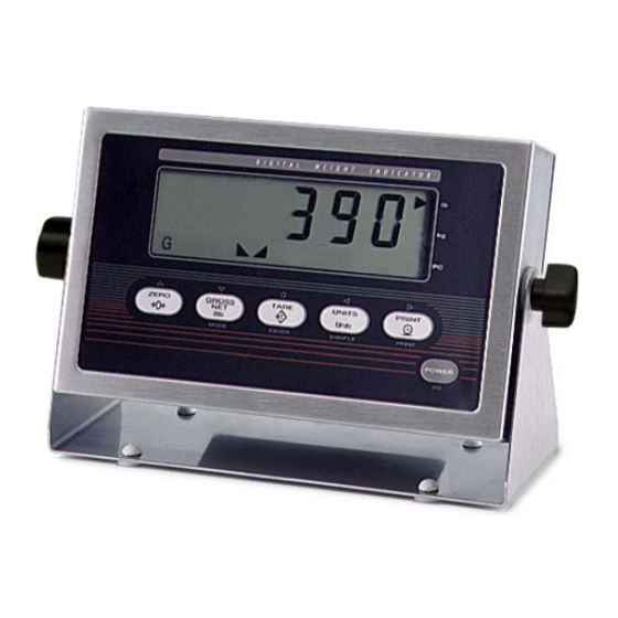
Page 6: Front Panel Keypad
Front Panel Keypad Figure 1-1 shows the IQ plus 390-DC front panel keys and the key functions assigned in normal mode. The symbols shown above the keys in Figure 1-1 (representing up, down, enter, left, right) describe the key functions assigned in setup mode. In setup mode, the keys are used to navigate through menus, select digits within numeric values, and increment/decrement values. -
Page 7: Indicator Operations
Gross mode Standstill Tare in system Net mode Center of zero Low battery Figure 1-2. IQ plus 390-DC Display Annunciators Indicator Operations 1.4.5 Remove Stored Tare Value Basic IQ plus 390-DC operations are summarized below: 1. Remove all weight from the scale and wait for the standstill annunciator ( 1.4.1... -
Page 8: Installation
J3, then set the backplate and serial communications connectors. assembly aside. Cable Connections The IQ plus 390-DC provides two cord grips for cabling into the indicator: one for the load cell cable, the other for serial communications. Serial communications Battery cover... -
Page 9: Cable Grounding
Once cables are attached, reconnect J2 to the header • Finish installation using cable mounts and ties to on the board. secure cables inside of indicator enclosure. The IQ plus 390-DC serial port supports full duplex RS-232 communications for connections to printers, NOTE: Install lockwashers first, against backplate, NOTE: Install lockwashers PCs, and other attached devices. -
Page 10: Enclosure Reassembly
Keypad Connector Battery Adapter Input Input Figure 2-3. IQ plus 390-DC CPU Board Enclosure Reassembly Battery Installation Once cabling is complete, position the backplate over To install or replace batteries, do the following: the enclosure, reconnect battery cable, and reinstall 1. -
Page 11: Ac Adapter
AC Adapter Board Removal The AC adapter can be used to provide power to the If you must remove the IQ plus 390-DC CPU board, indicator if battery power is low and AC power is use the following procedure: available. Use only the adapter supplied with the 1. -
Page 12: Replacement Parts
Replacement Parts Table 2-3 lists replacement parts for the IQ plus 390-DC, including all parts referenced in Figure 2-7 on page 9. Ref Number Description (Quantity) 49520 Battery cover thumb screws (4) 47939 Battery cover (1) 49557 Battery cover gasket (1) - Page 13 1/4X 29/2X 7/2X 9/2X 10/6X 11/8X 13/2X 15/4X 36/8X 25/2X 24/2X 40/2X 38/2X 27/4X Figure 2-7. IQ plus 390-DC Assembly Installation...
-
Page 14: Configuration
Configuration Methods mode. The IQ plus 390-DC indicator can be configured by 4. Start the Revolution program. using the front panel keys to navigate through a series Figure 3-1 shows an example of one of the Revolution of configuration menus or by sending commands or... -
Page 15: Front Panel Configuration
Front Panel Configuration The IQ plus 390-DC indicator can be configured using a series of menus accessed through the indicator front panel when the indicator is in setup mode. Table 3-1 summarizes the functions of each of the main menus. -
Page 16: Menu Structures And Parameter Descriptions
(see Figure 3-4). Menu Structures and Parameter Descriptions The following sections provide graphic representations of the IQ plus 390-DC menu structures. In the actual menu structure, the settings you choose under each parameter are arranged horizontally. To save page space, menu choices are shown in vertical columns. -
Page 17: Configuration Menu
3.2.1 Configuration Menu CONFIG FORMAT CALIBR SERIAL PROGRM PFORMT VERS XXXXXXX XXXXXXX GRADS ZTRKBN ZRANGE MOTBAN OVRLOA SMPRAT FS+2% 15HZ 1.9% 10000 0.5D 100% FS+1D 30HZ number FS+9D 3.75HZ 7.5HZ DIGFL1 DIGFL2 DIGFL3 DFSENS DFTHRH TAREFN 8OUT NONE BOTH 16OUT NOTARE 32OUT PBTARE... - Page 18 Tare function. Enables or disables push-button and keyed tares. Possible values are: NOTARE BOTH: Both push-button and keyed tares are enabled PBTARE NOTARE: No tare allowed (gross mode only) KEYED PBTARE: Push-button tares enabled KEYED: Keyed tare enabled Table 3-2. Configuration Menu Parameters (Continued) IQ plus 390-DC Installation Manual...
-
Page 19: Format Menu
3.2.2 Format Menu CONFIG XXXXXXX FORMAT CALIBR SERIAL PROGRM XXXXXXX PFORMT VERS PRIMAR SECNDR DSPRAT DECPNT DSPDIV UNITS DECPNT DSPDIV UNITS MULT 250MS 500MS 888888 750MS 88888.8 0.45359 888880 888888 number 1500MS 888880 2500MS 8.88888 8.88888 1SEC 88.8888 88.8888 888.888 2SEC 888.888 NONE... - Page 20 See Section 8.5 on page 36 for a list of multipliers. keyboard To toggle between primary and secondary units, press the UNITS key. Table 3-3. Format Menu Parameters (Continued) IQ plus 390-DC Installation Manual...
-
Page 21: Calibration Menu
3.2.3 Calibration Menu See Section 4.0 on page 22 for calibration procedures. CONFIG XXXXXXX FORMAT CALIBR SERIAL PROGRM XXXXXXX PFORMT VERS WZERO WVAL WSPAN REZERO *CAL* CAL* *CAL* Display and edit Display and edit Press Enter to Display and edit test weight value span calibration remove offset from... -
Page 22: Serial Menu
3.2.4 Serial Menu See Section 8.2 on page 32 for information about the IQ plus 390-DC serial data format. CONFIG FORMAT XXXXXXX CALIBR SERIAL PROGRM PFORMT XXXXXXX VERS BAUD BITS TERMIN EOLDLY STREAM 9600 8NONE CR/LF 000000 19200 7EVEN number... -
Page 23: Program Menu
3.2.5 Program Menu CONFIG XXXXXXX FORMAT CALIBR SERIAL PROGRM XXXXXXX PFORMT VERS PWRUPM STNDBY COUNT REGULA CONSNU CONSTU 000000 000000 NONE DELAY OIML number number number NTEP CANADA SBYDLY LSTMOD ACCESS SPLSIZ DSABLE number ENABLE Figure 3-9. ProgramMenu PROGRM Menu Parameter Choices Description... - Page 24 With access disabled, pressing the GROSS/NET (MODE) key toggles between gross and net modes only. SPLSIZ Sample size. Specify the default sample size used for counting scale operations. Sample size can be changed in counting mode during sample acquisition. Table 3-6. Program Menu Parameters (Continued) IQ plus 390-DC Installation Manual...
-
Page 25: Print Format Menu
3.2.6 Print Format Menu See Section 7.0 on page 29 for information about custom print formatting. CONFIG XXXXXXX FORMAT CALIBR SERIAL PROGRM XXXXXXX PFORMT XXXXXXX VERS GFMT NFMT CFMT Press to insert a space Same as GFMT before the active character Display first 6 Scroll left in format string Scroll right in format string... -
Page 26: Calibration
Calibration ™ The IQ plus 390-DC can be calibrated using the front panel, EDP commands, or the Revolution configuration utility. Each method consists of the following steps: • Zero calibration • Entering the test weight value • Span calibration •... -
Page 27: Edp Command Calibration
EDP Command Calibration 3. Place test weights on the scale and use the WVAL command to enter the test weight To calibrate the indicator using EDP commands, the value in the following format: indicator EDP port must be connected to a terminal or WVAL=nnnnnn<CR>... -
Page 28: Edp Commands
EDP Commands The IQ plus 390-DC indicator can be controlled by a personal computer or remote keyboard connected to Command Function the indicator EDP port. Control is provided by a set of EDP commands that can simulate front panel key... -
Page 29: Reporting Commands
RESETCONFIGURATION command is run. DUMPALL List all parameter values VERSION Write IQ plus 390-DC software version 5.1.4 Parameter Setting Commands Parameter setting commands allow you to display or Reset the indicator change the current value for a particular configuration Write current displayed weight with units parameter (Tables 5-3 through Table 5-8). - Page 30 Default sample size 5, 10, 20, 50, 100 REGULAT Regulatory compliance NONE, OIML, NTEP, CANADA CONSNUM Consecutive number 0–999 999 CONSTUP Consecutive number start-up value 0–999 999 Unit identifier 0–999 999 Table 5-7. PROGRM EDP Commands IQ plus 390-DC Installation Manual...
-
Page 31: Normal Mode Commands
DUMPALL EDP command to • When downloading configurations that include the indicator. The IQ plus 390-DC responds by sending changed serial communications settings, edit the all configuration parameters to the PC as ASCII- data file to place the serial communications formatted text. -
Page 32: Counting Operations
Counting Operations Sample Acquisition Mode The IQ plus 390-DC provides a piece count mode that allows the indicator to serve as a portable counting Sample acquisition mode is used to select the sample scale. In piece count mode, the indicator display... -
Page 33: Print Formatting
<N>, and <T>). indicator front panel (PFORMT menu), EDP ™ commands, or the Revolution configuration utility to The default IQ plus 390-DC print formats are shown customize the print formats. in Table 7-2: Print Formatting Commands Format Default Format String... -
Page 34: Using The Edp Port
IQ plus 390-DC front panel (see the ASCII character chart on page 33) and are shown as blanks. The IQ plus 390-DC can send or receive any ASCII character; the character printed depends on the particular ASCII character set implemented for the receiving device. -
Page 35: Using Revolution
7.2.3 Using Revolution The Revolution configuration utility provides a print formatting grid with a tool bar. The grid allows you to construct the print format without the formatting commands (<NL> and <SP>) required by the front panel or EDP command methods. Using Revolution, you can type text directly into the grid, then select weight value fields from the tool bar and place them where you want them to appear on the printed ticket. -
Page 36: Appendix
Appendix Error Messages The IQ plus 390-DC provides a number of front panel error messages to assist in problem diagnosis. Table 8-1 lists these messages and their meanings. Error Message Description Solution ADCERR A/D not responding Call Rice Lake Weighing Systems (RLWS) Service. -
Page 37: Ascii Character Chart
Use the decimal values for ASCII characters listed in Tables 8-2 and 8-3 when specifying print format strings on the IQ plus 390-DC PFORMT menu. The actual character printed depends on the character mapping used by the output device. The IQ plus 390-DC can send or receive any ASCII character value (decimal 0–255), but the indicator display is limited to the set described in Section 8.4 on page 35. - Page 38 Å » ∩ É ≡ ± æ ≥ Æ ô ≤ ö ⌠ ò ⌡ ÷ û ù ≈ ÿ ° Ö • Ü ¢ £ ¥ ƒ Table 8-3. ASCII Character Chart (Part 2) IQ plus 390-DC Installation Manual...
-
Page 39: Front Panel Display Characters
Front Panel Display Characters Figure 8-2 shows the 7-segment LCD character set used to display alphanumeric characters on the IQ plus 390- DC front panel. " < & > Figure 8-2. IQ plus 390-DC Display Characters Appendix... -
Page 40: Conversion Factors For Secondary Units
Conversion Factors for Secondary Units The IQ plus 390-DC has the capability to mathematically convert a weight into many different Primary Unit x Multiplier Secondary Unit types of units and instantly display those results with a press of the UNITS key. -
Page 41: Digital Filtering
Digital Filtering The IQ plus 390-DC uses averaged digital filtering to reduce the effect of vibration on weight readings. Adjustable threshold and sensitivity functions allow quick settling by suspending filter averaging, allowing the weight reading to jump to the new value. Figure 8-3 shows the digital filter parameters on the CONFIG menu. -
Page 42: Setting The Digital Filter Parameters
Test Menu functions are all on a single menu level, the GROSS/NET ( ) key has no function. Press ZERO ( ) key to exit test mode. Table 8-5 on page 39 summarizes the test menu functions. TEST A/DTST DEFLT PRTCFG Figure 8-5. Test Menu IQ plus 390-DC Installation Manual... -
Page 43: Software Revision History
ZERO GROSS TARE UNITS PRINT Units MODE ENTER SAMPLE PRINT POWER I / O TEST MODE KEY FUNCTIONS Figure 8-6. Front Panel Key Functions in Test Mode TEST Menu Function Description A/DTST Display A/D test Press and hold Enter key to display raw count from A/D converter. DEFLT Default parameters Press and hold the setup switch, then press the Enter key to reset configuration and calibration parameters to... -
Page 44: Specifications
300 bps; 8 data bits, no parity, or 7 data : 10 000 bits, even or odd parity : 10 000 Measurement Canada Approval AM-5300 Accuracy Class : 10 000 III HD : 20 000 IQ plus 390-DC Installation Manual... -
Page 45: Iq Plus 390-Dc Limited Warranty
IQ plus 390-DC Limited Warranty Rice Lake Weighing Systems (RLWS) warrants that all RLWS equipment and systems properly installed by a Distributor or Original Equipment Manufacturer (OEM) will operate per written specifications as confirmed by the Distributor/OEM and accepted by RLWS. All systems and components are warranted against defects in materials and workmanship for two years.
Need help?
Do you have a question about the IQ plus 390-DC and is the answer not in the manual?
Questions and answers