Table of Contents
Advertisement
Quick Links
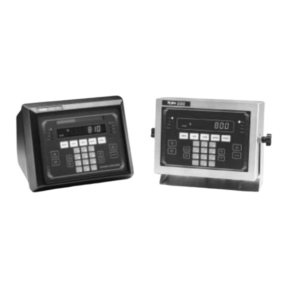
Rice Lake IQ Plus 800-3A
Digital Weight Indicator
A l l t r a d e m a r k s , b r a n d n a m e s , a n d b r a n d s a p p e a r i n g h e r e i n a r e t h e p r o p e r t y o f t h e i r r e s p e c t i v e o w n e r s .
• C r i t i c a l a n d e x p e d i t e d s e r v i c e s
• I n s t o c k / R e a d y - t o - s h i p
Artisan Scientific Corporation dba Artisan Technology Group is not an affiliate, representative, or authorized distributor for any manufacturer listed herein.
Limited Availability
Used and in Excellent Condition
Buy Today!
https://www.artisantg.com/78302-1
• We b u y y o u r e x c e s s , u n d e r u t i l i z e d , a n d i d l e e q u i p me n t
• F u l l - s e r v i c e , i n d e p e n d e n t r e p a i r c e n t e r
Advertisement
Table of Contents

Related Manuals for Rice Lake IQ plus 800-3A


Summary of Contents for Rice Lake IQ plus 800-3A
- Page 1 Rice Lake IQ Plus 800-3A Digital Weight Indicator Limited Availability Used and in Excellent Condition Buy Today! https://www.artisantg.com/78302-1 A l l t r a d e m a r k s , b r a n d n a m e s , a n d b r a n d s a p p e a r i n g h e r e i n a r e t h e p r o p e r t y o f t h e i r r e s p e c t i v e o w n e r s .
- Page 2 IQ plus 800/810 ® Digital Weight Indicators Version 3.1 Installation Manual 42100 Artisan Technology Group - Quality Instrumentation ... Guaranteed | (888) 88-SOURCE | www.artisantg.com...
- Page 3 Artisan Technology Group - Quality Instrumentation ... Guaranteed | (888) 88-SOURCE | www.artisantg.com...
-
Page 4: Table Of Contents
Course descriptions and dates can be viewed at www.rlws.com or obtained by calling 715-234-9171 and asking for the training department. Copyright © 2002 Rice Lake Weighing Systems. All rights reserved. Printed in the United States of America. Specifications subject to change without notice. - Page 5 5.3 Truck Modes ............................ 41 5.3.1 Using the Truck Modes ..........................42 5.3.2 Single-Transaction Tare Weights and IDs ....................43 5.3.3 Multiple Scales ............................43 5.4 Individual Scale Setup........................43 5.5 Using the TOTAL Channel ........................ 43 EDP Commands.......................... 45 6.1 The EDP Command Set ........................
- Page 6 9.13.1 2-Channel Relay Board..........................77 9.13.2 4-Channel Relay Board..........................77 9.14 Setpoint Digital Output Expander ....................78 9.15 IQ plus 810 4- and 16-Channel Relay Racks................... 79 9.16 Jetpak™ High Speed Option ......................82 9.17 Allen-Bradley Remote I/O Interface ....................83 9.18 Profibus Indicator Interface ......................
- Page 7 IQ plus 800/810 Installation Manual Artisan Technology Group - Quality Instrumentation ... Guaranteed | (888) 88-SOURCE | www.artisantg.com...
-
Page 8: About This Manual
A u t h o r i z e d d i s t r i b u t o r s a n d t h e i r employees can view or download this manual from the Rice Lake Weighing Systems distributor site at www.rlws.com... -
Page 9: Optional Features
Optional Features Table 1-1 lists some of the optional features available for the IQ plus 800/810 indicators, including references to pages in this manual for more information. See page 10 for information about wall- and panel-mounting options. Option Option PN Model See Page Rate of Change Function... -
Page 10: Front Panel Keys And Annunciators
Front Panel Keys and Annunciators The following section describes the front panel keys, annunciators, and display functions of the IQ plus 800/810 indicators. Numeric keypad The numeric keypad is used to enter numeric values, such as tare weights and ID numbers. - Page 11 DISP TARE In the normal weighing mode, displays the current weight in the tare register, if DISP TARE DISP TARE any, and lights the annunciator. In the truck in/out mode, key in a truck ID number and press DISP TARE .
- Page 12 SETPOINT Press to show defined setpoint values. When you first press this key, the display shows SP 1 two seconds, then switches to show the setpoint value. Each time you press , the SETPOINT POINT next defined setpoint is shown. You can change the setpoint value by keying in a number and pressing .
-
Page 13: Installation
Installation Power Connections Board Connections The IQ plus 800/810 can operate from either a 115 The main CPU board is connected to the power VAC or 230 VAC 3-wire power supply line at 50 or 60 supply/display board by two ribbon cables. The power Hz. - Page 14 DIGITAL I/O WIRING J4-10 +5 VDC J4-9 J4-8 J4-7 DIG IN 1 J4-6 DIG IN 2 J4-5 DIG IN 3 J4-4 DIG OUT 4 Battery J4-3 DIG OUT 3 Power Power Supply Display Board J4-2 DIG OUT 2 Ribbon J4-1 DIG OUT 1 Cable Display Driver...
-
Page 15: Board Diagrams
Board Diagrams Load Cell Wiring Figures 2-5 through 2-7 show major component Wire the analog input cable from the load cell or locations on the IQ plus 800/810 circuit boards. junction box to the removable connector and plug into the CPU board at J10 near the A/D module. If your 1 2 3 4 5 6 7 indicator was purchased after June 1, 1996, the A/D Load Cell Connector... -
Page 16: Serial Communications Wiring
Serial Communications Wiring pins together, and tying the transmit (B) and receive (B) pins together. Terminal block J7 on the CPU board connects both the EDP (Electronic Data Processing) port and the printer Digital I/O Wiring port. See Section 3.2.5 on page 30 for information about configuring the serial ports. -
Page 17: Wall- And Panel-Mounting
Wall- and Panel-Mounting T h e f o l l ow i n g s e c t i o n s d e s c r i b e w a l l - a n d panel-mounting procedures for the IQ plus 800/810 indicators. -
Page 18: Iq Plus 810 Wall Mount Kit
2.7.2 IQ plus 810 Wall Mount Kit 2.7.3 IQ plus 810 SS and HE Model Wall Mounting A wall mount kit is available for mounting the IQ plus If you are permanently mounting an SS or HE model 810 against vertical surfaces. The indicator mounting to a wall, Underwriters Laboratories (UL) requires plate both swivels and tilts for adjusting the viewing that you run the AC power cord in conduit and connect... -
Page 19: Iq Plus 800 Panel Mount Kit
2.7.4 IQ plus 800 Panel Mount Kit 6. Remove the standard bezel and gasket from the front of the indicator and replace with the Use the following procedure when panel mounting IQ larger bezel and gasket from the panel mount plus 800 indicators manufactured after September kit. -
Page 20: Configuration
Configuration To configure the IQ plus 800/810 indicators, the When the indicator is placed in setup mode, the word indicator must be placed in setup mode. The setup is shown on the display. The CONFIG menu CONFIG s w i t c h i s l o c a t e d o n t h e t o p e d g e o f t h e is the first of the main menus used to configure the vertically-mounted CPU board, near the middle of the indicator. -
Page 21: Edp Command Configuration
Revolution provides online help for each of its configuration displays. Parameter descriptions provided in this manual for front panel configuration can also be used when configuring the indicator using Revolution: the interface is different, but the parameters set are the same. 3.1.2 EDP Command Configuration The EDP command set can be used to configure the... -
Page 22: Menu Structures And Parameter Descriptions
To select a parameter, press SETPOINT CLEAR until the desired menu group appears on the display, DISP then press TIME/DATE to move down to the desired TARE POINT level. When moving down through the menus, the default setting appears first on the display. To change a default, scroll left or right through the various options TIME/ for that level. - Page 23 CONFIG Menu Parameter Choices Description Level 2 submenus SCALE 1–4 GRADS Specifies the analog input channel being configured. See level 3 submenus for ZTRKBND configuration choices. ZRANGE MOTBAND OVRLOAD DIGFLTR PWRUPMD Power up mode. In GO mode, the scale goes into operation immediately after a brief DELAY power up display test.
- Page 24 CONFIG Menu Parameter Choices Description FEATURE ACCUM Allows you to verify current feature status or to activate a feature. See the Level 3 parameter descriptions on page 18 for information about activating these features. PEAK PASSWRD DEFAULT RESET Press the down (TIME/DATE) key to reset configuration parameters to default values. This parameter is available only with software versions 3.13 and later.
- Page 25 CONFIG Menu Parameter Choices Description DIGFLT Digital filtering. Selects the digital filtering rate used to reduce the effects of mechanical vibration from the immediate area of the indicator. Choices indicate the number of A/D conversions per update that are averaged to obtain the displayed reading.
-
Page 26: Set Analog Menu
3.2.2 Set Analog Menu CONFIG XXXXXXX SET ALG FORMAT SETPNTS SERIAL P FORMT XXXXXXX DIG IN ALG OUT XXXXXXX BAR GRF XXXXXXX CALIBRT VERSION XXXXXXX CHANS TOTALS PULS IN RESOLUT FREQ ALGFLTR STANDRD 60 HZ 8 HZ P1>CH3 HIGH 50 HZ ENABLE P>CH3+4 2 HZ... -
Page 27: Format Menu
3.2.3 Format Menu CONFIG XXXXXXX SET ALG FORMAT SETPNTS SERIAL P FORMT XXXXXXX DIG IN XXXXXXX ALG OUT BAR GRF XXXXXXX CALIBRT VERSION XXXXXXX SCALE 1 SCALE 2 SCALE 3 SCALE 4 TOTAL DATE TIME UNITS SPNAME PRIMARY SECNDRY RATECHG same as SCALE 1 DSP DIV DEC PNT... - Page 28 FORMAT Menu Parameter Choices Description UNITS unit ID Allows customization of default units identifiers for displayed and printed weights. Default values (LB=pound; KG=kilogram; OZ=ounce; TN=ton; GR=gram; G=grain) can be modified using the procedure described for the P FORMT menu. Customized identifiers are listed in the UNITS subparameter values for primary, secondary, and ROC parameters.
- Page 29 FORMAT Menu Parameter Choices Description UNITS Specifies primary units for displayed and printed weight. Values are: LB=pound; KG=kilogram; OZ=ounce; TN=ton; GR=gram; G=grain. NONE Secondary Units DSP DIV Display divisions. Selects the value of minimum division size of the displayed weight. DEC PNT 888888.8 Decimal point location.
-
Page 30: Setpoints Menu
3.2.4 Setpoints Menu See Section 8.0 on page 59 for more information about configuring and using setpoints. CONFIG XXXXXXX SET ALG FORMAT SETPNTS SERIAL P FORMT XXXXXXX DIG IN ALG OUT XXXXXXX BAR GRF XXXXXXX CALIBRT VERSION XXXXXXX SETPT 1 SETPT 2–20 same as SETPT 1 BATCHNG AUTO... - Page 31 Batch setpoints PAUSE DELAY WAIT SS COUNTER AUTOJOG same as COUNTER same as PAUSE VALUE same as PAUSE VALUE ACCESS NAME DIGOUT number number NONE NONE 1 thru 16 0 thru 9 HIDE PSHTARE PSHPRNT ALARM PSHACCM SOURCE ACCESS NAME DIGOUT NONE NONE...
- Page 32 SETPNTS Menu Parameter Choices Description Level 2 submenus SETPNT 1–20 Specifies setpoint kind. Some setpoint kinds can be batch or continuous setpoints only. GROSSSP NET SP +REL SP –REL SP % REL SP PAUSE (Delay can also be called Timer Setpoint) DELAY WAIT SS COUNTER...
- Page 33 SETPNTS Menu Parameter Choices Description +REL SP VALUE Positive relative setpoint. Trips at a specific value above the referenced setpoint (RELNUM). PSHTARE PSHPRNT TRIP BANDVAL HYSTER ALARM PSHACCM PREACT PREVAL BATCH SOURCE ACCESS NAME DIGOUT RELNUM –REL SP same as Negative relative setpoint.
- Page 34 SETPNTS Menu Parameter Choices Description AUTOJOG VALUE Automatically jogs the previous filling operation. This check weighs the prior NET SP, GROSS ACCESS SP, or REL SP setpoint operation to be certain its value is still true in the standstill condition. If NAME the prior setpoint value is not still true in standstill, the prior operation will jog on for a selected DIGOUT...
- Page 35 SETPNTS Menu Parameter Choices Description PSHPRINT Sends the SPFMT print sequence when the setpoint has been satisfied. If PSHPRINT is set to WAITSS and the setpoint is satisfied, the print is done only when WAIT SS standstill is achieved. Since the PSHACCUM, and PSHTARE are done after the PSHPRINT, these functions also wait for standstill.
- Page 36 SETPNTS Menu Parameter Choices Description ACCESS Front panel access. Allows setpoint values to be viewed or changed from the front panel using the SETPOINT key. Selections are: HIDE ON: Setpoint values can be viewed or changed in operating mode. OFF: Setpoint value can be viewed in operating mode. HIDE: Setpoint value can be neither viewed nor changed in operating mode.
-
Page 37: Serial Menu
3.2.5 Serial Menu See Section 10.3 on page 87 for information about serial data formats supported by the IQ plus 800/810 indicators. CONFIG XXXXXXX SET ALG FORMAT SETPNTS SERIAL P FORMT XXXXXXX DIG IN ALG OUT XXXXXXX BAR GRF XXXXXXX CALIBRT VERSION XXXXXXX... - Page 38 SERIAL Menu Parameter Choices Description Level 2 submenus BAUD Specifies settings for baud rate, data bits, termination characters, end-of-line delay, and port BITS address used by the EDP port. TERMIN EOL DLY ADDRESS PRINTER BAUD Specifies settings for baud rate, data bits, termination characters, and end-of-line delay used by BITS the printer port.
- Page 39 SERIAL Menu Parameter Choices Description Level 3 Submenus Printer Port BAUD 4800 Printer port baud rate. Selects the transmission speed for the printer port. 2400 1200 19200 9600 BITS 7 ODD Selects number of data bits and parity of data transmitted from the printer port. 8 NONE 7 EVEN TERMIN...
-
Page 40: Print Format Menu
3.2.6 Print Format Menu See Section 7.0 on page 54 for information about custom print formatting. CONFIG XXXXXXX SET ALG FORMAT SETPNTS SERIAL P FORMT XXXXXXX DIG IN ALG OUT XXXXXXX BAR GRF XXXXXXX CALIBRT VERSION XXXXXXX GFMT NFMT TRWIN TRWOUT SPFMT same as GFMT... -
Page 41: Digital Input Menu
3.2.7 Digital Input Menu CONFIG XXXXXXX SET ALG FORMAT SETPNTS SERIAL P FORMT XXXXXXX DIG IN XXXXXXX ALG OUT BAR GRF XXXXXXX CALIBRT VERSION XXXXXXX DIGIN 1 DIGIN 2 DIGIN 3 BATSTRT BATRUN ZERO BATPAUS BATSTRT ACCUM BATPAUS TARE ACCUM CLR CN NT/GRS CLR CN... -
Page 42: Analog Output Menu
3.2.8 Analog Output Menu See Section 9.11 on page 73 for information about installing, configuring, and calibrating the analog output option. CONFIG XXXXXXX SET ALG FORMAT SETPNTS SERIAL P FORMT XXXXXXX DIG IN ALG OUT XXXXXXX BAR GRF XXXXXXX CALIBRT VERSION XXXXXXX ALGOUT1... -
Page 43: Bar Graph Menu
3.2.9 Bar Graph Menu See Section 9.7 on page 69 for information about installing and configuring the bar graph option. CONFIG XXXXXXX SET ALG FORMAT SETPNTS SERIAL P FORMT XXXXXXX DIG IN XXXXXXX ALG OUT BAR GRF XXXXXXX CALIBRT VERSION XXXXXXX TWNKL DIGOUTS... -
Page 44: Calibration Menu
3.2.10 Calibration Menu See Section 4.0 on page 38 for calibration procedures. CONFIG XXXXXXX SET ALG FORMAT SETPNTS SERIAL P FORMT XXXXXXX DIG IN XXXXXXX ALG OUT BAR GRF XXXXXXX CALIBRT XXXXXXX VERSION CHAN 1 CHAN 2 CHAN 3 CHAN 4 WEIGHT VOLTS same as CHAN 1... -
Page 45: Calibration
Calibration Before beginning weight calibration The procedures described in this section use the front Caution with test weights, turn off AC power to panel keys shown below to navigate through the all equipment controlled by setpoints Calibration menu, shown in Figure 4-1. or their associated digital outputs. - Page 46 reappears on the display. Repeat to verify that if necessary, or press DISP TARE a second the results are similar. Record this value as time to exit calibration and return to the W SPAN for channel 1 in Table 4-1. This is a first-level menus.
-
Page 47: Edp Command Calibration
EDP Command Calibration To calibrate the indicator using EDP commands, the indicator EDP port must be connected to a terminal or personal computer. See Section 2.5 on page 9 for EDP port pin assignments; see Section 6.0 on page 45 for more information about using EDP commands. -
Page 48: Operating Modes
Operating Modes Setup Mode Truck Modes Setup mode lets you access the configuration and The truck in/out modes handle multiple truck ID calibration parameters described in Sections 3.0 and numbers and tare weights. There are six modes which 4.0. allow you to combine features in various ways: The setup switch is near the middle of the board, at the Value edge. -
Page 49: Using The Truck Modes
Value swapping ensures that the lowest of two To select a truck in/out mode, move the setup switch weight values associated with a particular ID number to the CONFIG position. Press once to TIME/DATE is entered as the tare weight. For example, if a truck drop to the next level, then press CLEAR several times... -
Page 50: Single-Transaction Tare Weights And Ids
Using the TOTAL Channel lower weight is always printed as the tare weight. The TOTAL parameter allows the indicator to use, or not use, the summing capability for multiple-channel 5.3.2 Single-Transaction Tare Weights and IDs setups. Version 3.1 supports temporary tare weights for indicators configured to use stored IDs (TARE200 The total channel is disabled and cannot modes 3–6). - Page 51 Suppose the user has the following actual data: Other total channel settings are as follows: SCALE#1: When all the individual channels 2527.6 (2550 displayed) MOTION BAND are out of motion the total channel is out of motion. SCALE#2: 1658.1 (1658.1 displayed) The total channel display is calculated by rounding Zero tracking is done for the ZERO BAND...
-
Page 52: Edp Commands
EDP Commands The IQ plus 800/810 indicators can be controlled by a Command Function personal computer or remote keyboard connected to KTARE Press the TARE key the indicator EDP port. Control is provided by a set of EDP commands that can simulate front panel key KUNITS Press the UNITS key press functions, display and change setup parameters,... -
Page 53: Reporting Commands
6.1.2 Reporting Commands FIGURATION clears all calibration values and provides no OK response. Reporting commands (see Table 6-2) cause the indicator to send specific information to the EDP port. • When the debug mode is on, more These commands are accessible in both setup mode information is printed as a batch sequence is and normal operating mode. - Page 54 Command Description Values LOCKON Lock indicator front panel in operating — mode LOCKOFF Unlock indicator front panel in operating — mode For commands ending with “#x”, x is the channel number (1–4). Omitting the “#x” channel identifier causes the command to run against the current display channel.
- Page 55 Command Description Values BATCHNG Batching OFF, AUTO MANUAL SETPOINT Setpoint number number (1–20) KIND Setpoint type OFF, GROSSSP, NETSP, +RELSP, –RELSP, %RELSP, PAUSE, DELAY, WAITSS, COUNTER, AUTOJOG, COZ, INMOTON, INRANGE, –GROSS, –NET, BATCHPR, TIMER, CONCUR VALUE Value number BANDVAL Bandwidth value number HYSTER Hysteresis...
- Page 56 Command Description Values EDP.TERMIN EDP port line termination characters CR/LF, CR EDP.EOLDLY EDP port end-of-line delay number EDP.ADDRESS EDP port address number PRN.BAUD Printer port baud rate 300, 600, 1200, 2400, 4800, 9600, 19200 PRN.BITS Printer port data and parity bits 7ODD, 8NONE, 7EVEN PRN.TERMIN Printer port line termination characters...
-
Page 57: Transmit Weight Data Commands
Command Description Values WZERO#x Zero weight calibration actual value WSPAN#x Span weight calibration actual value WVAL#x Weight value calibration actual value VZERO#x Zero volts calibration (see NOTE) number VSPAN#x Span volts calibration (see NOTE) number VVAL#x Volts value calibration (see NOTE) 2, 3 (mV/V) For commands ending with “#x”, x is the channel number (1–4). - Page 58 BATSTATUS Command The BATSTATUS command is used to check the current status of various setpoint and batching conditions. BATSTATUS returns 14 bytes of status data as described in Table 6-17. BATSTATUS is principally used to provide status information to a controlling batch program when using the Remote I/O Interface option. Status information returned in bytes 3–12 is coded as ASCII characters @ (hex 40) through O (hex 4F);...
-
Page 59: Saving And Transferring Data
Translating ASCII Status Data ASCII Value Bit 3 Bit 2 Bit 1 Bit 0 Use the table at right to evaluate the ASCII character output for bytes 3 – 12 and determine which of the low order bits are set on. For example, if the Digital Output Status returned in bytes 8 –... -
Page 60: Downloading Configuration Data From Pc To Indicator
6.2.4 Transferring Configuration Data from If a supervisor switch is installed, place the indicator Indicator to Another in supervisor mode and press the key to save PRINT Configuration data can be transferred from one all setpoint data. indicator to another. Like downloading from a PC, this See Section 9.5 on page 67 for information about the procedure is useful when a number of indicators with supervisor switch. -
Page 61: Print Formatting
Print Formatting The IQ plus 800/810 has a formattable print function The current printout configuration can be checked or available as a standard feature. This feature allows the c h a n g e d a f t e r e s t a b l i s h i n g b i d i r e c t i o n a l demand print serial output to be customized to meet communications with the IQ plus 800/810. -
Page 62: Using The Front Panel
7.1.2 Using the Front Panel If you have no access to equipment used to communicate through the EDP port or are working at a site where such equipment cannot be used, you can change print format strings from the front panel of the indicator. You can access each of the ticket formats in the first level menu PFORMT. -
Page 63: Ticket Formats
Figure 7-2 shows an example of the Revolution print Command Description formatting grid. <NLn> n = number of termination characters (<CR> or <CR/LF>)* <SPn> n = number of spaces* <SU> Toggle weight data format (formatted/ unformatted)** * If n is not specified, 1 is assumed. **After receiving an SU command, the indicator will send unformatted data until the next SU command is received. -
Page 64: Truck Weigh-In And Weigh-Out Tickets
7.2.2 Truck Weigh-in and Weigh-out Tickets 7.2.3 Setpoint Push Print Ticket You can use the TRWIN and TRWOUT format strings When a setpoint push print is set (PSHRPNT to customize the truck weigh-in and weight-out parameter on the level SETPNTS menu), the gross tickets. -
Page 65: Extended Print Format Commands
Extended Print Format Commands Resetting ID, Consecutive Number, and Accumulator Values for Print You can specify the units identifier used to print Commands demand, truck, and push print tickets as shown in Table 7-4. Units are specified by adding a slash and ID, consecutive number, and accumulator values can the units identifier after the command. -
Page 66: Setpoints And Batch Processing
Setpoints and Batch Processing T h e I Q p l u s 8 0 0 / 8 1 0 i n d i c a t o r s p r ov i d e 2 0 See the menu charts and descriptions in Section 3.0 programmable setpoints, each with 20 unique for details on each parameter. - Page 67 Kind Description INRANGE In range. The digital output associated with this setpoint is activated when the scale is within capacity range. No value is required for this setpoint. –GROSS Negative gross weight. The digital output associated with this setpoint is activated when the gross weight reading is less than zero.
-
Page 68: Using Continuous Setpoints
Using Continuous Setpoints Other continuous setpoints, such as GROSSSP, NET SP, +REL SP, –REL SP, %REL SP, TIMER, and Continuous setpoints are free-running: the indicator CONCUR require that you enter a numerical value to constantly checks the input channel for the setpoint determine the trip point. -
Page 69: Front Panel Preact Value Access
Batch Status Messages Table 8-3 shows the status messages used to indicate interrupted batches. Batch sequence stopped by… Status message Batch sequence restarted by… BATPAUS DIGIN set low HELD BATPAUSE DIGIN set high PAUSE setpoint PAUSED BATSTRT DIGIN or BATSTART EDP command BATPAUSE EDP command STOPPED Emergency stop switch... -
Page 70: Defining Setpoint Names
… FORMAT SETPNTS … SPNAME SETPT 1 SETPT 20 … … NAME 0 NAME 9 NAME NAME PEAS • Specify up to ten ingredient names on the FORMAT menu SPNAME parameter • Use the setpoint NAME parameter to select the NAME x value used for the setpoint •... -
Page 71: Optional And Advanced Features
Optional and Advanced Features Accumulate Function Five accumulators are available with the accumulator software feature. One accumulator is provided for The accumulate function is used to add weight data to each channel, including the total channel. When the a register for later access by the user. The accumulator PRINT key is pressed, the accumulator corresponding can keep a running total of weights entered, either... -
Page 72: Setpoint Access
To print an accumulator you display the accumulator where is the accumulator number and is the aaaaaaa value and press the key. The following ticket updated accumulator value. PRINT will be sent out the print destination port: The ticket produced by the setpoint PSHACCM is not ACCUM #x aaaaaaa LB formattable. -
Page 73: Peak Hold Function
Peak Hold Function The peak hold function is used to determine, display, and print the greatest net weight read during a weighing cycle. Peak hold tracks only net weight and operates independently of the display. Other analog inputs or gross weight can be shown during peak hold function cycles;... -
Page 74: Passwords
Backdoor Password If you forget the CONFIG password and have no way to enter the CONFIG menu, call Rice Lake Weighing Systems. We can help you find a unique “back-door” password to enter the CONFIG menu. -
Page 75: Batching Switch
Batching Switch The following items describe the operation of the batching switch for indicators running Release 3.0 and The batching switch option comes as a complete unit Release 3.1 software: w i t h l eg e n d p l a t e , l o c k i n g s t o p bu t t o n , a n d run/start/abort 3-way switch. -
Page 76: Bar Graph
NOTE: In Release 3.0, the default value for DIGINs 1 When configuration is complete, use the setup switch and 2 is OFF; in Release 3.1, the default values are to place the indicator back in weighing mode. BATSTRT (DIGIN 1) and BATRUN (DIGIN 2). Initialize the batch by turning the 3-way switch to Always verify the digital input assignments before ABORT, then unlock the STOP button. - Page 77 Figure 9-6 shows the BAR GRF menu used to configure the bar graph feature. See Section 3.2.9 on page 36 for more information about configuring this feature. BAR GRF XXXXXXX TWNKL DIGOUTS GRAPH GRPHALL SP REF BAND SP1 – SP20 number Figure 9-6.
-
Page 78: Expanded Serial Communications
Expanded Serial Communications 9.8.1 Duplex 20 mA Current Loop The standard EDP port supports duplex RS-232 serial The expanded serial communications options provide and simultaneous output-only (simplex) 20 mA d u p l e x 2 0 m A c u r r e n t l o o p o r R S - 4 8 5 current loop communications. - Page 79 Table 9-2 shows the pin assignments for load cell connections on the expansion boards. MAIN CPU BOARD EXPANSION BOARD Channel J10 Pin Signal –EXCITATION +EXCITATION SHIELD –SENSE +SENSE –SIGNAL +SIGNAL –EXCITATION +EXCITATION SHIELD –SENSE +SENSE –SIGNAL +SIGNAL Table 9-2. Channel 3 & 4 Load Cell Pin Assignments Figure 9-8.
-
Page 80: Remote Keyboard
9.10 Remote Keyboard J3 Pin Description J3 Pin Description The remote keyboard connector provides a means of SETPOINT (Left) SCALE # connecting a remote keyboard to the IQ plus 810 ZERO GROSS/NET indicator. The front panel keyboard on the indicator TARE UNITS remains active with the remote keyboard attached. - Page 81 LOAD CELL INPUTS SETUP SWITCH CH-1 JP1JP2 CH-2 J10C J10B J10A ANALOG OUTPUT MODULE ANALOG OUTPUT MODULE A/D CONVERTER CHANNELS 3 & 4 A/D CONVERTER POS1 POS2 POS1 POS2 ANALOG OUTPUT ANALOG OUTPUT EPROM Figure 9-11. Analog Output Installed on Expansion Board Figure 9-10.
- Page 82 Analog Output Calibration The following values are used as constants, depending The following calibration procedure requires a on the type of output: multimeter to measure voltage or current output from • 15300 For 0–10 V output the analog output module. •...
-
Page 83: Multiple Scale Inputs
9.12 Multiple Scale Inputs The hardware choices necessary to add multiple channels allow several possible combinations of The standard IQ plus 800/810 has a single analog multiple channels. Either a single or a dual-channel input channel. The 800 can be expanded to 2 channels, input module can be mounted on the main board and a and the 810 to 2, 3, or 4. -
Page 84: 2-Channel Relay Board
9.13.1 2-Channel Relay Board This compact (2.5" x 3.0") output board allows two digital outputs to control 115 VAC or DC services that operate other equipment. Both outputs can be wired for normally-open (N.O.) or normally-closed (N.C.) operation. Relays activate on a logic low state. Relay outputs are rated at 3 amps at 115 VAC and 0.5 amps at 50 VDC. -
Page 85: Setpoint Digital Output Expander
9.14 Setpoint Digital Output Expander The setpoint digital output expander board mounts on standoffs on the component side of the main board There are four standard digital outputs on the main (see Figure 9-16). An 8-pin male terminal (J5 on the board designed primarily to be switch-closure outputs main board), plugs into a socket on the setpoint for controlling relays. -
Page 86: Iq Plus 810 4- And 16-Channel Relay Racks
9.15 IQ plus 810 4- and 16-Channel Relay Racks Relay racks can be mounted on standoffs or bolted to • On the desktop models, the relay rack is mounted on a pre-drilled plate which is the main mounting panel on IQ plus 810 models to installed behind the CPU board using the allow 5 VDC indicator signals to operate AC or DC supplied standoffs (see Figure 9-18). - Page 87 J4 CONNECTOR ON MAIN BOARD DIGOUT 1 AC OUTPUT 4 TO EQUIPMENT DIGOUT 2 OAC5 OUT DIGOUT 3 AC OUTPUT 3 DIGOUT 4 TO EQUIPMENT OAC5 OUT DIGIN 3 AC OUTPUT 2 DIGIN 2 TO EQUIPMENT OAC5 OUT DIGIN 1 AC OUTPUT 1 TO EQUIPMENT OAC5 OUT...
- Page 88 AC OUTPUT #16 TO EQUIPMENT DC DIGOUT #16 DC DIGOUT #15 AC OUTPUT #15 TO EQUIPMENT OAC5 OUT DC DIGOUT #14 OAC5 OUT AC OUTPUT #14 TO EQUIPMENT AC OUTPUT #13 TO EQUIPMENT DC DIGOUT #13 OAC5 OUT DC DIGOUT #12 AC OUTPUT #12 TO EQUIPMENT OAC5 OUT AC OUTPUT #11 TO EQUIPMENT...
-
Page 89: Jetpak™ High Speed Option
9.16 Jetpak™ High Speed Option The Jetpak version of the IQ plus 800/810 features an Software indicators also designate the unit as a update rate of 100 updates per second. This option can high-speed version. At startup, the unit runs through a be added after purchase to modify an existing unit, but lamp test, then displays the word FAST... -
Page 90: Allen-Bradley Remote I/O Interface
Figure 9-23 shows an example of the Remote I/O 36254. Interface used to connect an IQ plus 810 indicator to Contact Rice Lake Weighing Systems for the latest an SLC controller on an Allen-Bradley network. technical updates to the Remote I/O interface. -
Page 91: Appendix
10.0 Appendix 10.1 Error Messages If an error code appears on the display, use the information in Table 10-1 as a troubleshooting guide. If you cannot clear the error, call RLWS Service for assistance. Be sure to check the software version (VERSION menu). In older versions with multiple scale applications, the display blanks when any scale goes over or under range. -
Page 92: Ascii Character Chart
10.2 ASCII Character Chart Use the decimal values for ASCII characters listed in Tables 10-2 and 10-3 when specifying print format strings on the P FORMT menu. The actual character printed depends on the character mapping used by the output device. - Page 93 ASCII ASCII ASCII ASCII α Ç á ü í β é ó Γ π â ú ä ñ Σ à Ñ σ å ª µ τ ç º ê ¿ Φ ë Θ Ω è ¬ ï δ î ∞ ì...
-
Page 94: Data Formats
10.3 Data Formats If the initiating device address matches the port address of an IQ plus 800/810 listening on the RS-485 10.3.1 Continuous Output Serial Data Format network, that indicator responds. For example, with If continuous transmission is configured for the EDP demand outputs, or in response to a KPRINT or printer port (STREAM parameter on the SERIAL command, the responding indicator uses the format... -
Page 95: Conversion Factors For Secondary Units
10.4 Conversion Factors for Secondary Units T h e I Q p l u s 8 0 0 / 8 1 0 h a s t h e c a p a b i l i t y t o mathematically convert a weight into many different Primary Unit x Multiplier... -
Page 96: Filtering
10.5 Filtering A d va n c e d R AT T L E T R A P ® d i g i t a l fi l t e r i n g (selections shown with RT after the number in Finding the right filter settings takes both patience and Figure 10-5) indicate a mode that can be viewed as a experimentation. -
Page 97: Software Revision History
10.6 Software Revision History Setpoint Processing • Automatic reset for COUNTER setpoints Version 3.1 software for the IQ plus 800/810 is based • No limit to number of TIMER and CONCUR on Version 3.0, which is documented in the previous setpoints version of this manual, PN 30262. -
Page 98: Specifications
10.7 Specifications Analog Output Optional: fully isolated, voltage or current output,14-bit resolution. Power Voltage output: 0 –10 VDC Load resistance:1kΩ minimum Line Voltages 115 or 230 VAC (+10%/–15%) Current output: 4–20 mA Frequency 50 or 60 Hz External loop resistance: 500Ω maximum Power Consumption 12 VA with minimum configuration, 30 VA with all options... - Page 99 Enclosure Classification: NEMA 4X NEMA 4 810 HE/SS NEMA 4X Enclosure Materials: Stainless steel Die-cast zinc 810 HE Fiberglass Reinforced Polyester (FRP) 810 SS Stainless steel Certifications and Approvals NTEP CoC Number: 92-013 Accuracy Class: III/III L 10 000 Measurement Canada Approval: AM-4840 Accuracy Class:...
-
Page 100: Iq Plus 800/810 Limited Warranty
IQ plus 800/810 Limited Warranty Rice Lake Weighing Systems (RLWS) warrants that all RLWS equipment and systems properly installed by a Distributor or Original Equipment Manufacturer (OEM) will operate per written specifications as confirmed by the Distributor/OEM and accepted by RLWS. All systems and components are warranted against defects in materials and workmanship for two years.
Need help?
Do you have a question about the IQ plus 800-3A and is the answer not in the manual?
Questions and answers