
Related Manuals for Rice Lake IQ plus 210


Summary of Contents for Rice Lake IQ plus 210
- Page 1 IQ plus ® Digital Weight Indicator Version 1 Installation Manual August 31, 2022 PN 64640 Rev C...
- Page 2 All information contained within this publication is, to the best of our knowledge, complete and accurate at the time of publication. Rice Lake Weighing Systems reserves the right to make changes to the technology, features, specifications and design of the equipment without notice.
- Page 3 August 31, 2022 Established revision history Table i. Revision Letter History Technical training seminars are available through Rice Lake Weighing Systems. Course descriptions and dates can be viewed at www.ricelake.com/training or obtained by calling 715-234-9171 and asking for the training department.
-
Page 4: Table Of Contents
Downloading Configuration Data from PC to Indicator ..........24 Rice Lake continually offers web-based video training on a growing selection of product-related topics at no cost. - Page 5 Specifications ..................28 Technical training seminars are available through Rice Lake Weighing Systems.
- Page 6 IQ plus 210 Installation Manual Rice Lake continually offers web-based video training on a growing selection of product-related topics at no cost. Visit www.ricelake.com/webinars www.RiceLake.com Visit our website...
-
Page 7: Introduction
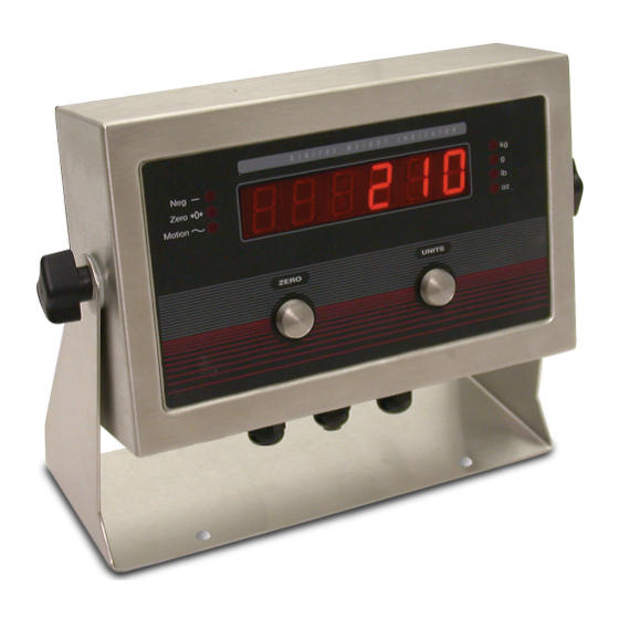
Overview The IQ plus 210 is a single-channel digital weight indicator housed in a NEMA 4X/IP66-rated stainless steel enclosure. The indicator front panel consists of a large (.8 in, 20 mm), six-digit, seven-segment LED display, seven LED annunciators, and two piezo switches used to zero the scale and select the displayed units. -
Page 8: Front Panel
Figure 1-1. IQ plus 210 Front Panel LED Annunciators The IQ plus 210 display uses a set of seven LED annunciators to provide additional information about the value being displayed: • annunciator lights to show that the displayed value is negative. -
Page 9: Installation
Installation Installation The IQ plus 210 digital weight indicator is designed for easy setup and installation. All models are pre-configured and weight calibrated before shipment, with the load cell connected to the indicator. For simple, standalone scale applications, hardware installation consists of attaching the indicator, mounting assembly, and bench scale, then leveling the scale. -
Page 10: Indicator
Cable Connections The IQ plus 210 provides three cord grips for cabling into the indicator: two for the power cord and load cell cabling, the third for communications and digital input cables. The free cord grip comes with a plug installed to prevent moisture from entering the enclosure. -
Page 11: Load Cells
DIGIN 1 P o w e r I n p u t Figure 2-2. IQ plus 210 CPU and Power Supply Board 2.3.2 Load Cells Wire the load cell cable from the load cell or junction box to connector J5 as shown in Table 2-2. If using 6-wire load cell cable... -
Page 12: Serial Communications
Figure 2-3. IQ plus 210 Enclosure Backplate 2.3.7 Board Removal If you must remove the IQ plus 210 CPU board, use the following procedure: 1. Disconnect power to the indicator. Remove backplate as described in Section 2.3 on page 2. Remove connections to J5 (load cell cable), J7 (serial communications), J2 and J3 (digital inputs), J4 and J6 (piezo button inputs), and J1 (setup switch). -
Page 13: Iq Plus 210 Indicator Repair Parts
Cord See Detail B To CPU J1 To Display Board Detail B Input Power J8 Detail A Ground Post Assembly Inside Bottom Plate Figure 2-4. IQ Plus 210 Indicator Parts Illustration © Rice Lake Weighing Systems ● All Rights Reserved... - Page 14 200 mA TR5 subminiature fuses, 115 VAC 53881 100 mA TR5 subminiature fuses, 230 VAC Table 2-4. IQ Plus 210 Repair Parts List For protection against risk of fire, replace fuses only with same type and rating fuse. WARNING www.RiceLake.com...
- Page 15 Figure 2-5. IQ Plus 210 Tilt Stand Assembly Item No. Part No. Description 29635 Tilt stand 42149 Tilt stand feet 15144 Nylon washers, 1/4x1x1/16 30342 Wing knobs Table 2-5. IQ Plus 210 Tilt Stand Assembly Parts List © Rice Lake Weighing Systems ● All Rights Reserved...
-
Page 16: Configuration
Configuration To configure the IQ plus 210 indicator, the indicator must be placed in setup mode. The setup switch is accessed by removing the large fillister head screw on the enclosure backplate. Insert a screwdriver into the access hole and press the switch to enter setup mode. -
Page 17: Edp Command Configuration
EDP Command Configuration The EDP command set can be used to configure the IQ plus 210 indicator using a personal computer, terminal, or remote keyboard. Like Revolution, EDP command configuration sends commands to the indicator serial port; unlike Revolution, EDP commands can be sent using any external device capable of sending ASCII characters over a serial connection. - Page 18 IQ plus 210 Installation Manual Most of the configuration menus have three or four levels. Figure 3-3 shows the general structure of the IQ plus 210 configuration menus. Note the following: • On the first (main) menu level, press to scroll through the menus. Pressing...
- Page 19 RIGHT starting with the leftmost digit. Figure 3-5. Editing Procedure for Numeric Values © Rice Lake Weighing Systems ● All Rights Reserved...
-
Page 20: Menu Structures And Parameter Descriptions
Menu Structures and Parameter Descriptions The following sections provide graphic representations of the IQ plus 210 menu structures. In the actual menu structure, the values under each parameter are arranged horizontally. To save page space, menu choices are shown in vertical columns. The factory default setting appears at the top of each column. -
Page 21: Format Menu
If LB/OZ is selected as the primary unit, DECPNT selections are 88 88.8 and 888 88. 888888 888880 8.88888 88.8888 88 88.8 888 88 DSPDIV Display divisions. Selects the minimum division size for the primary units displayed weight. Table 3-3. Format Menu Parameters © Rice Lake Weighing Systems ● All Rights Reserved... -
Page 22: Calibration Menu
IQ plus 210 Installation Manual FORMAT Menu Parameter Choices Description UNITS Specifies primary units for displayed and printed weight. Values are: LB=pound; KG=kilogram; OZ=ounce; G=gram; LB/OZ=pounds and ounces. LB/OZ Alternate Units (ALTUNT Parameter) Alternate units. Determines which units are displayed when the UNITS button is pressed. The value for the primary unit (selected on the PRIMAR parameter) is always ON. -
Page 23: Serial Menu
(including minus sign, if required) followed by lb and a space; and yyyy is the four-digit ounce weight (including decimal point) followed by oz. Table 3-5. Serial Menu Parameters © Rice Lake Weighing Systems ● All Rights Reserved... -
Page 24: Digital Input Menu
IQ plus 210 Installation Manual 3.2.5 Digital Input Menu CONFIG FORMAT CALIBR SERIAL XXXXXXX DIG IN XXXXXXX DEFLT VERS DIGIN1 DIGIN2 ZERO ZERO UNITS UNITS PRINT PRINT Figure 3-10. Digital Input Menu DIG IN Menu Parameter Choices Description Level 2 submenus DIGIN1 Specifies the function activated by digital inputs 1 and 2. -
Page 25: Calibration
Calibration Calibration The IQ plus 210 can be calibrated using the front panel, EDP commands, or the Revolution configuration utility. Each method ™ consists of the following steps: • Zero calibration • Entering the test weight value • Span calibration •... -
Page 26: Edp Command Calibration
IQ plus 210 Installation Manual 0 0 0 0 0 To edit numeric values, press the UNITS (RIGHT) button to select the leftmost digit. Each digit flashes when selected: Press ZERO (ENTER) increment the value of the selected digit; press the button to move right to the next digit. -
Page 27: Revolution ™ Calibration
8. When calibration is complete, the New Settings fields of the Weight Calibration display are filled in. Click Exit to save the new values and return to the Revolution main menu; to restore the previous calibration values, click Restore Settings. Figure 4-3. Revolution Calibration Display © Rice Lake Weighing Systems ● All Rights Reserved... -
Page 28: Edp Commands
EDP Commands The IQ plus 210 indicator can be controlled by a personal computer or remote keyboard connected to the indicator serial port. Control is provided by a set of EDP commands that can simulate front panel key press functions, display and change setup parameters, and perform reporting functions. -
Page 29: Parameter Setting Commands
Serial port data bits/parity 8NONE, 7EVEN, 7ODD EDP.TERMIN Serial port termination character CR/LF, CR EDP.ECHO Serial port echo command OFF, ON PRNFREQ Print frequency DEMAND, AUTO1, AUTO2, STREAM Table 5-6. SERIAL EDP Commands © Rice Lake Weighing Systems ● All Rights Reserved... -
Page 30: Normal Mode Commands
Saving and Transferring Data Connecting a personal computer to the IQ plus 210 EDP port allows you to save indicator configuration data to the PC or to download configuration data from the PC to an indicator. The following sections describe the procedures for these save and transfer operations. -
Page 31: Appendix
6.1.2 Using the XE EDP Command The XE EDP command can be used to remotely query the IQ plus 210 for the error conditions shown on the front panel. The XE command returns two 5-digit numbers in the format: xxxxx yyyyy where contains a decimal representation of any existing error conditions as described in Table 6-2. -
Page 32: Status Messages
IQ plus 210 Installation Manual Error Code Description Binary Value 1024 not assigned 0000 0100 0000 0000 2048 Internal overflow error 0000 1000 0000 0000 4096 not assigned 0001 0000 0000 0000 8192 not assigned 0010 0000 0000 0000 16384... -
Page 33: Continuous Output (Stream) Format
Appendix Continuous Output (Stream) Format Figure 6-1 shows the continuous output format sent to the IQ plus 210 EDP or printer port when the STREAM parameter (SERIAL menu) is set to either EDP or PRN. <STX> <POL> <wwwwwww> <UNIT> <G> <S>... -
Page 34: Specifications
IQ plus 210 Installation Manual Specifications IQ plus 210 Indicator Environmental Operating Temperature –10 to +40°C (legal); Power –10 to +50°C (industrial) Line Voltages 115 or 230 VAC Storage Temperature –25 to +70°C Frequency 50 or 60 Hz Humidity 0–95% relative humidity... - Page 36 Specifications subject to change without notice. Rice Lake Weighing Systems is an ISO 9001 registered company. 230 W. Coleman St. • Rice Lake, WI 54868 • USA U.S. 800-472-6703 • Canada/Mexico 800-321-6703 • International 715-234-9171 • Europe +31 (0)26 472 1319...
Need help?
Do you have a question about the IQ plus 210 and is the answer not in the manual?
Questions and answers