Table of Contents
Advertisement
Advertisement
Table of Contents

Related Manuals for Rice Lake IQ plus 310A


Summary of Contents for Rice Lake IQ plus 310A
- Page 1 ® IQ plus 310A Digital Weight Indicator Version 5.0 Installation Manual 22979...
- Page 2 Software Revision 5.0 — Summary of New Features Serial Data • Separate ticket formats allowed for the EDP port and Printer port • Printing in upper, lower, or mixed case letters from either port • Ticket printing from EDP port while Printer port is streaming in continuous mode •...
-
Page 3: Table Of Contents
REQUIRED EQUIPMENT FOR A/D CALIBRATION ..........38 7.3.2 A/D CALIBRATION PROCEDURE ................38 IQ plus 310A LIMITED WARRANTY ..................40 Copyright ©2001 Rice Lake Weighing Systems. All rights reserved. Printed in the United States of America. Specifications subject to change without notice. Version 5.0, August 2001... -
Page 4: Introduction
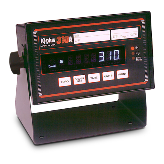
1 INTRODUCTION 1.1 OVERVIEW OF THE IQ plus 310A Designed to be installer- friendly, the IQ plus 310A can be configured and cali- brated entirely from the front IQ plus 31 0 panel without entering the = 10,000 III III L MADE IN USA case. -
Page 5: Panel Display Annunciators
1.2 PANEL DISPLAY ANNUNCIATORS BG — Entry Mode A tare weight has been acquired and stored by the system. A preset tare weight has been keyed in and entered via the EDP serial port. Solid rhombus: tare weight acquired by front panel key or via digital input. Blinking rhombus: Tare acquired or keyed in by EDP serial command. -
Page 6: Keyboard Functions
1.3 KEYBOARD FUNCTIONS The IQplus 310A’s five front panel keys have different functions for each of the two main modes of operation (Operate and Setup). Operate and Setup modes are accessed by the switch on the rear panel. Key functions for each mode become active when the switch is set to that mode. -
Page 7: Installation
2 INSTALLATION 2.1 OVERVIEW This section provides detailed installation procedures for the IQplus 310A hardware. The process is logical and straightforward when the steps are followed in the order given. 2.2 CHECKING THE ACCESSORY KIT When the IQplus 310A is unpacked, an accessory kit will be found in the packing box. The kit contains the following items: ITEM ITEM... -
Page 8: Making Power Connections
Communications Cable Load Cell Cable Power Power Receptacle Supply Board Cable Tie Load Cell Terminal Communications Block (J3) Cable Terminal Block (J4) Main Circuit Board FIGURE 3 – TOP VIEW WITH CASE REMOVED 2.4 MAKING POWER CONNECTIONS The IQplus 310A is an AC-powered unit. Note that there is no on/off power switch; the unit powers up when it is connected to the power source. -
Page 9: Connecting The Load Cell Cable
2.5 CONNECTING LOAD CELL CABLE The load cell cable connects to a plug-in terminal block (J3) on the main circuit board. When shipped, the IQplus 310A is configured for 4-wire load cell connections (JP1 and JP2 on main board are jumpered). If sense leads are to be used in a 6-wire connection, remove these two jumpers. -
Page 10: Installing Labels
Shield CAUTION RISK OF FIRE, REPLACE FUSES AS MARKED. 7 EXC- ELECTRIC SHOCK HAZARD. NEUTRAL CONDUCTOR -1 7 PROVIDED WITH OVERCURRENT PROTECTION. 6 EXC+ -2 6 TEST COMPONENTS BEFORE TOUCHING 5 SHLD RS232 5 F1, F2 4 SEN- UL / CSA IEC 127 20mA 4 3 SEN+... -
Page 11: Weight Unit Labels
Wiggle Capacity Strip left Capacity Flexible and right slightly while Strip Switch pushing it into loading slot. Panel Capacity Strip Loading Slot Loading Slot Rear of Front Panel Edge View FIGURE 9 – INSTALLING CAPACITY STRIP 2.7.2 WEIGHT UNIT LABELS The supplied weight unit labels can be applied over the existing "lb"... -
Page 12: Replacing The Case
2.8 REPLACING THE CASE Before installing the case, check the following: • All cables dressed and securely connected. • Jumpers JP1 and JP2 installed or removed correctly for your application. • Chassis cleaned of cut-off wires and insulation. • Capacity strip properly installed and tabs folded away from gaskets. Install the case as follows: Slide the case onto the unit, being careful that the ca-... - Page 13 From the rear of the panel, attach the two panel mount brackets to the sides of the indicator as shown in Figure 11. Indicator Case Panel Mount Bracket Sems Screw (1/4-20 X 3/8) FIGURE 11 – PANEL-MOUNT BRACKET INSTALLATION Mount each bracket to the case using a 1/4-20 X 3/8" pan-head sems screw with attached washer.
-
Page 14: Wall/Bench Mounting Procedure
2.9.2 WALL/BENCH MOUNTING PROCEDURE Mount the wall/bench mount bracket using appropriate hardware for the installation surface. Refer to Figure 13 for dimensions of the bracket and mounting holes. 0.70 6.00 4.83 3.00 0.265 DIA 0.92 FIGURE 13 – WALL/BENCH MOUNT BRACKET DIMENSIONS Peel off the protective paper from the adhesive surface of the two round neoprene gaskets and press the sticky surface of the gaskets to the inside surfaces of the tilt stand, centered on the holes needed for the installation (see Figure 14). -
Page 15: Power-Up
2.10 POWER-UP There is no power on/off switch for the IQplus 310A. Power is applied immediately when the line cord is connected to the supply. The normal operation of the IQplus 310A upon power-up in the default GO mode of the PWR UP parameter is to show a display check of all front panel LED figures for five seconds, then automatically shift to the GROSS weight mode. -
Page 16: Power-Up Display Error Messages
2.11 POWER-UP DISPLAY ERROR MESSAGES ERROR CODE PARAMETER CORRUPTED REMEDY ERR P1 Decimal Point Any of these codes ERR P2 Display Divisions displayed upon power- ERR P3 Units up indicates that a ERR P4 Digital Filter Stage 1 parameter value has ERR P5 Digital Filter Stage 2 been corrupted and is... -
Page 17: Configuration
3 CONFIGURATION 3.1 OVERVIEW The parameters which can be configured in the SETUP menu are described in detail in Section 3.3. They are shown in graphic form in Figure 17 as they actually appear on the display. This unit may be configured in the usual manner through the front panel keys, or via the EDP port with coded commands shown in Section 3.3 . - Page 18 SETUP DIG IN PRINTER ENTER GROSS ZERO TARE UNITS PRINT KEY FUNCTIONS IN SETUP MODE NOTE: Choices in bold type are the factory default settings. MODE BITS BAUD TICKET DEMAND STREAM 7 ODD 7 EVEN 8 NONE 1200 19200 9600 4800 2400 MODE BAUD BITS...
- Page 19 PTICKET ETICKET CALIBRT ZERO SPAN TW SPAN RE-ZERO 0010000 UP DOWN < > ENTER 100 (min.) to 60,000 (max.) < > < ENTER > < > ENTER ENTER FIELD 1 FIELD 2 FIELD 3 FIELD 4 NET TARE BLANK GROSS GROSS NET TARE BLANK TARE BLANK GROSS NET BLANK GROSS NET TARE...
-
Page 20: Menu Descriptions
3.3 MENU DESCRIPTIONS 3.3.1 SETUP MENU NOTE: Factory default settings are shown in bold type with a √ . The two-letter code in parentheses beneath each parameter name is the EDP command for that parameter. NAME/CODE DESCRIPTION CODE/VALUE GRADS Specifies number of full scale graduations. Value should be consis- 0 to 60,000 (GR) tent with legal requirements and environmental limits on the useful... - Page 21 3.3.1 SETUP MENU (CONTINUED) NAME/CODE DESCRIPTION CODE/VALUE 0 = 2 OUT DF SENS Filter cutout sensitivity. Selects the number of consecutive readings 1 = 4 OUT (FS) that must fall outside the threshold (see DF THRH) before digital √ 2 = 8 OUT filtering is ignored and the indicator jumps directly to the new value.
-
Page 22: Digital Input Menu
3.3.1 SETUP MENU (CONTINUED) CODE/VALUE NAME/CODE DESCRIPTION √ 0 = 250ms 5 = 2 sec UPDATE Display Update Rate: Selects the time between display updates. 1 = 500ms 6 = 2.5sec (UR) The motion detector can be made more sensitive to small 2 = 750ms 7 = 3 sec changes by increasing the update time, according to the 3 = 1 sec... -
Page 23: Edp Menu
3.3.3 EDP (ELECTRONIC DATA PROCESSING PORT) MENU CODE/SELECTION NAME/CODE DESCRIPTION MODE Selects the transmission mode of the EDP port. In DEMAND the 0 = STREAM √ (EM) port is quiet on power-up, but continuous data can be started and 1 = DEMAND stopped with the SX and EX commands. -
Page 24: Printer Menu
3.3.4 PRINTER MENU DESCRIPTIONS NAME/CODE DESCRIPTION CODE/SELECTION MODE Selects the transmission mode of the printer port. In TICKET 0 = STREAM mode, the port transmits data as formatted in the PTICKET (PM) √ 1 = TICKET Menu. In STREAM, the port transmits the selected data format 2 = DEMAND continuously, starting automatically on power-up. -
Page 25: Pticket And Eticket Format Menu
3.3.5 PTICKET AND ETICKET FORMAT MENU Two separate menus allow specification of the format of weight tickets—PTICKET for tickets sent to the printer port, and ETICKET for tickets transmitted via the EDP port. The line end characters to be sent are specified using the TERMIN parameters in each menu. The ticket format parameters in the table following determine the format of up to four fields of data printed on a weight ticket. -
Page 26: Functional Test And Configuration Reset
3.4 FUNCTIONAL TEST AND CONFIGURATION RESET A special TEST menu allows you to perform a functional test of the Display, Keyboard, EDP port and the two digital Inputs. Figure 19 describes the function performed by each key. A configuration reset function is also a part of the test menu. The TEST menu can only be accessed when the Operate/Setup Switch is in the SETUP position. -
Page 27: Calibration
4 CALIBRATION 4.1 CALIBRATING ZERO AND SPAN CALIBRT SPAN TW SPAN ZERO RE-ZERO Load test weights and adjust If Span adjustment is not Remove test weights Clear all weight from scale displayed value to match load necessary, return to from scale and press OPERATE mode now TARE to rezero UP | DOWN... -
Page 28: Fine-Tuning (Tweaking) Span And Re-Zero
RE-ZERO is designed to remove the weight offset of a chain or hook from the IQ plus 310A zero band. To perform the RE-ZERO, clear the platform of all weight, including the chains or hooks used. While the indicator is prompting RE-ZERO, press TARE (Enter). -
Page 29: Normal Operation
5 NORMAL OPERATION ZERO Press to return Gross weight display to zero. Zero indicator will light. GROSS Press to change between Gross G and Net N weight on display. Press to acquire tare. If tare is acquired by this method, the keyboard indicator lights. -
Page 30: In/Out Tare Mode
5.2 IN/OUT TARE MODE Once acquired with the TARE key, a tare value remains in memory for subsequent weighings until the TARE key is pressed again which erases the existing tare. A new tare can then be entered with the TARE key only when the scale is in the G mode. -
Page 31: Edp Remote Commands And Serial Port Operation
The IQ plus 310A responds with the value of the parameter if the command is an inquiry. The IQ plus 310A responds with “??” If the command string is invalid, or if trying to change a setup value while in OPERATE mode. -
Page 32: Edp Operating Commands
6.3 EDP OPERATING COMMANDS The following EDP 2-letter commands can be used to operate the scale. They are valid in OPERATE and SETUP modes except as noted. COMMAND DESCRIPTION OF FUNCTION Sets scale to zero. Valid only in Operate Mode. Tare in. -
Page 33: Serial Port Operation And Data Formats
6.4 SERIAL PORT OPERATION AND DATA FORMATS 6.4.1 SERIAL PORT OPERATION NOTES. 1. Serial input/output contention The IQplus 310A operates its serial ports in a preemptive receive mode. If the serial port starts receiving a command, any output in process to either the EDP port or the printer port is terminated immediately to avoid losing input data. - Page 34 6.4 SERIAL PORT OPERATION AND DATA FORMATS (CONTINUED) <STX> <POL> <wwwwwww> <UNIT> <G/N> <S> <TERM> Polarity: STX (02h) G for Gross <CR> or <Space> = Positive N for Net <LF> or < – > = Negative <CR> <LF> G = gram Weight: 7 digits, right-justified, dummy K = kilogram Status:...
- Page 35 6.4 SERIAL PORT OPERATION AND DATA FORMATS (CONTINUED) <STX> <SWA> <SWB> <SWC> <wwwwww> <tttttt> <EOL> <CHK> For T8142CK <CR> STX (02h) Status Word B Format Only: Optional Checksum Status Word A Status Word C Character 7-digit gross or net weight, right justified, padded with Six-digit tare weight.
- Page 36 <POL> <wwwwww> <SWA> <SWB> <TERM> Status Word B Polarity: <Space> = Positive < – > = Negative Status Word A <CR> or <LF> or <CR> <LF> Weight: 7 digits, right-justified, dummy zeroes, decimal point with no leading zeroes except for leading zero immediately preceding the decimal point.
-
Page 37: Appendix
7 APPENDIX 7.1 SPECIFICATIONS Analog Specifications Full Scale Input Signal 5 to 40 mV including deadload (initial load) Input Impedance 200 MΩ, typical Noise (Referred to Input) 0.3 µV p-p with 4-4-4 filter, maximum Internal Resolution Approximately 1,000,000 counts Display Resolution 60,000 dd Measurement Rate 50 meas/sec, typ. - Page 38 Power AC Option: Line Voltages 115 VAC (102-132) and 230 VAC (207-253) Frequency 50 or 60 Hz Power Consumption 12 VA maximum Fusing 115 VAC: 2 x 0.25A SB (UL/CSA) 5x20mm 230 VAC: 2 x T 125 mA (IEC127) 5x20mm Environmental OIML Meets OIML Document No.
-
Page 39: Digital Filtering
7.2 DIGITAL FILTERING 7.2.1 PRINCIPLES OF OPERATION The IQ plus 310A uses an averaging digital filter to reduce the effect of vibration on weight readings. Adjustable threshold and sensitivity functions allow quick settling by temporarily cutting out averaging so the reading immediately jumps to the new value being received. -
Page 40: A/D Calibration
7.3 A/D CALIBRATION This procedure is required following replacement of the A/D Converter (ADC) or the EEPROM. When the ADC and/or EEPROM are replaced, performing this procedure may be necessary in order for the ADC to operate. Implementing this procedure assures that the ADC will operate within its stability specifications. This procedure requires specialized test equipment and cables, and should be performed only by qualified personnel. - Page 41 Load Cell Connector EXC – EXC + EXC – Normal EXC + SHIELD SEN – Load Cell SEN + Simulator SIG – Calibrate SIG + Normal SIG – SIG + Reversed a. Load Cell Simulator Cable Comm & I/O 1 2 3 4 5 6 7 Connector Normal IN 1...
-
Page 42: Iq Plus 310A Limited Warranty
MODIFY THE TERMS OF THIS WARRANTY SHALL HAVE ANY LEGAL EFFECT UNLESS MADE IN WRITING AND SIGNED BY A CORPORATE OFFICER OF RLWS AND THE BUYER. © 2000 Rice Lake Weighing Systems, Inc. Rice Lake, WI USA. All Rights Reserved. • •...
Need help?
Do you have a question about the IQ plus 310A and is the answer not in the manual?
Questions and answers