
Related Manuals for Rice Lake IQ plus 310A XPCD


Summary of Contents for Rice Lake IQ plus 310A XPCD
- Page 1 IQ plus 310A XPCD ® Explosion Proof Digital Weight Indicator Technical/Service Manual 71784...
-
Page 2: Table Of Contents
3.2 IQ plus 310 XPCD Schematics ......................14 IQ plus 310A XPCD Limited Warranty ....................15 Copyright © 2002 Rice Lake Weighing Systems. All rights reserved. Printed in the United States of America. Specifications subject to change without notice. July 2002... - Page 3 IQ 310A XPCD Technical/Service Manual...
-
Page 4: About This Manual
This manual provides information on installation of the IQ plus 310A XPCD. The installer should be familiar with the National Electrical Code and RP 12.6 ( Recommended Practice ) requirements for installation of equipment in hazardous areas (NEC Article 504, Intrinsically Safe Systems ) published through the Instrument Society of America. - Page 5 The push buttons, rotary switches and sealing fittings are all attached to the enclosure via drilled and tapped holes in the enclosure. Just as with the flange, all threaded operators and fittings carefully control the flame path. IQ plus 310A XPCD Technical Service Manual...
- Page 6 Enlarged view below Explosion Propagation of gas due to pressure from an internal explosion The distance from the boundary of Cooling from the inside of the enclosure to the expansion of gas gasket is known as the Flame Path. (Boyle’s Gas Law) This distance must be at least 1”...
-
Page 7: Introduction
Introduction The IQ plus 310A XPCD is a single-channel digital weight indicator designed and approved to operate as an explosion proof system in a wide variety of scale and weighing applications. The indicator is housed in a cast aluminum explosion proof enclosure and can be safely used when the cover is properly installed and the sealing fittings are packed and cemented. -
Page 8: Front Panel Keypad And Annunciators
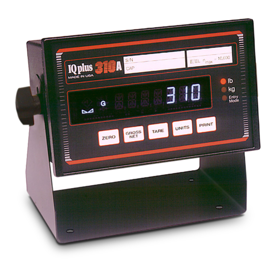
Front Panel Keypad and Annunciators Figure 1-1 shows the IQ plus 310A XPCD front panel. The IQ plus 310A XPCD front panel consists of 4 individual externally mounted buttons for gross/net, tare, units and print. Table 1-1 lists the button functions. -
Page 9: Installation And Wiring
Switches and Glass The glass and switches on the IQ plus 310A XPCD may look indestructible but they are not. If damaged in any way, the entire unit must be completely turned off at the source until it is replaced. The enclosure must be protected from blows and scrapes from passing equipment, falling objects, thick glues or resins, certain acids which eat aluminum, and other hazards which can break or damage the enclosure. -
Page 10: Sealoff Fittings
Sealoff Fittings The utmost care must be taken to completely seal the inside of the enclosure off from the outside world. To do this all wiring into and out of the enclosure must be in conduit using sealoff fittings between the enclosure and the conduit. -
Page 11: Cabling And Conduit Runs
Cabling and Conduit Runs 2.3.1 Cabling There are two types of cables that pass through a sealoff fitting, single conductor and multi conductor. Single Conductor Cabling Single conductor cables are typically redundant ground wires (used with resistive intrinsic safety barrier). Due to the nature of the method by which insulation is applied to wire, a single conductor wire (single or multi strand) can be considered gas tight. -
Page 12: Conduit Runs
2.3.2 Conduit Runs Conduit can be run either vertically or horizontally. But either way the conduit must be sealed properly to maintain the explosion proof integrity of the unit. The following paragraphs explain the proper way to install a conduit run and the sealing fittings. Horizontal Conduit Runs ®... -
Page 13: Ac Power Wiring
AC Power Wiring Electrical connections made in an explosion proof installation are made through rigid steel conduit through threaded openings in the back or sides of the enclosure and must comply with the National Electrical Code for installation of equipment in hazardous areas (NEC Article 504, Intrinsically Safe Systems ). Connect an electrically separate source of 115 VAC 60HZ to the terminals on the user wiring board marked L2, GND. -
Page 14: Intrinsic Safety Barriers
Intrinsic Safety Barriers The IQ plus 310A XPCD is designed to be used by personnel already trained and familiar with intrinsic safety barriers. They are designed to self destruct if a dangerous condition occurs. Note: If you are not trained to work on this equipment, stop. Call you scale dealer for assistance. -
Page 15: Load Cell Wiring
Load Cell Wiring The load cell wiring from the IQ plus 310A has been connected to the intrinsic safety barriers at the factory, (see Figure 2-4). The barriers are located in the bottom of the enclosure. Wire the load cell cable from the load cell or junction to terminal block TB4 (shown below). If using six-wire load cell cable (with sense wires), remove jumpers JP1 and JP2. -
Page 16: Serial Communications
Serial Communications The serial communications cable from the IQ plus 310 XPCD has been connected to the intrinsic safety barriers at the factory,(see Figure 2-4). The barriers are located in the bottom of the enclosure. Wire the serial communications cable to terminal block TB6 (shown below). +SENSE JUMPER -SENSE... -
Page 17: Appendix
Do not attempt to restart the unit until all damaged parts have been replaced and the unit has been tested. IQ plus 310 XPCD Schematics The following fold out pages contain wiring diagrams and system schematics for the IQ plus 310 XPCD indicator. IQ plus 310A XPCD Technical/Service Manual... -
Page 18: Iq Plus 310A Xpcd Limited Warranty
THE PROPERTY OF RICE LAKE WEIGHING SYSTEMS INC. AND IS CONFIDENTIAL. ALL THREADS TO BE CLASS 2 IT IS SUBMITTED AND MAY BE USED ONLY IN CONNECTION WITH RICE LAKE WEIGHING SYSTEMS' PROPOSAL AND/OR ITS CUSTOMERS' ORDERS. IT SHALL NOT... - Page 19 THE PROPERTY OF RICE LAKE WEIGHING SYSTEMS INC. AND IS CONFIDENTIAL. ALL THREADS TO BE CLASS 2 IT IS SUBMITTED AND MAY BE USED ONLY IN CONNECTION WITH RICE LAKE ALL DIMENSIONS APPLICABLE AFTER TREATMENT WEIGHING SYSTEMS' PROPOSAL AND/OR ITS CUSTOMERS' ORDERS. IT SHALL NOT BE...
- Page 20 THE PROPERTY OF RICE LAKE WEIGHING SYSTEMS INC. AND IS CONFIDENTIAL. ALL THREADS TO BE CLASS 2 IT IS SUBMITTED AND MAY BE USED ONLY IN CONNECTION WITH RICE LAKE 4. REMOVE BROWN, ORANGE, PURPLE, GREY, WHITE, AND PINK WIRES FROM BOTH ENDS.
- Page 21 UNITS TO BE IN INCHES ALL THREAD TO BE CLASS 2 IT IS SUBMITTED AND MAY BE USED ONLY IN CONNECTION WITH RICE LAKE ALL DIMENSIONS APPLICABLE AFTER TREATMENT WEIGHING SYSTEMS' PROPOSAL AND/OR ITS CUSTOMERS' ORDERS. IT SHALL NOT BE...
- Page 22 IQ plus 310A XPCD Limited Warranty Rice Lake Weighing Systems (RLWS) warrants that all RLWS equipment and systems properly installed by a Distributor or Original Equipment Manufacturer (OEM) will operate per written specifications as confirmed by the Distributor/OEM and accepted by RLWS. All systems and components are warranted against defects in materials and workmanship for one year.
Need help?
Do you have a question about the IQ plus 310A XPCD and is the answer not in the manual?
Questions and answers