Sungrow Logger1000B User Manual
Hide thumbs
Also See for Logger1000B:
- User manual (108 pages) ,
- Quick installation manual (30 pages) ,
- Quick installation manual (17 pages)

Subscribe to Our Youtube Channel
Related Manuals for Sungrow Logger1000B


Summary of Contents for Sungrow Logger1000B
- Page 1 User Manual Data Logger Logger1000A/Logger1000B Logger1000A/ Logger1000BData LoggerUser ManualLogger1000A_B-UEN-Ver19- 202211 M-H-001405 Logger1000A_B-UEN-Ver19-202211...
-
Page 3: All Rights Reserved
Software Licenses • It is prohibited to use data contained in firmware or software developed by SUNGROW, in part or in full, for commercial purposes by any means. • It is prohibited to perform reverse engineering, cracking, or any other operations that... -
Page 4: About This Manual
Please read this manual carefully before using the product and keep it properly at a place for easy access. All contents, pictures, marks, and symbols in this manual are owned by SUNGROW. No part of this document may be reprinted by the non-internal staff of SUNGROW without written authorization. - Page 5 Symbols This manual contains important safety instructions, which are highlighted with the following symbols, to ensure personal and property safety during usage, or to help optimize the product performance in an efficient way. Please carefully understand the meaning of these warning symbols to better use the manual. Indicates high-risk potential hazards that, if not avoided, may lead to death or serious injury.
-
Page 7: Table Of Contents
Contents All Rights Reserved .....................I About This Manual......................II 1 Safety Instructions ....................1 1.1 Unpacking and Inspection ................2 1.2 Installation Safety ...................2 1.3 Electrical Connection Safety................2 1.4 Operation Safety ....................3 1.5 Maintenance Safety ..................3 1.6 Disposal Safety ....................4 2 Product Description ..................5 2.1 Function Introduction ..................5 2.2 Performance Features ..................5... - Page 8 5.3.1 Connection to a single inverter .............20 5.3.2 Connection to multiple devices .............23 5.3.3 Connection to Smart Energy Meter ............23 5.3.4 Connection to Meteo Station ..............25 5.4 Connection to Background ................26 5.5 Connection to Micro-SIM................27 5.6 Connection to Power Box ................27 5.7 Cable Routing Requirements.................29 6 Commissioning ....................30...
- Page 9 7.10 System ......................46 7.10.1 Running Information ................46 7.10.2 System Maintenance .................46 7.10.3 Remote Maintenance ................47 7.10.4 Message Export ................48 7.10.5 System Time..................49 7.10.6 iSolarCloud..................50 7.10.7 IEC104 .....................50 7.10.8 MODBUS ..................54 7.10.9 Third-party portal................55 7.10.10 Port Parameter................55 7.10.11 MPLC .....................59 7.10.12 About .....................59 8 Grid Dispatching Function ................60 8.1 Function Description ..................60...
-
Page 11: Safety Instructions
Perform operations considering actual onsite conditions. • SUNGROW shall not be held liable for any damage caused by violation of general safety operation requirements, general safety standards, or any safety instruction in this manual. -
Page 12: Unpacking And Inspection
If there are problems with the above inspection items, do not install the device and contact your distributor first. If the problem persists, contact SUNGROW in time. Installation Safety Make sure there is no electrical connection before installation. -
Page 13: Operation Safety
• When the product is running, do not disassemble any parts of the product. Otherwise, electric shock may occur. Maintenance Safety Unauthorized modification or use of parts not sold or recommended by SUNGROW may result in fires and electric shocks. -
Page 14: Disposal Safety
• To avoid the risk of electric shock, do not perform any other maintenance operations beyond this manual. If necessary, contact SUNGROW for maintenance. Otherwise, the losses caused are not covered by the warranty. • If a fault occurs, only restart the device after the fault is cleared. Otherwise, the fault may expand, and the device may be damaged. -
Page 15: Product Description
Product Description Function Introduction The Logger1000 is a device used for data collection, power control, and protocol conversion for inverters and other PV equipment in the PV plant. The device is also integrated with communication gateway and plant O&M function. The Logger1000 is featured as flexible networking, auxiliary maintenance, and easy operation. - Page 16 2 Product Description User Manual The Logger1000 can be connected to iSolarCloud via the router or connected to the iSolarCloud via the WLAN or 4G network.
-
Page 17: Product Introduction
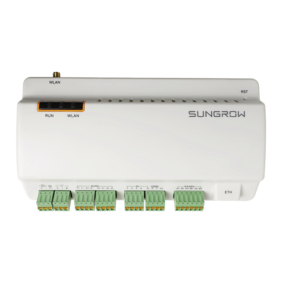
"table 5-1 Port description" Note: D* is 4G antenna mounting hole. The Logger1000A is provided with the hole while the Logger1000B is not. Specifically, refer to the actual product received. In the following, description is given by using the Logger1000A as an example. - Page 18 2 Product Description User Manual Indicator Indicator Description LED color LED status (print) No external power supply connected Running Slow flash (Green) Normal running Red/green indicator (RUN) Slow flash (Red) Device alarm Steady on (Red) Logger1000 running fault No data communication Steady on 4G connected successfully 4G indicator...
-
Page 19: Unpacking And Storage
Logger1000 from moving Length: 240mm Guide rail The Logger1000A is provided with the 4G antenna WLAN antenna mounting hole while Logger1000B is not. 4G antenna Specifically, refer to the actual product received. Converters the AC current into DC current Length Power box... -
Page 20: Identifying The Logger1000
Ensure that the device type is correct. • Check the device thoroughly and ensure there are no visible damages. If there are any problems, contact SUNGROW or the forwarding company. Only undamaged Logger1000 can be installed and commissioned. Before installation, ensure that: •... - Page 21 User Manual 3 Unpacking and Storage • The storage environment should be well ventilated, dry, and without any accumulated water. • Ambient temperature: -40℃ to +85℃; relative humidity: 0~95%, no condensation. • Take precautions to protect the device against damage due to harsh environment such as shock cooling, shock heating, and collision.
-
Page 22: Mechanical Mounting
Mechanical Mounting Respect all local standards and requirements during mechanical installation. Installation Location Selection Selecting an optimal installation location for the Logger1000 is critical to safe operation, long service life, and sound performance. Take the following requirements into account when selecting the installation location: •... -
Page 23: Installation Tools
User Manual 4 Mechanical Mounting Installation Tools Installation tools include but are not limited to the following recommended ones. If necessary, use other auxiliary tools on site. Installation Method The Logger1000 can be installed in the wall-mounting manner or guide rail-mounting manner, and users can select either one according to onsite condition. - Page 24 4 Mechanical Mounting User Manual step 2 Mark positions for drilling holes with a marker. step 3 Drill the holes with a drill according to the marked positions. Avoid drilling holes in the utility pipes and/or cables attached to back of the wall! Operation personnel should wear goggles and dust mask throughout the drilling process to avoid dust inhalation or contact with eyes.
-
Page 25: Guide Rail-Mounted Installation
User Manual 4 Mechanical Mounting step 6 Check and ensure that the Logger1000 is firmly installed. - - End 4.3.2 Guide Rail-Mounted Installation Secure the Logger1000 via the rail buckles (as shown in the figure below) on the back of it. step 1 Install and secure the guide rail at the appropriate location. -
Page 26: Installing Antenna
4 Mechanical Mounting User Manual step 3 Hook the Logger1000 into the guide rail from above and press down the lower part of the Logger1000 until it snaps into place. step 4 Push the buckle of the Logger1000 upwards to clamp the guide rail. step 5 Secure the terminal fasteners on both ends of the guide rail, to prevent the Logger1000 from moving. -
Page 27: Installing Power Box
User Manual 4 Mechanical Mounting Installing Power Box Mount the power box onto the concrete wall or metal surface according to onsite conditions. Secure the power box via the buckles (as shown in the figure below) on the back of it. step 1 Install and secure the power box guide rail at the appropriate location. - Page 28 4 Mechanical Mounting User Manual step 3 The installation of the power box and Logger1000 is completed. - - End...
-
Page 29: Electrical Connection
Electrical Connection Safety Instructions Incorrect cable connection may cause device damage or even personal injury. All cables must be intact, well insulated, appropriately dimensioned, and firmly connected. Port Introduction External wiring terminals are located at the bottom of Logger1000, and the wiring area is shown in the figure below. -
Page 30: Connection To Pv Devices
Devices in the PV system that can be connected to the Logger1000 include the inverter, Meteo Station, Smart Energy Meter, etc. 5.3.1 Connection to a single inverter The RS485 port of SUNGROW inverter is RS485 terminal block or RJ45 port. 5.3.1.1 RS485 terminal block connection Communication cable specification:... - Page 31 User Manual 5 Electrical Connection step 3 Connect the stripped cable to the RS485 ports of the Logger1000, as shown in the figure below. RS485A is connected to port A while RS485B is connected to port B. The RS485 communication cable must be the shielded twisted pair with the shielding layer single-point grounded.
- Page 32 5 Electrical Connection User Manual 5.3.1.2 RJ45 port connection Communication cable specification: Cable Type RJ45 communication cable Shielded twisted pair Ethernet cable step 1 Lead the RJ45 communication cable from the inverter to the wiring area of Logger1000. step 2 Strip the insulation layer of the communication cable with an Ethernet wire stripper, and lead the corresponding RS485A/B signal cables out.
-
Page 33: Connection To Multiple Devices
The addresses of devices on each RS485 bus must be different from one another and within the address range set for the Logger1000 (address range of residential inverters and string inverters manufactured by SUNGROW: 1-247; address range of third-party devices: 1-255). Otherwise, communication error will occur. - Page 34 Protocol Type Wiring Manufacture Sfere PD194E/Z Acrel PZ96-E3 Acrel DTSD1352 Modbus RTU " RS485 Connection" Weidmüller EM 610 SUNGROW DTSU666 Schneider IEM3255 " RS485 Connection" Modbus RTU UMG604, Janitza " Ethernet UMG104 Modbus TCP Connection" RS485 Connection The following figure shows the connection between the Logger1000 and the Smart Energy Meter.
-
Page 35: Connection To Meteo Station
User Manual 5 Electrical Connection Prepare two appropriate Ethernet cables. Connect the cable led from the Smart Energy Meter to a port of the core switch.Connect one end of the other Ethernet cable to another port of the core switch and the other end to the "ETH" port of the Logger1000. If there is no core switch connected on site, connect the cable led from the Smart Energy Meter directly to the "ETH"... -
Page 36: Connection To Background
5 Electrical Connection User Manual If multiple inverters are connected to the Logger1000 together with the Meteo Station, the Meteo Station should be connected on the very end of the daisy chain. AI Connection The following figure shows the connection between the Logger1000 and the Meteo Station. Connect the communication cable led from the Meteo Station to the AI port of the Logger1000. -
Page 37: Connection To Micro-Sim
User Manual 5 Electrical Connection figure 5-2 Connection to PV background system Default IP of the "ETH": IP12.12.12.12. - - End Connection to Micro-SIM Micro-SIM card size: 12mmx15mm. Support of hot plug of Micro-SIM. Connection to Power Box The Logger1000 supports DC24V power supply. Prepare two-core DC cable, three-core AC cable, and grounding cable before wiring. - Page 38 5 Electrical Connection User Manual Power cable wiring steps are as follows: step 1 Strip the cable jackets and insulation layers of the DC cable, AC cable, and grounding cable with a wire stripper by appropriate length. step 2 Insert the stripped DC cable into the "24V IN" and "24V OUT" ports of the Logger1000. Connect the DC cable led from the "24V OUT"...
-
Page 39: Cable Routing Requirements
User Manual 5 Electrical Connection The power source should meet limited power source or PS2 requirements. - - End Cable Routing Requirements Cables used in the system generally include power cables and communication cables. The communication cable needs to be routed away from the power cable, and the cables need to form a right angle at the intersection. -
Page 40: Commissioning
Commissioning Inspection before Commissioning Inspection item Result All cables are intact, well-insulated, and appropriately □ dimensioned All cables are connected correctly and firmly □ The polarity of the power supply cable is correct. The □ grounding cable is reliably grounded Commissioning Steps Step Result... - Page 41 Create new plant via the iSolarCloud App and check the □ iSolarCloud data for correctness. The auto search function is available for SUNGROW string inverters whose addresses are automatically allocated. Devices of other types, such as Smart Energy Meter and transformer, can be connected to Logger1000 via the adding device function.
- Page 42 6 Commissioning User Manual Use the iSolarCloud App to create a new plant. Users can directly scan the QR code on the front label of the Logger1000 or manually input the S/N to add communication equipment. For details, refer to the Quick Guidance of iSolarCloud App.
-
Page 43: Web Interface
WEB Interface Running Requirements Item Parameter Browser IE11 or later, Chrome65 or later, and Safari11 or later Min. resolution 1024*768 Login Steps The Web interfaces provided in this document are for reference only, and the actual ones may differ. Users of different types have different permissions. In the following, description is given by using the O&M permission as an example. -
Page 44: Ethernet Login
After login for the first time, it is recommended to change the password as soon as possible. Click O&M user→Modify password to change the password. With the login password forgotten, contact SUNGROW and provide the device S/ N as well as system time, to get the password. -
Page 45: Web Menu
User Manual 7 WEB Interface Designation Description Item Navigation menu Display main function modules of the Web Function display Display the current interface area Display the current alarm level and alarm number. Users can click the icons to enter the corresponding Alarm icon alarm interface Display the basic configuration steps of the... -
Page 46: Operation Procedure
Refer to the chapter "7.10.5 System Time". step 4 Automatically search the device. Devices that can be automatically searched, such as SUNGROW string inverter, can be added via the auto search function with addresses allocated automatically. Refer to the chapter "7.8.1 Device List". -
Page 47: Overview
User Manual 7 WEB Interface After all devices have been added, configure the forwarding service of the Logger1000, to ensure that the Logger1000 can forward the data to upstream devices. Refer to the chapter "7.10.6 iSolarCloud"~"7.10.9 Third-party portal". - - End Overview 7.6.1 General Information Click Overview→General information to enter the corresponding interface. -
Page 48: Device Monitoring
7 WEB Interface User Manual Device Monitoring Click Device Monitoring to enter the corresponding interface. Device information such as real-time values, DC data, initial parameter, protection parameter, general parameter, device instruction and device information can be viewed on this interface. 7.7.1 RealTime Values Realtime information such as power generation, device state, and active power can be viewed on this interface. -
Page 49: Protection Parameter
User Manual 7 WEB Interface 7.7.3.2 Batch setting step 1 Select the desired Country (region) and Grid type. step 2 Click Configure Synchronization. step 3 Select the desired devices in the pop-up device list, and click Save to achieve batch setting. - - End 7.7.4 Protection Parameter Click Device monitoring→Protection Parameters to enter the corresponding interface... -
Page 50: Device Information
Devices can be automatically searched and added. 7.8.1.1 Auto search The Auto Search function is used for SUNGROW string inverter to which addresses will be automatically allocated. step 1 Click Device→Device List to enter the corresponding interface. - Page 51 User Manual 7 WEB Interface 7.8.1.2 Export step 1 Click Device→Device List to enter the corresponding interface. step 2 Click the button to export the device list. - - End 7.8.1.3 Import step 1 Click Device→Device List to enter the corresponding interface. step 2 Click the button to export the device list.
- Page 52 7 WEB Interface User Manual 7.8.1.6 Add the Third-party Meter (Custom) step 1 Click Device→Device List to enter the corresponding interface. step 2 Click Add Device, select Meter option in the Device Type. step 3 Select the port (COM1/COM2/COM3/NET) that the meter is actually connected to in the Port.
- Page 53 User Manual 7 WEB Interface step 6 Select the points to be measured, click Read-back to read the information from the meter in real time to check the correctness of parameter setting. Only when the “Read-back Value” is consistent with the displayed value of the electric meter, the parameter setting of the measuring point is correct.
- Page 54 7 WEB Interface User Manual step 4 Select Others option in the Device Model. step 5 Select Custom option in the Configuration Method. Click Next to enter Configure Measuring Point the interface. table 7-2 Parameter description Description Parameter Refer to the device Modbus map, parse the order of the Byte Order read byte stream Beginning Address...
-
Page 55: Firmware Update
3 Click Confirm in the pop-up window, to delete the device. - - End 7.8.2 Firmware Update The Firmware Update function is used to upgrade the SUNGROW residential inverter and string inverter. step 1 Click Device→Firmware Update to enter the corresponding interface. -
Page 56: Afci Activation
7 WEB Interface User Manual 7.8.4 AFCI Activation step 1 Click Device→AFCI Activation to enter the corresponding interface. step 2 Check the devices that need to self-checking, click Self-checking and then Confirm on the pop-up window. The status of the self-checking device must be Enable. If the self-checking status is Disabled, you can click to set the self-checking status to Enable. -
Page 57: Remote Maintenance
User Manual 7 WEB Interface step 3 Select the type of logs to be exported, and click Confirm. - - End 7.10.2.3 Rebooting step 1 Click System→System Maintenance to enter the corresponding interface. step 2 Click Rebooting to enter the corresponding interface. step 3 A warning window will pop up, and click Confirm to continue the rebooting operation. -
Page 58: Message Export
7 WEB Interface User Manual • Users in Australia select Australian Server. • Users in other regions select the International Server. The remote maintenance address will change once the Logger1000 is restart. step 3 Click Save to enter the Remote Access interface. step 4 Enter the login password and click Confirm. -
Page 59: System Time
Click System→System Time to enter the corresponding interface. Method of setting system time: • When the option Inverter Timing is selected, SUNGROW inverter time will be synchronized with the time of Logger1000. • When the clock source is set to User Define, user can manually set the current system time and time zone in the following two manners: –... -
Page 60: Isolarcloud
7 WEB Interface User Manual Set the system time when using the Logger1000 for the first time. 7.10.6 iSolarCloud step 1 Click System→Transfer Configuration to enter the corresponding interface. step 2 Click the button to modify the forwarding configuration information of iSolarCloud. - - End The default iSolarCloud station is Chinese Server. - Page 61 User Manual 7 WEB Interface step 2 Click Client to enter the corresponding tab. - - End 7.10.7.1 White list setting When the option Enable White List is not selected, and the default IP address is "0.0.0.0", any background devices with valid IP address can access the Logger1000. When the option Enable White List is selected, and specified IP address is entered, only the device with the specified IP address can access the Logger1000.
- Page 62 7 WEB Interface User Manual table 7-7 Parameters of each equipment tab Data Coefficie- Data DataID State Invert Uint Type Name 1000 1000 On-grid Off-grid E-Daily Power On / Off P-Set Q-Set table 7-8 Description of parameter Description Parameter Value Data Type Data type Data type...
- Page 63 User Manual 7 WEB Interface figure 7-1 Device List tab parameters table 7-9 Description of parameter Description Parameter Sort devices, and only support moving the whole line for the device type corresponds one-to-one to its parameters in the same line Device Type Device type Number of COM port to which device connected,...
-
Page 64: Modbus
7 WEB Interface User Manual step 2 After editing the IEC104 forwarding point table, click Export→IEC104 CFG in the menu bar, and the prompt window will pop up. Convert the excel file into .xml file, where the .xml file and the excel file are in the same path. step 3 Click Add, to enter the Advanced Settings interface. -
Page 65: Third-Party Portal
4 Modify the configuration information and click Save. Set the FTP path and name it as "/FTP server directory". For example, for the name "/SUNGROW", / is the root directory, and SUNGROW is the directory where data is stored on the FTP server. - Page 66 7 WEB Interface User Manual 7.10.10.2 EyeW485 Click System →Port Parameter→EyeW485 to enter the corresponding interface, on which users can configure the master and slave nodes of the EyeW485 and send related operation instructions. EyeW485–H On this interface, uses can set the Country/Region, Frequency, and Array of the master node.
- Page 67 User Manual 7 WEB Interface table 7-11 EyeW485 Parameter Description Description Parameter Select the array number (red, blue, and green are colors of Array ID the COM indicator of the slave node). Enter the frequency point in the input box (it must be Frequency consistent with the frequency point of the master node).
- Page 68 7 WEB Interface User Manual 7.10.10.4 Mobile network Perform Mobile network setting on this interface. step 1 Click System→Port Parameter→Mobile Network to enter the corresponding interface. step 2 After modifying the APN, Username and Password, click to save the information. - - End 7.10.10.5 WiFi Perform WiFi setting on this interface.
-
Page 69: Mplc
User Manual 7 WEB Interface - - End 7.10.10.7 DI step 1 Click System→Port Parameter→DI to enter the corresponding interface. step 2 Set the initial status to NO or NC, and click the button to save the operation. - - End 7.10.11 MPLC step 1 Click System→MPLC, select the MPLC to be set, and click on the right to enter the... -
Page 70: Grid Dispatching Function
Multiple regulation manners can meet different regulation requirements. The Logger1000 can regulate the power output of the SUNGROW inverter, and the regulation mainly includes active power control and reactive power regulation. The Logger1000 can control device power output according to the local preset instructions. -
Page 71: Interface Description
User Manual 8 Grid Dispatching Function The corresponding power dispatching function is available only when the inverter supports active power control, power factor control, and reactive power regulation! For details, refer to the inverter user manual or consult the local retailer. Interface Description The Logger1000 is equipped with digital control interfaces and analog control interfaces for receiving digital instructions and analog instructions sent by the grid dispatching center. -
Page 72: Analog Control Interface
8 Grid Dispatching Function User Manual In Germany and some other European countries, the grid company uses the Ripple Control Receiver to convert the grid dispatching signal and send it in a dry contact manner, In this case, the plant needs to receive the grid dispatching signal in the dry contact communication manner. -
Page 73: Drm Control Interface
User Manual 8 Grid Dispatching Function table 8-2 Analog control interface signal definition Signal Definition 1+,1-,2+,2-,3+,3-,4+,4- 4 analog input channels The Logger1000 supports 4 inputs of 4~20mA analog currents or 4 inputs of 0~10V analog voltage. 8.2.3 DRM Control Interface The DRM control interface are located at the bottom of the Logger1000, as shown in the figure below. - Page 74 8 Grid Dispatching Function User Manual - - End 8.3.1.2 Remote power control When the instruction source is IEC104 or MODBUS TCP protocol, set the active control mode to Remote power control. step 1 Click Power control→Active power to enter the active power interface. step 2 Set the active control mode to Remote power control.
- Page 75 User Manual 8 Grid Dispatching Function Description Parameter If the adjustment does not reach the set target value, Adjustment ratio (%)* increase or decrease adjustment value according to the set adjustment ratio, so as to reach the target value. Time interval of delivering dispatching instructions Control cycle Parameter range: 5~60s Note: *Only when the control method is set to Closed-loop control, the parameter Select...
- Page 76 8 Grid Dispatching Function User Manual table 8-4 Parameter description Description Parameter Communication abnormality Communication is abnormal, and specified dispatch output (%) output value is delivered. Open-loop control:At the start time, the locally configured active instruction is sent to the power output port of the inverter, thereby implementing active power control.
- Page 77 User Manual 8 Grid Dispatching Function Description Parameter Enable: when feed-in power is detected, theLogger1000 will deliver start instruction to the inverter. Disable: when feed-in power is detected, Feed-in stop * theLogger1000 will not deliver start instruction to the inverter. Note: Never turn on the Enable switch arbitrarily! Generally, keep it in Disable state.
- Page 78 8 Grid Dispatching Function User Manual table 8-5 Parameter description Description Parameter Communication Communication is abnormal, and specified dispatch output abnormality output (%) value is delivered. Open-loop control: Active instruction controlled by AI is sent to the power output port of the inverter, thereby achieving active power control.
- Page 79 User Manual 8 Grid Dispatching Function 8.3.1.5 Digital Input When using the digital signal at the DI port of the Logger1000 as the dispatching input, set the active control mode to Digital input. step 1 Click Power control→Active power to enter the active power interface. step 2 Set the active control mode to Digital input.
-
Page 80: Reactive Power
8 Grid Dispatching Function User Manual Subsequent Operation Delete digital input manner: select a digital input manner that needs to be deleted, and click Clear data. 8.3.1.6 DRM mode When using the digital signal at the DI port (DI1 ~ DI4) of the Logger1000 as the dispatching input, set the active control mode to DRM mode. - Page 81 User Manual 8 Grid Dispatching Function 8.3.2.2 Remote Power Control When the instruction source is IEC104 or MODBUS TCP protocol, set the Reactive Control Mode to Remote power control. step 1 Click Power control→Reactive power to enter the reactive power interface. step 2 Set the Reactive Control Mode to Remote power control.
- Page 82 8 Grid Dispatching Function User Manual Description Parameter Forward: The reactive power direction of the inverter array displayed by the meter/transformer is the same as the actual reactive power direction. Reactive power direction* Backward: The reactive power direction of the inverter array displayed by the meter/transformer is opposite to the actual reactive power direction.
- Page 83 Note: *Only when the control method is set to Closed-loop control, the parameter Select energy meter is settable. When selecting an energy meter, the Logger used must be the one manufactured by SUNGROW. step 4 Add local power control manner Fill in Start time and Percentage(PF), and click Save.
- Page 84 8 Grid Dispatching Function User Manual table 8-9 Parameter description Description Parameter Communication Communication is abnormal, and specified dispatch output value abnormality output is delivered. Open-loop control: Reactive instruction controlled by AI is sent to power output port of the inverter, thereby achieving active power control.
- Page 85 User Manual 8 Grid Dispatching Function 8.3.2.5 Digital Input When using the digital signal at the DI port of the Logger1000 as the dispatching input, set the Reactive Control Mode to Digital input. step 1 Click Power control→Reactive power to enter the reactive power interface. step 2 Set the Reactive Control Mode to Digital input.
-
Page 86: Emergency Button
8 Grid Dispatching Function User Manual 8.3.2.6 Country Mode If the dispatching input must be the national power dispatching instruction, the Reactive Control Mode is set to Country mode. step 1 Click Power control→Reactive power to enter the reactive power interface. step 2 Set the Reactive Control Mode to Country mode. -
Page 87: Device Maintenance
Device Maintenance Due to the effect of ambient temperature, humidity, dust and vibration, the inner components of the Logger1000 will be aging and worn out. To ensure the system safety and maintain the efficiency of the Logger1000, it is necessary to carry out routine and periodic maintenance. All measures, which can help the Logger1000 to keep good working conditions, are within the maintenance scope. -
Page 88: Troubleshooting
The grounding cable must be grounded reliably. Otherwise, electric shock can cause personal injury! The common faults and troubleshooting is shown in the table below. If the problem still cannot be removed by following the instruction in this manual, please contact SUNGROW. - Page 89 Logger1000 Power-on fault 2. Power source failure 2. Replace the power source 3. Logger1000 fault 3. Contact SUNGROW 1. Check the RS485 1. The RS485 port is not communication cable connection; connected to any devices or the reconnect and tighten the cable if connection cable is loose or necessary.
- Page 90 9 Device Maintenance User Manual Fault Cause Corrective measures 1. Check the cable connection between the device and Logger1000; and reconnect and 1. Communication cable between tighten the cable if necessary. the device and the Logger1000 is 2. Power on the device if the The Logger1000 loose or disconnected.
-
Page 91: Appendix
10 Appendix 10.1 Technical Data Communication Max. number of devices 30 at most Communication ports RS485 interface 1 x RJ45, 10/100/1000Mbps Ethernet Digital input 5, Max. 24VDC Analog input 4, support 4~20mA or 0~10VDC Wireless Communication LTE(FDD): B1, B3, B5, B8 LTE(TDD): B38,B39, B40, B41 TD-SCDMA: B34, B39 4G Communication... -
Page 92: Dry Contact Wiring Cable
• The customer shall give SUNGROW a reasonable period to repair the faulty device. Exclusion of Liability In the following circumstances, SUNGROW has the right to refuse to honor the quality guarantee: • The free warranty period for the whole machine/components has expired. -
Page 93: Contact Information
The fault or damage is caused by installation, repairs, modification, or disassembly performed by a service provider or personnel not from SUNGROW. • The fault or damage is caused by the use of non-standard or non-SUNGROW components or software. •... - Page 94 Sungrow Power Supply Co., Ltd. www.sungrowpower.com...
Need help?
Do you have a question about the Logger1000B and is the answer not in the manual?
Questions and answers