Table of Contents
Advertisement
Advertisement
Table of Contents

Related Manuals for Sungrow Logger1000


Summary of Contents for Sungrow Logger1000
- Page 1 Logger1000 Data Logger User Manual Logger1000-UEN-Ver11-201903...
-
Page 3: Table Of Contents
Installation Flow..............13 Mechanical Installation ............14 Unpacking and Inspection ................14 Installation Location Requirements ............15 Installation Tools ....................16 Installing Logger1000 ..................16 5.4.1 Wall-Mounting ......................17 5.4.2 Guide Rail-Mounting ..................18 Installing Antenna ................... 19 Installing Power Box ..................20 Electrical Connection ............. - Page 4 6.3.1 Connection to Inverter ..................22 6.3.2 Connection to Energy Meter ................26 6.3.3 Connection to Meteo Station ................26 Connection to Background ................27 Connection to Power Supply................ 28 Cable Routing Requirements ............... 30 Commissioning ..............31 Inspection before Commissioning ............. 31 Commissioning Steps ..................
- Page 5 8.9.2 Firmware Update ....................44 8.9.3 Inverter Log ......................44 8.10 History Data ....................... 44 8.11 System ......................... 45 8.11.1 Running Information ..................45 8.11.2 System Maintenance ..................45 8.11.3 Remote Maintenance..................47 8.11.4 Message Export ....................47 8.11.5 System Time ......................48 8.11.6 Forwarding Configuration ................49 8.11.7 Interface .......................53 8.12 About ........................
- Page 6 11.3 Contact Information ..................72...
-
Page 7: About This Manual
1.2 Target Group This manual is applicable to technical personnel who are responsible for the installation, operation and maintenance of the Logger1000 and to users who need to perform daily operation. Readers should have some electrical knowledge and be familiar with electrical principles and electrical components. This manual does not cover the electrical connections of the inverter and the Meteo Station or related safety instructions. -
Page 8: Symbol Explanations
1 About this Manual User Manual 1.4 Symbol Explanations This manual contains important safety and operational instructions that must be accurately understood and respected during the installation and maintenance of the equipment. To ensure the optimum use of this manual, note the following explanations of the symbols used. - Page 9 User Manual 1 About this Manual (2) This device must accept any interference received, including interference that may cause undesired operation. Note: This product has been tested and found to comply with the limits for a Class B digital device, pursuant to Part 15 of the FCC Rules. These limits are designed to provide reasonable protection against harmful interference in a residential installation.
- Page 10 1 About this Manual User Manual antenna of a type and maximum (or lesser) gain approved for the transmitter by Industry Canada. To reduce potential radio interference to other users, the antenna type and its gain should be so chosen that the equivalent isotropically radiated power (e.i.r.p.) is not more than that necessary for successful communication.
- Page 11 User Manual 1 About this Manual Les utilisateurs de radars de haute puissance sont désignés utilisateurs principaux (c.-à-d., qu'ils ont la priorité) pour les bandes 5250-5350 MHz et 5650-5850 MHz et que ces radars pourraient causer du brouillage et/ou des dommages aux dispositifs LAN-EL.
-
Page 12: Safety Instruction
damage to the Logger1000 or other properties belong to the operators or the third party Therefore, the following safety instructions must be read and always kept in mind prior to any work. - Page 13 User Manual 2 Safety Instruction During Installation The Logger1000 can only be used as described in this manual. Altering the product without authorization or using spare parts not sold or recommended by SUMGROW may lead to fire, electric shock or other damages.
-
Page 14: Product Introduction
3.1 Function Description 3.1.1 Brief Product Introduction The Logger1000 is a device used for data collection, power control, and protocol conversion for inverters and other PV equipment in the PV plant. The device is also integrated with communication gateway and plant O&M function. -
Page 15: Networking Application
User Manual 3 Product Introduction 3.1.2 Networking Application As shown in the figure below, the Logger1000 can be connected to iSolarCloud via a switch. The Logger1000 can be connected to iSolarCloud via the router or connected to the iSolarCloud via the Wi-Fi. - Page 16 User Manual The Logger1000 supports various communication manners such as Wi-Fi. The Logger1000 is connected to various environment sensors, energy meters, Meteo Stations, and inverters in the PV power generation system via an RS485 bus. Users can access the Web interface via mobile phone or PC, on which parameter configuration and remote on-line upgrading can be performed.
-
Page 17: Appearance
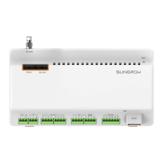
User Manual 3 Product Introduction 3.2 Appearance Views of the Logger1000 are shown in the following figure. Front view Bottom view Rear view Side view Fig. 3-1 Appearance Item Designation Description Indicator Indicate the running state of the Logger1000 Vent... -
Page 18: Dimensions
3 Product Introduction User Manual Slow flash of the communication indicator indicates data communication in process. If there has been no data communication with iSolarCloud for 10s, the indicator will keep steady on. 3.3 Dimensions Width (W) Depth (D) Height Fig. -
Page 19: Installation Flow
4 Installation Flow The following figure shows the overall installation flow of Logger1000. Start Unpacking and Inspection Installation location selection Mechanical installation Electrical installation Check before commissioning Running steps Ends Fig. 4-1 Installation flow Tab. 4-1 Description of the installation flow... -
Page 20: Mechanical Installation
4 sets, ST4.8X19, used for wall-mounting to fasten the bolt device on the concrete wall Terminal 2 sets, E/UK-1201442, fixed on the guide rail to prevent fastener the Logger1000 from moving Guide rail Length: 240mm WLAN antenna Converters the AC current into DC current... -
Page 21: Installation Location Requirements
Take the following requirements into account when selecting the installation location: With the ingress of protection IP 20, the Logger1000 can be installed only indoors. Ambient temperature range: -30℃ to +60℃. -
Page 22: Installation Tools
Wire stripper Wire clipper screwdriver Specification: Install ation Phillips Rubber mallet Crimping tool tools screwdriver 5.4 Installing Logger1000 The Logger1000 can be installed in the wall-mounting manner or guide rail-mounting manner, and users can select either one according to onsite condition. -
Page 23: Wall-Mounting
5 Mechanical Installation 5.4.1 Wall-Mounting Mount the Logger1000 onto the concrete wall or metal surface according to onsite conditions. Mount the Logger1000 onto the wall via the wall-mounting holes (as shown in the figure below) on the back of it. 83mm Mounting hole Fig. -
Page 24: Guide Rail-Mounting
Logger1000. Check and ensure that the Logger1000 is firmly installed. 5.4.2 Guide Rail-Mounting Secure the Logger1000 via the rail buckles (as shown in the figure below) on the back of it. -
Page 25: Installing Antenna
Buckle Install and secure the guide rail at the appropriate location. Step 1 Slight press down the recessed part under the buckle of Logger1000 with a Step 2 flat-head screwdriver or other similar tools to pull out the buckle outwards. -
Page 26: Installing Power Box
5 Mechanical Installation User Manual 5.6 Installing Power Box Mount the power box onto the concrete wall or metal surface according to onsite conditions. Secure the power box via the buckles (as shown in the figure below) on the back of Buckle Install and secure the power box guide rail at the appropriate location. -
Page 27: Electrical Connection
Incorrect cable connection may cause device damage or even personal injury. All cables must be intact, well insulated, appropriately dimensioned, and firmly connected. 6.2 Port Introduction External wiring terminals are located at the bottom of Logger1000, and the wiring area is shown in the figure below. WLAN WLAN AI/DI... -
Page 28: Connection To Pv Devices
) ports, the communication distance should not exceed 1,000m. 6.3 Connection to PV Devices Devices in the PV system that can be connected to the Logger1000 includes the inverter, Meteo Station, energy meter, etc. 6.3.1 Connection to Inverter Connection to a single inverter The RS485 port of SUNGROW inverter is RS485 terminal block or RJ45 port. - Page 29 A:15mm B:8mm...10mm Step 3 Connect the stripped cable to the RS485 ports of the Logger1000, as shown in the figure below. RS485A is connected to port A while RS485B is connected to port B. The RS485 communication cable must be the shielded twisted pair with the shielding layer single-point grounded.
- Page 30 Pin 3 and Pin 6 are used for communication. - Pin 3 to RS485- B - Pin 6 to RS485+ A Connect the communication cable to the RS485 port of the Logger1000 as Step 4 shown below. Logger1000 is connected to the inverter.
- Page 31 With an outdoor device connected to the Logger1000, it is recommended to connect an SPD to protect the Logger1000 from lightning damage. The Logger1000 allows for 3 inputs of RS485 buses and 30 devices at most. Different device types must connect to different RS485 communication ports of the Logger1000.
-
Page 32: Connection To Energy Meter
Serial port parameters of each device on the RS485 bus should be consistent with those of the Logger1000. The serial port parameters include baud rate, data bit, stop bit, and check bit. 6.3.2 Connection to Energy Meter It is recommended to use the energy meter whose communication protocol complies with DL/T645-2007 protocol or Modbus RTU protocol. -
Page 33: Connection To Background
6.4 Connection to Background The Logger1000 can be connected to the background of the PV system via the network port, and the communication protocol is standard Modbus TCP or IEC104. As a salve device, the Logger1000 can be accessed by multiple backgrounds and communicate by using the standard protocol. -
Page 34: Connection To Power Supply
Fig. 6-2 Connection to PV background system Default IP of the "ETH": IP12.12.12.12. 6.5 Connection to Power Supply The Logger1000 supports DC24V power supply. Prepare two-core DC cable, three-core AC cable, and grounding cable before wiring. Power cable specifications are shown in the table below. - Page 35 Connect the stripped grounding cable to the corresponding port of the Logger1000. Connect the DC cable led from the "24V IN" port of the Logger1000 to the Step 4 "DC 24V OUT" port of the power box. Connect the stripped AC cable to the "AC (100~277V)"...
-
Page 36: Cable Routing Requirements
User Manual AC (100~277V) DC 24V OUT Power eox Logger1000 6.6 Cable Routing Requirements Cables used in the system generally include power cables and communication cables. The communication cable needs to be routed away from the power cable, and the cables need to form a right angle at the intersection. -
Page 37: Commissioning
Power on the Logger1000. □ Check whether the indicators of Logger1000 normally flash. Connect the debugging PC to the "ETH" port of the Logger1000 □ via the network cable (default IP address of "ETH": 12.12.12.12). Log in the Web at 12.12.12.12 through the IE or Chrome browser. - Page 38 Use the iSolarCloud APP to create a new plant. Users can directly scan the QR code on the front label of the Logger1000 or manually input the S/N to add communication equipment. For details, refer to the Quick Guidance of iSolarCloud APP.
-
Page 39: Web Interface
1024*768 8.2 Preparation before Ethernet Login The IP address of the PC connected to the Logger1000 is the same as that of the Logger1000. The IP address is 12.12.12.X. For example, the IP address of the PC may set to 12.12.12.125, and the subnet mask is 255.255.255.0. -
Page 40: Wifi Login
"SG-A1234567890" is just used as an example. For actual wireless network, refer to the S/N on the label attached to the front side of the Logger1000. Enter the IP address 11.11.11.1 of the Logger1000 in the PC address bar to Step 2 enter the general user login interface. -
Page 41: Web Main Interface
Display the current alarm level and alarm number. Users Alarm icon can click the icons to enter the corresponding alarm interface Help Display the basic configuration steps of the Logger1000 Language menu Click the button to select the desired language User Display the current login user... -
Page 42: Web Menu
"6 Electrical Connection". Step 2 Configure serial ports of the Logger1000. After logging into the Web, first configure the serial ports of the Logger1000, to ensure that the Logger1000 can normally communicate with upstream devices. Refer to the chapter "8.11.7 Interface Step 3 Calibrate the system time. -
Page 43: Overview
8 Web Interface After all devices have been added, configure the forwarding service of the Logger1000, to ensure that the Logger1000 can forward the data to upstream devices. Refer to the chapter "8.9.1 Device List". Add the device. Refer to the chapter "8.9.1 Device List". -
Page 44: Current Alarms
8 Web Interface User Manual PV-plant value Information such as today yield, total yield, real-time active power, and number of offline devices can be viewed. Click the button "Exp." To view more information. Inverter real-time values Information on the inverter such as state, daily yield, active power, and reactive can be viewed. -
Page 45: Dc Data
User Manual 8 Web Interface Click the button to select the device type. On this interface, information such as power generation, device state, and active power can be viewed. 8.8.2 DC Data Click "Device Monitoring" -> "DC data" to view the corresponding information. On this interface, voltage and current information of multiple inputs of MPPTs and strings can be viewed. -
Page 46: Protection Parameter
8 Web Interface User Manual Initial parameters can be set in two manners: single setting and batch setting. Single setting: select the desired country (region) and grid type, and click "Setting" to set initial parameters for the single device. Batch setting: select the desired country (region) and grid type, and click "Configure synchronization". -
Page 47: Device Instruction
User Manual 8 Web Interface Select "Read-back", set register address, register number, and address type, and click the button "Read-back", to read the current value of the device. Select "Setting", set register address, data type, and set value, and click the button "Save", to set device parameters. -
Page 48: Device Maintenance
Logger1000 and configuring addresses for these devices. Devices can be automatically searched and added. Auto search The "Auto search" function is used for SUNGROW residential inverter and string inverter to which addresses will be automatically allocated. Click the button "Auto search", and the corresponding window pops up. Select an interface type, and click "Search". - Page 49 Click the button to import the modified device list to the Web. Only the address of SUNGROW residential inverter or string inverter can be modified. Add device Click "Add device", select a device type in the pop-up window, and fill in the information required.
-
Page 50: Firmware Update
Select the device to be deleted, click the button "Delete", and click "Confirm" in the pop-up window, to delete the device. 8.9.2 Firmware Update The firmware update function is used to upgrade the SUNGROW residential inverter and string inverter. Step 1 Click "Device"... -
Page 51: System
User Manual 8 Web Interface On this interface, operation logs of different users can be viewed. 8.11 System 8.11.1 Running Information Click "System" -> "Run-info" to enter the corresponding interface. Information such as wireless signal strength, WiFi AP IP, AI voltage, DI status can be viewed. - Page 52 Click "Rebooting" to enter the corresponding interface. A warning window will pop up, and click "Confirm" to continue the rebooting operation. Modification of the configuration parameters (port parameters and transfer configuration) of the Logger1000 will not take effect before the system is rebooted. Restore factory setting Click "Reset all settings"...
-
Page 53: Remote Maintenance
Tab. 8-1 Parameter description Remote maintenance switch state Description Not allow for remote maintenance on the Disabled Logger1000 Allow for remote maintenance on the Enable Logger1000 In case the remote maintenance switch is in the "Enable" state, the remote service address needs to be set. -
Page 54: System Time
When the clock source is set to "User define", user can manually set the current system time and time zone in the following two manners: Select "Use PC time" to synchronize the time of the Logger1000 with the time of the PC. ... -
Page 55: Forwarding Configuration
8 Web Interface The first time the Logger1000 is used, the system time must be configured. After the Logger1000 is powered off for more than 24 hours, if there is no online clock source, you need to manually modify the system time. - Page 56 "0.0.0.0", any background devices with valid IP address can access the Logger1000. When the option "Enable the white list or not" is selected, and specified IP address is entered, only the device with the specified IP address can access the Logger1000. Edit IEC104 forwarding point table Step 1 Click "Export of configuration tools"...
- Page 57 User Manual 8 Web Interface Parameter Value Description Data Type Data type Data ID Data type Data is uploaded to the background via the IEC104 State* communication protocol Data is not uploaded to the background Negate, 0 is 1, and 1 is 0, available for telesignalling only Invert* No negate, 0 is 0 and 1 is 1 Coefficient, available for telemetry, remote pulse, and...
- Page 58 MODBUS Configure the MODBU forwarding service for the Logger1000 on this interface. Click "Transfer configuration" -> "MODBUS" to enter the corresponding interface. For the white list setting, refer to the description in "IEC104".
-
Page 59: Interface
The RS485 port data includes serial port, baud rate, parity bit, and stop bit. When the Logger1000 is connected to a device via the serial port, the baud rate, parity bit, and stop bit of the serial port should be the same as those set for the connected device, so as to ensure normal communication between the Logger1000 and the connected device. - Page 60 WiFi hotspot WiFi hotspot mode means that the Logger1000 is used as an hotspot, and the PC or mobile phone can be connected to the Logger1000 via the WiFi function. Click "System" -> "Interface" -> "AI" to enter the corresponding interface.
-
Page 61: About
User Manual 8 Web Interface Click "System" -> "Interface" -> "DI" to enter the corresponding interface. 8.12 About Click "About" to view the firmware information of the Logger1000. Click "About" and then the following interface pops up. -
Page 62: Grid Dispatching Function
9.1 Function Description The Logger1000 not only serves as a communication management device of single PV array/plant, but also has the power regulation function. Multiple regulation manners can meet different regulation requirements. The Logger1000 can regulate the power output of the SUNGROW inverter, and the regulation mainly includes active power control and reactive power regulation. -
Page 63: Interface Description
9.2.1 Digital Control Interface The digital control interfaces are at the bottom of the Logger1000, and a sum of 5 digital input ports are provided, as shown in the figure below. AI/DI 2+ 2- Tab. - Page 64 9 Grid Dispatching Function User Manual Logger1000 Wireless receiver controller In Germany and some other European countries, the grid company uses the Ripple Control Receiver to convert the grid dispatching signal and send it in a dry contact manner, In this case, the plant needs to receive the grid dispatching signal in the dry contact communication manner.
-
Page 65: Analog Control Interface
DI 4- 24 OUT- 24 OUT+ 9.2.2 Analog Control Interface The analog control interfaces are at the bottom of the Logger1000, and a sum of 4 analog input ports are provided, as shown in the figure below. AI/DI 1+ 1- 2+ 2- Tab. -
Page 66: Power Control
Set the active control mode to "Disable", to forbid active power derating. Remote power control If the Logger1000 is disconnected from the background, set the active control mode to "Remote power control". Communication abnormality output (%): Abnormality of delivering specified data. - Page 67 Control method includes "Open loop control" and "Closed-loop control". Control cycle: 1~60s Local power control If the Logger1000 is disconnected from the energy meter, set the active control mode to "Local power control". Control method includes "Open loop control" and "Closed-loop control".
- Page 68 9 Grid Dispatching Function User Manual Delete local power control manner Select a local control manner that needs to be deleted, and click "Clear data". AI control Set the active control mode to "Analog input". Control method includes "Open loop control" and "Closed-loop control". AI channel can be set to any one of AI1~AI4.
-
Page 69: Reactive Power
User Manual 9 Grid Dispatching Function Digital input Set the active control mode to "Digital input". Control method includes "Open loop control" and "Closed-loop control". Q-Method includes "kW" and "%". Add digital input manner Tick the checkbox, select the desired DI channel, fill in the "Percentage", and click "Save". - Page 70 9 Grid Dispatching Function User Manual Disable If the grid company does not need the power plant to adjust the voltage at the grid-connection point, and the inverter does not need to cooperate with the grid for reactive power compensation, the inverter can keep operating in the pure active power output state, and the operator can set the "Reactive control mode"...
- Page 71 User Manual 9 Grid Dispatching Function Control method includes "Open loop control" and "Closed-loop control". Open loop control: At the start time, the locally configured active instruction is converted into the reactive value (in percentage) and sent to the power output port of the inverter, thereby implementing reactive power control.
-
Page 72: Emergency Button
9 Grid Dispatching Function User Manual Digital input Set the reactive control mode to "Digital input". Control method includes "Open loop control" and "Closed-loop control". Q-Method is "%". Add digital input manner Tick the checkbox, select the desired DI channel, fill in the "Percentage ", and click "Save". -
Page 73: Device Maintenance
Due to the effect of ambient temperature, humidity, dust and vibration, the inner components of the Logger1000 will be aging and worn out. To ensure the system safety and maintain the efficiency of the Logger1000, it is necessary to carry out routine and periodic maintenance. -
Page 74: Maintenance
Software Log in Web to check the parameter setting of the maintenance Logger1000 Log in Web to check the software version of the Logger1000 10.3 Troubleshooting The grounding cable must be grounded reliably. Otherwise, electric shock can cause personal injury! The common faults and troubleshooting is shown in the table below. - Page 75 If the device is removed, conduct the “Device List” operation through the “Delete”. 1. The network between the 1. Check if the Ethernet port of the Cannot Logger1000 Logger1000 is connected to the PC or communic background is failed. router correctly. with Network parameter 2.
-
Page 76: Appendix
Mounting type Top-hat rail mounting/ wall mounting 11.2 Quality Guarantee SUNGROW shall service or replace the faulty product for free within the warranty period. Evidence Within the warranty period, SUNGROW shall require the customer to present the purchase invoice and date. The trademark on the product shall be clearly visible, and... - Page 77 The damage is caused by unpredictable factors For the foregoing faults or damages, SUNGROW can provide a paid service at the request of the client after judgment. The dimensions and parameters of the device are subject to changes without notification, and reference can be made to the latest document.
- Page 78 Serial number of the device Fault code/name Brief description of the problem China (HQ) Australia Sungrow Power Supply Co., Ltd Sungrow Australia Group Pty. Ltd. Hefei Sydney +86 551 65327834 +61 2 9922 1522 service@sungrowpower.com service@sungrowpower.com.au Brazil...
- Page 79 Tokyo Seoul + 81 3 6262 9917 +82 70 7719 1889 japanservice@jp.sungrowpower.com service@kr.sungrowpower.com Malaysia Philippines Sungrow SEA Sungrow Power Supply Co., Ltd Selangor Darul Ehsan Mandaluyong City +60 19 897 3360 +63 9173022769 service@my.sungrowpower.com service@ph.sungrowpower.com Thailand Spain Sungrow Thailand Co., Ltd.
- Page 80 11 Appendix User Manual Vietnam Sungrow Vietnam Hanoi +84 918 402 140 service@vn.sungrowpower.com...
Need help?
Do you have a question about the Logger1000 and is the answer not in the manual?
Questions and answers