Sungrow Logger1000A User Manual
Hide thumbs
Also See for Logger1000A:
- User manual (92 pages) ,
- Quick installation manual (30 pages) ,
- User manual (94 pages)

Related Manuals for Sungrow Logger1000A


Summary of Contents for Sungrow Logger1000A
- Page 1 User Manual Data Logger Logger1000A/Logger1000B Logger1000A/ Logger1000BData LoggerUser ManualLogger1000A_B-UEN- Ver111-202312M-H-001405 Logger1000A_B-UEN-Ver111-202312...
-
Page 3: All Rights Reserved
Software Licenses • It is prohibited to use data contained in firmware or software developed by SUNGROW, in part or in full, for commercial purposes by any means. • It is prohibited to perform reverse engineering, cracking, or any other operations that... -
Page 4: About This Manual
Please read this manual carefully before using the product and keep it properly at a place for easy access. All contents, pictures, marks, and symbols in this manual are owned by SUNGROW. No part of this document may be reprinted by the non-internal staff of SUNGROW without written authorization. - Page 5 Symbols This manual contains important safety instructions, which are highlighted with the following symbols, to ensure personal and property safety during usage, or to help optimize the prod- uct performance in an efficient way. Please carefully understand the meaning of these warning symbols to better use the manual. Indicates high-risk potential hazards that, if not avoided, may lead to death or seri- ous injury.
-
Page 7: Table Of Contents
Contents All Rights Reserved .....................I About This Manual......................II 1 Safety Instructions ....................1 1.1 Unpacking and Inspection ................2 1.2 Installation Safety ...................3 1.3 Electrical Connection Safety................3 1.4 Operation Safety ....................4 1.5 Maintenance Safety ..................4 1.6 Disposal Safety ....................5 2 Product Description ..................6 2.1 Function Introduction ..................6 2.2 Performance Features ..................6... - Page 8 5.3.1 Connection to a single inverter .............21 5.3.1.1 RS485 terminal block connection ..........21 5.3.1.2 RJ45 port connection ..............23 5.3.2 Connection to multiple devices .............24 5.3.3 Connection to Smart Energy Meter ............24 5.3.4 Connection to Meteo Station ..............26 5.4 Connection to Background ................27 5.5 Connection to Micro-SIM................28 5.6 Connection to Power Box ................29 5.7 Cable Routing Requirements.................31...
- Page 9 7.7.10 Device Instruction................43 7.7.10.1 Single setting................43 7.7.10.2 Batch setting ................43 7.7.11 Device Information................44 7.8 Device Maintenance ..................44 7.8.1 Device List..................44 7.8.1.1 Auto search................44 7.8.1.2 Export..................44 7.8.1.3 Import ..................44 7.8.1.4 Add device ................45 7.8.1.5 Add the Third-party Meter (Import Files) ........45 7.8.1.6 Add the Third-party Meter (Custom) ..........45 7.8.1.7 Add the Third-party Meteo staion (Import Files)......47 7.8.1.8 Add the Third-party Meteo staion (Custom)........47...
- Page 10 7.10.7.5 Add Peer Port Information ............58 7.10.8 MODBUS ..................59 7.10.8.1 Server Mode................59 7.10.8.2 Client Mode................59 7.10.8.3 RTU Mode................59 7.10.9 Third-party portal................60 7.10.10 Echonet ..................60 7.10.11 Port Parameter ................60 7.10.11.1 RS485...................61 7.10.11.2 EyeW485 ................61 7.10.11.3 Ethernet ................62 7.10.11.4 Mobile network...............63 7.10.11.5 WiFi ..................63 7.10.11.6 AI..................64 7.10.11.7 DI..................64 7.10.11.8 DO ..................66...
- Page 11 8.3.2.3 Local Power Control..............84 8.3.2.4 Analog Input................86 8.3.2.5 Digital Input ................87 8.3.2.6 Country Mode................88 8.3.2.7 Disable Dispatching ..............88 8.3.3 Emergency Button ................88 9 Device Maintenance ..................89 9.1 Safety Instructions ..................89 9.2 Maintenance ....................89 9.3 Troubleshooting ...................90 10 Appendix .......................93 10.1 Technical Data....................93 10.2 Dry Contact Wiring Cable ................94 10.3 Quality Assurance ..................94 10.4 Contact Information ..................95...
-
Page 13: Safety Instructions
Level 6 or stronger winds. SUNGROW shall not be held liable for any damage to the device due to force majeure, such as... -
Page 14: Unpacking And Inspection
Perform operations considering ac- tual onsite conditions. • SUNGROW shall not be held liable for any damage caused by violation of gen- eral safety operation requirements, general safety standards, or any safety in- struction in this manual. -
Page 15: Installation Safety
User Manual 1 Safety Instructions Installation Safety Make sure there is no electrical connection before installation. Make sure to avoid the water and electricity wiring in the wall before drilling. Improper installation may cause personal injury! • When moving the product, be aware of the product weight and keep the balance to prevent it from tilting or falling. -
Page 16: Operation Safety
When the product is running, do not disassemble any parts of the product. Oth- erwise, electric shock may occur. Maintenance Safety Unauthorized modification or use of parts not sold or recommended by SUNGROW may result in fires and electric shocks. To prevent misuse or accidents caused by unrelated personnel, post prominent warning signs or demarcate safety warning areas around the product to prevent accidents caused by misoperation. -
Page 17: Disposal Safety
1 Safety Instructions • To avoid the risk of electric shock, do not perform any other maintenance oper- ations beyond this manual. If necessary, contact SUNGROW for maintenance. Otherwise, the losses caused are not covered by the warranty. • If a fault occurs, only restart the device after the fault is cleared. Otherwise, the fault may expand, and the device may be damaged. -
Page 18: Product Description
Product Description Function Introduction The Logger1000 is a device used for data collection, power control, and protocol conversion for inverters and other PV equipment in the PV plant. The device is also integrated with com- munication gateway and plant O&M function. The Logger1000 is featured as flexible networking, auxiliary maintenance, and easy operation. - Page 19 User Manual 2 Product Description The Logger1000 can be connected to iSolarCloud via the router or connected to the iSolar- Cloud via the WLAN or 4G network.
-
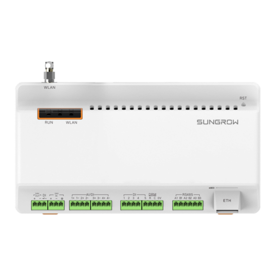
Page 20: Product Introduction
Refer to "table 5-1 Port description" Note: D* is 4G antenna mounting hole. The Logger1000A is provided with the hole while the Logger1000B is not. Specifically, refer to the actual product received. In the following, de- scription is given by using the Logger1000A as an example. - Page 21 (WLAN) Data communication in Slow flash process Note: * Only the Logger1000A is equipped with the 4G indicator. • Slow flash means that the indicator flashes once every second. • Slow flash of the communication indicator indicates data communication in process. If there has been no data communication with iSolarCloud for 10s, the indicator will keep steady on.
-
Page 22: Unpacking And Storage
2 sets, E/UK-1201442, fixed on the guide rail to Terminal fastener prevent the Logger1000 from moving Length: 240mm Guide rail The Logger1000A is provided with the 4G antenna WLAN antenna mounting hole while Logger1000B is not. Specifi- 4G antenna cally, refer to the actual product received. -
Page 23: Identifying The Logger1000
Ensure that the device type is correct. • Check the device thoroughly and ensure there are no visible damages. If there are any problems, contact SUNGROW or the forwarding company. Only undamaged Logger1000 can be installed and commissioned. Before installa- tion, ensure that: •... - Page 24 3 Unpacking and Storage User Manual • The storage environment should be well ventilated, dry, and without any accumulated water. • Ambient temperature: -40℃ to +70℃; relative humidity: 0~95%, no condensation. • Take precautions to protect the device against damage due to harsh environment such as shock cooling, shock heating, and collision.
-
Page 25: Mechanical Mounting
Mechanical Mounting Respect all local standards and requirements during mechanical installation. Installation Location Selection Selecting an optimal installation location for the Logger1000 is critical to safe operation, long service life, and sound performance. Take the following requirements into account when selecting the installation location: •... -
Page 26: Installation Tools
4 Mechanical Mounting User Manual Installation Tools Installation tools include but are not limited to the following recommended ones. If necessary, use other auxiliary tools on site. Installation Method The Logger1000 can be installed in the wall-mounting manner or guide rail-mounting man- ner, and users can select either one according to onsite condition. - Page 27 User Manual 4 Mechanical Mounting Step 2 Mark positions for drilling holes with a marker. Step 3 Drill the holes with a drill according to the marked positions. Avoid drilling holes in the utility pipes and/or cables attached to back of the wall! Operation personnel should wear goggles and dust mask throughout the drilling process to avoid dust inhalation or contact with eyes.
-
Page 28: Guide Rail-Mounted Installation
4 Mechanical Mounting User Manual Step 5 Fix the screw or bolt on the installation surface, where the screw protrudes from the wall sur- face by about 5mm.Hang the Logger1000 onto the screws on the concrete wall or metal sur- face via the wall-mounting holes on the back of Logger1000. - Page 29 User Manual 4 Mechanical Mounting Step 2 Slight press down the recessed part under the buckle of Logger1000 with a flat-head screw- driver or other similar tools to pull out the buckle outwards. Step 3 Hook the Logger1000 into the guide rail from above and press down the lower part of the Logger1000 until it snaps into place.
-
Page 30: Installing Antenna
4 Mechanical Mounting User Manual Step 6 Check and ensure that the Logger1000 is firmly installed. - - End Installing Antenna The sucker antenna base should be placed on a metal surface outside the container to avoid impact on signal reception. Antenna entry should be reserved on the container, and the entry hole size is 20mm. - Page 31 User Manual 4 Mechanical Mounting Step 2 Tilt the power box and hook the buckle into the guide rail. Press down the power box until it snaps into place with an audible "Click" sound. Step 3 The installation of the power box and Logger1000 is completed. - - End...
-
Page 32: Electrical Connection
Electrical Connection Safety Instructions Incorrect cable connection may cause device damage or even personal injury. All cables must be intact, well insulated, appropriately dimensioned, and firmly connected. Port Introduction External wiring terminals are located at the bottom of Logger1000, and the wiring area is shown in the figure below. -
Page 33: Connection To Pv Devices
4G antenna Restart Press it for 3s to restart Note: * Only the Logger1000A is equipped with the SIM card slot and the 4G function. For the RS485 (A1B1~A3B3) ports, the communication distance should not ex- ceed 1,000m. Connection to PV Devices Devices in the PV system that can be connected to the Logger1000 include the inverter, Me- teo Station, Smart Energy Meter, etc. - Page 34 5 Electrical Connection User Manual Step 2 Strip the cable jacket and insulation layer with a wire stripper by about 15mm and 8mm to 10mm respectively. Step 3 Connect the stripped cable to the RS485 ports of the Logger1000, as shown in the figure below.
-
Page 35: Rj45 Port Connection
User Manual 5 Electrical Connection 5.3.1.2 RJ45 port connection Communication cable specification: Cable Type RJ45 communication cable Shielded twisted pair Ethernet cable Step 1 Lead the RJ45 communication cable from the inverter to the wiring area of Logger1000. Step 2 Strip the insulation layer of the communication cable with an Ethernet wire stripper, and lead the corresponding RS485A/B signal cables out. -
Page 36: Connection To Multiple Devices
The addresses of devices on each RS485 bus must be different from one another and within the address range set for the Logger1000 (address range of residential inverters and string inverters manufactured by SUNGROW: 1-247; address range of third-party devices: 1-255). Otherwise, communication error will occur. - Page 37 Protocol Type Wiring Manufacture Sfere PD194E/Z Acrel PZ96-E3 Acrel DTSD1352 Modbus RTU " RS485 Connection" Weidmüller EM 610 SUNGROW DTSU666 Schneider IEM3255 " RS485 Connection" Modbus RTU UMG604, Janitza " Ethernet UMG104 Modbus TCP Connection" RS485 Connection The following figure shows the connection between the Logger1000 and the Smart Energy Meter.
-
Page 38: Connection To Meteo Station
5 Electrical Connection User Manual Prepare two appropriate Ethernet cables. Connect the cable led from the Smart Energy Me- ter to a port of the core switch. Connect one end of the other Ethernet cable to another port of the core switch and the other end to the "ETH" port of the Logger1000. If there is no core switch connected on site, connect the cable led from the Smart Energy Meter directly to the "ETH"... -
Page 39: Connection To Background
User Manual 5 Electrical Connection If multiple inverters are connected to the Logger1000 together with the Meteo Sta- tion, the Meteo Station should be connected on the very end of the daisy chain. AI Connection The following figure shows the connection between the Logger1000 and the Meteo Station. Connect the communication cable led from the Meteo Station to the AI port of the Logger1000. -
Page 40: Connection To Micro-Sim
5 Electrical Connection User Manual Step 3 Set IP address of the ETH port to be within the same network segment as that of the back- ground monitoring system. figure 5-2 Connection to PV background system Default IP of the "ETH" IP:12.12.12.12. - - End Connection to Micro-SIM Micro-SIM Card Requirements... -
Page 41: Connection To Power Box
User Manual 5 Electrical Connection • Insert a Micro-SIM card into the SIM card slot. The Micro-SIM card supports hot-plugging. Connection to Power Box The Logger1000 supports DC24V power supply. Prepare two-core DC cable, three-core AC cable, and grounding cable before wiring. Power cable specifications are shown in the table below. - Page 42 5 Electrical Connection User Manual Step 1 Strip the cable jackets and insulation layers of the DC cable, AC cable, and grounding cable with a wire stripper by appropriate length. Step 2 Insert the stripped DC cable into the "24V IN" and "24V OUT" ports of the Logger1000. Con- nect the DC cable led from the "24V OUT"...
-
Page 43: Cable Routing Requirements
User Manual 5 Electrical Connection Step 4 Connect the DC cable led from the "24V IN" port of the Logger1000 to the "DC 24V OUT" port of the power box. Connect the stripped AC cable to the "AC (100~277V)" port of the power box, and connect the other end of the AC cable to the 220V AC power. -
Page 44: Commissioning
Commissioning Inspection before Commissioning Inspection item Result All cables are intact, well-insulated, and appropriately □ dimensioned All cables are connected correctly and firmly □ The polarity of the power supply cable is correct. The □ grounding cable is reliably grounded Commissioning Steps Step Result... - Page 45 Create new plant via the iSolarCloud App and check the iSolar- □ Cloud data for correctness. The auto search function is available for SUNGROW string inverters whose ad- dresses are automatically allocated. Devices of other types, such as Smart Energy Meter and transformer, can be con- nected to Logger1000 via the adding device function.
- Page 46 6 Commissioning User Manual Use the iSolarCloud App to create a new plant. Users can directly scan the QR code on the front label of the Logger1000 or manually input the S/N to add com- munication equipment. For details, refer to the Quick Guidance of iSolarCloud App.
-
Page 47: Web Interface
WEB Interface Running Requirements Item Parameter IE11 or later, Chrome65 or later, and Safari11 or Browser later Min. resolution 1024*768 Login Steps The Web interfaces provided in this document are for reference only, and the ac- tual ones may differ. Users of different types have different permissions. -
Page 48: Ethernet Login
The account will be locked out if you have entered a wrong password for 6 times in a row. In this case, please wait 10 minutes and try logging in again. With the login password forgotten, contact SUNGROW and provide the device S/ N as well as system time, to get the password. -
Page 49: Web Main Interface
User Manual 7 WEB Interface hacked or compromised if you use the default password for a long time; and you may not be able to access the device if you have lost your password. These situations may cause losses for the plant, and such losses shall be borne by users. Step 1 Choose “O&M User→Modify Password”... -
Page 50: Web Menu
7 WEB Interface User Manual Designation Description Item Display the counts of Fault and Alarm of the con- Optimizer fault nected optimizer. Click the icon to enter the "7.7 Device and alarm Monitoring" interface. Display the current alarm level and alarm number. Alarm icon Users can click the icons to enter the corresponding alarm interface... -
Page 51: Operation Procedure
Refer to the chapter "7.10.5 System Time". Step 4 Automatically search the device. Devices that can be automatically searched, such as SUNGROW string inverter, can be added via the auto search function with addresses allocated automatically. Refer to the chapter "7.8.1 Device List". -
Page 52: Overview
7 WEB Interface User Manual Step 6 Configure forwarding service. After all devices have been added, configure the forwarding service of the Logger1000, to ensure that the Logger1000 can forward the data to upstream devices. Refer to the chapter "7.10.6 iSolarCloud"~"7.10.9 Third-party portal". -
Page 53: Device Monitoring
Please contact SUNGROW if you want to check the data uploaded after the network out- age event. -
Page 54: Single Setting
7 WEB Interface User Manual 7.7.3.1 Single setting Step 1 Select the desired Country/Region and Grid type. Step 2 Click Settings to set initial parameters for the single device. - - End 7.7.3.2 Batch setting Step 1 Select the desired Country/Region and Grid type. Step 2 Click Configure Synchronization. -
Page 55: Power Regulation Parameters
User Manual 7 WEB Interface 7.7.8 Power Regulation Parameters Click “Power Monitoring→Power Regulation Parameters”, and set power regulation pa- rameters on the corresponding interface. Two methods are available for power regulation parameter setting: Single Setting and Batch Settings. Please refer to "7.7.3 Initial Parameter"... -
Page 56: Device Information
Devices can be automatically searched and added. 7.8.1.1 Auto search The Auto Search function is used for SUNGROW string inverter to which addresses will be automatically allocated. Step 1 Click “Device→Device List” to enter the corresponding interface. -
Page 57: Add Device
User Manual 7 WEB Interface Step 2 Click the button to export the device list. Step 3 After the device list is exported, the user can modify device names in batch. Step 4 After the modification is completed, save the device list file in the .csv format. Step 5 Click the button to import the .csv file into the Web. - Page 58 7 WEB Interface User Manual Step 5 Select Custom option in the Configuration Method. Click Next to enter Configure Measur- ing Point the interface. table 7-1 Parameter description Description Parameter Refer to the communication protocol of the meter, parse Byte Order the order of the read byte stream Refer to the communication protocol of the meter, voltage PT Transformation Ratio...
-
Page 59: Add The Third-Party Meteo Staion (Import Files)
User Manual 7 WEB Interface Step 8 Enter the template name in the pop-up prompt window and click Confirm on the prompt win- dow to save the template. The template name should be a combination of numbers, letters, dashes and underscores starting with English letters, with a maximum length of 32 bits. -
Page 60: Edit Device
7 WEB Interface User Manual Step 5 Select Custom option in the Configuration Method. Click Next to enter Configure Measur- ing Point the interface. table 7-2 Parameter description Description Parameter Refer to the device Modbus map, parse the order of the Byte Order read byte stream Beginning Address... -
Page 61: Delete Device
Step 3 Click Confirm in the pop-up window, to delete the device. - - End 7.8.2 Firmware Update The Firmware Update function is used to upgrade the SUNGROW residential inverter and string inverter. Step 1 Click “Device→Firmware Update” to enter the corresponding interface. -
Page 62: Inverter Log
Step 3 Find the .txt file, which is contained in the exported file mentioned in Step 2, and open it using iConfig. You may now check the fault recording of the device. Please contact SUNGROW customer service for the installation package of and instructions for iConfig. -
Page 63: System
User Manual 7 WEB Interface 7.10 System 7.10.1 Run Information Click “System→Run Information” to enter the corresponding interface. General Information Check information like system time, IP address, MAC address, and mobile network. IO Information Check information like AI voltage and current values, and DI status. Forwarding Information Check the current value of MODBUS-TCP and IEC104 parameters. -
Page 64: Remote Maintenance
7 WEB Interface User Manual Step 3 A warning window will pop up, and click Confirm to continue the reset all settings operation. - - End Restoring the factory settings refers to restoring all modified settings to the factory state and will not clear the data. 7.10.3 Remote Maintenance Step 1 Click “System→Remote Maintenance”... -
Page 65: Message Export
User Manual 7 WEB Interface 7.10.4 Message Export Step 1 Click “System→Message Export” to enter the corresponding interface. table 7-4 Parameter description Description Range Parameter Serial port: COM1、COM2、COM3 Port Network port: ETH, WiFi, Mobile Network Export the message re- Duration 1min ~ 10min corded during the set time Step 2 Set parameters, including Port, Serial Port, and Duration, and click Start to start recording... -
Page 66: Isolarcloud
User Manual Method of setting system time: • When the option Inverter Timing is selected, SUNGROW inverter time will be synchron- ized with the time of Logger1000. • When the clock source is set to User Define, user can manually set the current system time and time zone in the following two manners: –... -
Page 67: Iec104
User Manual 7 WEB Interface - - End The default iSolarCloud station is Chinese Server. Users in mainland China se- lect Chinese Server, users in Europe select European Server,users in Australia select Australian Server,and users in other regions select the International Server. -
Page 68: Edit Iec104 Forwarding Point Table
7 WEB Interface User Manual 7.10.7.3 Edit IEC104 Forwarding Point Table Step 1 Click Export of Configuration Tools to export the IEC104 forwarding point table. Step 2 Open the sheet Introduce of the IEC104 forwarding point table, where data of five types (telemetry, telesignalling, remote pulse, remote control, and remote regulating) are included. - Page 69 User Manual 7 WEB Interface Step 4 Open the sheets such as inverter, Smart Energy Meter, Meteo Station, and Logger1000, to set corresponding measuring point data. table 7-7 Parameters of each equipment tab Data Coeffi- Data DataID State Invert Unit Type cient Name...
-
Page 70: Import Iec104 Forwarding Point Table
7 WEB Interface User Manual Step 5 Open the sheet Device List of the IEC104 forwarding point table to sort the devices. figure 7-1 Device List tab parameters table 7-9 Description of parameter Description Parameter Sort devices, and only support moving the whole line for the de- vice type corresponds one-to-one to its parameters in the same line Device Type... -
Page 71: Modbus
User Manual 7 WEB Interface Step 2 After editing the IEC104 forwarding point table, click “Export→IEC104 CFG” in the menu bar, and the prompt window will pop up. Convert the excel file into .xml file, where the .xml file and the excel file are in the same path. Step 3 Click Add, to enter the Advanced Settings interface. -
Page 72: Third-Party Portal
Step 4 Modify the configuration information and click Save. Set the FTP path and name it as "/FTP server directory". For example, for the name "/SUNGROW", / is the root directory, and SUNGROW is the directory where data is stored on the FTP server. -
Page 73: Rs485
User Manual 7 WEB Interface 7.10.11.1 RS485 Step 1 Click “System→Port Parameter→RS485” to enter the corresponding interface. Step 2 Click to modify Baud Rate, Parity Bit, and Stop Bit. Step 3 Click Save to save the information. - - End When the Logger1000 is connected to a device via the serial port, the Baud Rate, Parity Bit, and Stop Bit of the serial port should be the same as those set for the connected device, so as to ensure normal communication between the Log-... -
Page 74: Ethernet
7 WEB Interface User Manual If there are slave nodes that have not been successfully networked, users will be prompted with the slave node information (S/N and Device Address) after click- ing Configure Synchronization. Click Export to save the information to local. Parameters such as frequency of slave nodes that have not been successfully networked can be set on near-end devices. -
Page 75: Mobile Network
User Manual 7 WEB Interface Step 2 If auto IP allocation is , it is recommended to obtain the current IP address of the ETH port by connecting the WLAN module and logging into 11.11.11.1. Step 3 If the parameter Automatically obtain IP settings (DHCP) is set to fill in the informa- tion such as the IP Address, Subnet Mask, and Default Gateway, and click the button to save the operation. - Page 76 7 WEB Interface User Manual table 7-13 Description of hotspot parameter Description Parameter Enable: Turn on the Logger1000 hotspot. Users can then search for the hotspot on a PC or mobile phone. AP hotspot enable switch Disable: Turn off the Logger1000 hotspot. Then, users can- not log into the Web system by connecting to the hotspot.
- Page 77 User Manual 7 WEB Interface Step 2 Set the following parameters. Description Parameter The status of the DI port during normal operation. Initial Status The inverter status can be restored to normal by the following methods. Inverter Action • Manual control: The user manually restore the inverter status to Triggered by DI normal.
- Page 78 7 WEB Interface User Manual Step 3 Click to save the settings. - - End 7.10.11.8 DO An external IO module is required to enable the DO function. Step 1 Choose “System→Port Parameter→DO”, and enter the corresponding interface. Step 2 Set the following parameters. Description Parameter The status of the DO port during normal operation.
-
Page 79: Mplc
User Manual 7 WEB Interface 7.10.12 MPLC Step 1 Click “System→MPLC”, select the MPLC to be set, and click on the right to enter the corresponding interface and set the following parameters: Band Num: Band1, default band. Band2, standby band. Array ID: Select the current array ID. -
Page 80: Grid Dispatching Function
Multiple regulation manners can meet different regulation requirements. The Logger1000 can regulate the power output of the SUNGROW inverter, and the regulation mainly includes active power control and reactive power regulation. The Logger1000 can control device power output according to the local preset instructions. -
Page 81: Interface Description
User Manual 8 Grid Dispatching Function The corresponding power dispatching function is available only when the inverter supports active power control, power factor control, and reactive power regulation! For details, refer to the inverter user manual or consult the local retailer. Interface Description The Logger1000 is equipped with digital control interfaces and analog control interfaces for receiving digital instructions and analog instructions sent by the grid dispatching center. -
Page 82: Analog Control Interface
8 Grid Dispatching Function User Manual In Germany and some other European countries, the grid company uses the Ripple Control Receiver to convert the grid dispatching signal and send it in a dry contact manner, In this case, the plant needs to receive the grid dispatching signal in the dry contact communication manner. -
Page 83: Drm Control Interface
User Manual 8 Grid Dispatching Function table 8-2 Analog control interface signal definition Signal Definition 1+,1-,2+,2-,3+,3-,4+,4- 4 analog input channels The Logger1000 supports 4 inputs of 4~20mA analog currents or 4 inputs of 0~10V analog voltage. 8.2.3 DRM Control Interface The DRM control interface are located at the bottom of the Logger1000, as shown in the fig- ure below. -
Page 84: Remote Power Control
8 Grid Dispatching Function User Manual Step 2 Set the active control mode to Disable Derating and click Save. - - End 8.3.1.2 Remote power control When the instruction source is IEC104 or MODBUS TCP protocol, set the active control mode to Remote power control. - Page 85 User Manual 8 Grid Dispatching Function Step 3 Set remote dispatching parameters. For specific parameter description, refer to the following table. table 8-3 Parameter description Description Parameter Open-loop control: Remote monitoring background is con- nected and active instruction of remote dispatching is sent to the power output port of the inverter, thereby achieving active power control.
-
Page 86: Local Power Control
8 Grid Dispatching Function User Manual Description Parameter If the adjustment does not reach the set target value, in- Adjustment ratio (%)* crease or decrease adjustment value according to the set adjustment ratio, so as to reach the target value. Time interval of delivering dispatching instructions Control Cycle (5-60)S Parameter range: 5~60s... - Page 87 User Manual 8 Grid Dispatching Function Step 3 Set local dispatching parameters. For specific parameter description, refer to the following table. table 8-4 Parameter description Description Parameter Open-loop control:At the start time, the locally config- ured active instruction is sent to the power output port of the inverter, thereby implementing active power control.
- Page 88 8 Grid Dispatching Function User Manual Description Parameter Enable: when feed-in power is detected, the Log- ger1000 will deliver stop instruction to the inverter. Disable: when feed-in power is detected, the Log- Feed-in stop * ger1000 will not deliver stop instruction to the inverter. Note: Never turn on the Enable switch arbitrarily! Gener- ally, keep it in Disable state.
-
Page 89: Analog Input
User Manual 8 Grid Dispatching Function 8.3.1.4 Analog Input When using the analog signal at the AI port of the Logger1000 as the dispatching input, set the active control mode to Analog input. Step 1 Click “Power control→Active power” to enter the active power interface. Step 2 Set the active control mode to Analog input. - Page 90 8 Grid Dispatching Function User Manual Step 3 Set AI control parameters. For specific parameter description, refer to the following table. table 8-5 Parameter description Description Parameter Open-loop control: Active instruction controlled by AI is sent to the power output port of the inverter, thereby achieving ac- tive power control.
-
Page 91: Digital Input
User Manual 8 Grid Dispatching Function Description Parameter Sampling Value Less Time taken for the DO port to restore to the initial state in the Than Lower Limit Fault event of the sampling value from the AI channel falling below Recovery Time (s) the lower limit. - Page 92 8 Grid Dispatching Function User Manual Step 3 Set DI control parameters. For specific parameter description, refer to the following table. table 8-6 Parameter description Description Parameter Open-loop control: Active instruction controlled by DI is sent to the power output port of the inverter, thereby achieving active power control.
-
Page 93: Drm Mode
User Manual 8 Grid Dispatching Function 8.3.1.6 DRM mode When using the digital signal at the DI port (DI1 ~ DI4) of the Logger1000 as the dispatching input, set the active control mode to DRM mode. Step 1 Click “Power control→Active power” to enter the active power interface. Step 2 Set the active control mode to DRM mode and click Save. - Page 94 8 Grid Dispatching Function User Manual Step 1 Click “Power control→Reactive power” to enter the reactive power interface. Step 2 Set the Reactive Control Mode to Remote power control.
- Page 95 User Manual 8 Grid Dispatching Function Step 3 Set remote dispatching parameters. For specific parameter description, refer to the following table. table 8-7 Parameter description Description Parameter Open-loop control: Remote monitoring background is con- nected and active instruction of remote dispatching is sent to the power output port of the inverter, thereby achieving active power control.
-
Page 96: Local Power Control
8 Grid Dispatching Function User Manual Description Parameter Forward Direction: The reactive power direction of the in- verter array displayed by the meter/transformer is the same as the actual reactive power direction. Reactive power direction* Direction Reverse: The reactive power direction of the in- verter array displayed by the meter/transformer is opposite to the actual reactive power direction. - Page 97 Note: *Only when the control method is set to Closed-loop control, the parameter Select energy meter / transformer is settable. When selecting an energy meter, the Logger used must be the one manufactured by SUNGROW. Step 4 Add local power control manner Fill in Start time and Percentage(PF), and click Save.
-
Page 98: Analog Input
8 Grid Dispatching Function User Manual 8.3.2.4 Analog Input When using the analog signal at the AI port of the Logger1000 as the dispatching input, set the Reactive Control Mode to Analog input. Step 1 Click “Power control→Reactive power” to enter the reactive power interface. Step 2 Set the reactive control mode to Analog input. -
Page 99: Digital Input
User Manual 8 Grid Dispatching Function Step 4 After finishing parameter setting, click Save to save the operation. - - End 8.3.2.5 Digital Input When using the digital signal at the DI port of the Logger1000 as the dispatching input, set the Reactive Control Mode to Digital input. -
Page 100: Country Mode
8 Grid Dispatching Function User Manual Delete digital input manner: select a digital input manner that needs to be deleted, and click Clear data. 8.3.2.6 Country Mode If the dispatching input must be the national power dispatching instruction, the Reactive Control Mode is set to Country mode. -
Page 101: Device Maintenance
Device Maintenance Due to the effect of ambient temperature, humidity, dust and vibration, the inner components of the Logger1000 will be aging and worn out. To ensure the system safety and maintain the efficiency of the Logger1000, it is necessary to carry out routine and periodic maintenance. All measures, which can help the Logger1000 to keep good working conditions, are within the maintenance scope. -
Page 102: Troubleshooting
The grounding cable must be grounded reliably. Otherwise, electric shock can cause personal injury! The common faults and troubleshooting is shown in the table below. If the problem still can- not be removed by following the instruction in this manual, please contact SUNGROW. - Page 103 Power-on fault 2. Power source failure 2. Replace the power source 3. Logger1000 fault 3. Contact SUNGROW 1. The RS485 port is not con- 1. Check the RS485 communica- nected to any devices or the con- tion cable connection; reconnect nection cable is loose or and tighten the cable if necessary.
- Page 104 9 Device Maintenance User Manual Fault Cause Corrective measures 1. Check the cable connection between the device and Log- ger1000; and reconnect and 1. Communication cable between tighten the cable if necessary. the device and the Logger1000 is 2. Power on the device if the de- The Logger1000 loose or disconnected.
-
Page 105: Appendix
10 Appendix 10.1 Technical Data Communication Max. number of devices 30 at most* Communication ports RS485 interface 1 x RJ45, 10/100/1000Mbps Ethernet Digital input 5, Max. 24VDC Analog input 4, support 4~20mA or 0~10VDC Wireless Communication LTE(FDD): B1, B3, B5, B8 LTE(TDD): B38,B39, B40, B41 TD-SCDMA: B34, B39 4G Communication... -
Page 106: Dry Contact Wiring Cable
• The customer shall give SUNGROW a reasonable period to repair the faulty device. Exclusion of Liability In the following circumstances, SUNGROW has the right to refuse to honor the quality guarantee: • The free warranty period for the whole machine/components has expired. -
Page 107: Contact Information
The fault or damage is caused by installation, repairs, modification, or disassembly per- formed by a service provider or personnel not from SUNGROW. • The fault or damage is caused by the use of non-standard or non-SUNGROW compo- nents or software. •... - Page 108 Sungrow Power Supply Co., Ltd. www.sungrowpower.com...
Need help?
Do you have a question about the Logger1000A and is the answer not in the manual?
Questions and answers