Sungrow Logger1000A User Manual
Hide thumbs
Also See for Logger1000A:
- User manual (108 pages) ,
- Quick installation manual (30 pages) ,
- User manual (94 pages)
Table of Contents
Advertisement
Quick Links
L L o o g g g g e e r r 1 1 0 0 0 0 0 0 A A / / L L o o g g g g e e r r 1 1 0 0 0 0 0 0 B B D D a a t t a a
L L o o g g g g e e r r U U s s e e r r
M M a a n n u u a a l l L L o o g g g g e e r r 1 1 0 0 0 0 0 0 A A _ _ B B - - U U E E N N - -
V V e e r r 1 1 5 5 - - 2 2 0 0 2 2 1 1 0 0 7 7 V V e e r r s s i i o o n n : : 1 1 . . 5 5
Logger1000A_B-UEN-Ver15-202107 Version:1.5
Logger1000A/Logger1000B
D D a a t t a a L L o o g g g g e e r r
U U s s e e r r M M a a n n u u a a l l
Advertisement
Table of Contents

Related Manuals for Sungrow Logger1000A


Summary of Contents for Sungrow Logger1000A
- Page 1 V V e e r r 1 1 5 5 - - 2 2 0 0 2 2 1 1 0 0 7 7 V V e e r r s s i i o o n n : : 1 1 . . 5 5 Logger1000A_B-UEN-Ver15-202107 Version:1.5 Logger1000A/Logger1000B D D a a t t a a L L o o g g g g e e r r...
-
Page 3: Table Of Contents
C C o o n n t t e e n n t t s s 1 About this Manual ..................1 1.1 Intended Use....................1 1.2 Target Group....................1 1.3 How to Use This Manual................1 1.4 Symbol Explanations ..................2 2 Safety Instruction .................. - Page 4 7.3.1 Connection to a single inverter ............21 7.3.2 Connection to multiple devices ............24 7.3.3 Connection to Smart Energy Meter ........... 24 7.3.4 Connection to Meteo Station............. 26 7.4 Connection to Background ................. 27 7.5 Connection to Micro-SIM................28 7.6 Connection to Power Box ................
- Page 5 9.10 System ....................48 9.10.1 Running Information ............... 48 9.10.2 System Maintenance ..............48 9.10.3 Remote Maintenance ..............49 9.10.4 Message Export ................50 9.10.5 System Time................... 51 9.10.6 iSolarCloud..................52 9.10.7 IEC104 ................... 53 9.10.8 MODBUS..................56 9.10.9 Third-party portal ................57 9.10.10 Port Parameter ................
-
Page 7: About This Manual
Any reproduction or disclosure, even partially, of the contents of this manual is strictly prohibited without prior written authorization of SUNGROW. The content of the manual will be periodically updated or revised as per the product development. It is probably that there are changes in manuals for the subsequent module edition. -
Page 8: Symbol Explanations
1 About this Manual User Manual 1.4 Symbol Explanations This manual contains important safety and operational instructions that must be accurately understood and respected during the installation and maintenance of the equipment. To ensure the optimum use of this manual, note the following explanations of the symbols used. -
Page 9: Safety Instruction
B B e e f f o o r r e e I I n n s s t t a a l l l l a a t t i i o o n n After receiving the device, please check if there is damage caused during transport. Contact SUNGROW or the forwarding company once any problem is detected. - Page 10 User can never maintain or replace the modules and other parts. Serious personal injury or property loss may follow if otherwise. Never replace the internal components of the Logger1000 without authorization. SUNGROW shall not be held liable for any possible damage caused by ignorance of this warning.
-
Page 11: Product Introduction
Product Introduction 3.1 Function Description 3.1.1 Brief Product Introduction The Logger1000 is a device used for data collection, power control, and protocol conversion for inverters and other PV equipment in the PV plant. The device is also integrated with communication gateway and plant O&M function. The Logger1000 is featured as flexible networking, auxiliary maintenance, and easy operation. - Page 12 3 Product Introduction User Manual The Logger1000 can be connected to iSolarCloud via the router or connected to the iSolarCloud via the WiFi or 4G network.
-
Page 13: Appearance
Refer to "Table 7-1 Port description" Note: D* is 4G antenna mounting hole. The Logger1000A is provided with the hole while the Logger1000B is not. Specifically, refer to the actual product received. In the following, description is given by using the Logger1000A as an example. -
Page 14: Dimensions
(WLAN) Data communication in Slow flash process Note: * Only the Logger1000A is equipped with the 4G indicator. Slow flash means that the indicator flashes once every second. • Slow flash of the communication indicator indicates data communication in process. -
Page 15: Installation Flow
Installation Flow The following figure shows the overall installation flow of Logger1000. F F i i g g u u r r e e 4 4 - - 1 1 Installation Flow Table 4-1 Description of the installation flow N N o o . . P P r r o o c c e e d d u u r r e e R R e e f f e e r r e e n n c c e e c c h h a a p p t t e e r r "5.1 Scope of Delivery"... -
Page 16: Unpacking And Storage
Unpacking and Storage 5.1 Scope of Delivery Check the scope of delivery for completeness according to the packing list. The following items should be included. F F i i g g u u r r e e 5 5 - - 1 1 Scope of delivery D D e e s s i i g g n n a a t t i i o o n n D D e e s s c c r r i i p p t t i i o o n n I I t t e e m m... -
Page 17: Identifying The Logger1000
• Check the device thoroughly and ensure there are no visible damages. • If there are any problems, contact SUNGROW or the forwarding company. Only undamaged Logger1000 can be installed and commissioned. Before installation, ensure that: The Logger1000 is intact without any damages. -
Page 18: Storage
5 Unpacking and Storage User Manual 5.4 Storage If the Logger1000 is not to be installed immediately after receiving, observe the following requirements to store it properly: The Logger1000 should be store in its original packing case and placed in a •... -
Page 19: Mechanical Installation
Mechanical Installation 6.1 Installation Location Selection Selecting an optimal installation location for the Logger1000 is critical to safe operation, long service life, and sound performance. Take the following requirements into account when selecting the installation location: With the ingress of protection IP 20, the Logger1000 can be installed only indoors. •... -
Page 20: Installation Tools
6 Mechanical Installation User Manual 6.2 Installation Tools Installation tools include but are not limited to the following recommended ones. If necessary, use other auxiliary tools on site. 6.3 Installing Logger1000 The Logger1000 can be installed in the wall-mounting manner or guide rail-mounting manner, and users can select either one according to onsite condition. - Page 21 User Manual 6 Mechanical Installation Step 2 Mark positions for drilling holes with a marker. Step 3 Drill the holes with a drill according to the marked positions. Avoid drilling holes in the utility pipes and/or cables attached to back of the wall! Operation personnel should wear goggles and dust mask throughout the drilling process to avoid dust inhalation or contact with eyes.
-
Page 22: Guide Rail-Mounted Installation
6 Mechanical Installation User Manual Step 6 Check and ensure that the Logger1000 is firmly installed. - - - - E E n n d d 6.3.2 Guide Rail-Mounted Installation Secure the Logger1000 via the rail buckles (as shown in the figure below) on the back of it. -
Page 23: Installing Antenna
User Manual 6 Mechanical Installation Step 3 Hook the Logger1000 into the guide rail from above and press down the lower part of the Logger1000 until it snaps into place. Step 4 Push the buckle of the Logger1000 upwards to clamp the guide rail. Step 5 Secure the terminal fasteners on both ends of the guide rail, to prevent the Logger1000 from moving. -
Page 24: Installing Power Box
6 Mechanical Installation User Manual 6.5 Installing Power Box Mount the power box onto the concrete wall or metal surface according to onsite conditions. Secure the power box via the buckles (as shown in the figure below) on the back of it. Step 1 Install and secure the power box guide rail at the appropriate location. - Page 25 User Manual 6 Mechanical Installation Step 3 The installation of the power box and Logger1000 is completed. - - - - E E n n d d...
-
Page 26: Electrical Connection
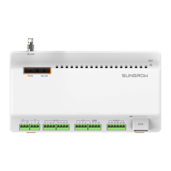
Electrical Connection 7.1 Safety Instructions Incorrect cable connection may cause device damage or even personal injury. All cables must be intact, well insulated, appropriately dimensioned, and firmly connected. 7.2 Port Introduction External wiring terminals are located at the bottom of Logger1000, and the wiring area is shown in the figure below. -
Page 27: Connection To Pv Devices
WLAN antenna 4G antenna Restart Press it for 3s to restart Note: * Only the Logger1000A is equipped with the SIM card slot and the 4G function. For the RS485 (A ) ports, the communication distance should not exceed 1,000m. - Page 28 7 Electrical Connection User Manual Step 3 Connect the stripped cable to the RS485 ports of the Logger1000, as shown in the figure below. RS485A is connected to port A while RS485B is connected to port B. The RS485 communication cable must be the shielded twisted pair with the shielding layer single-point grounded.
- Page 29 User Manual 7 Electrical Connection 7.3.1.2 RJ45 port connection C C o o m m m m u u n n i i c c a a t t i i o o n n c c a a b b l l e e s s p p e e c c i i f f i i c c a a t t i i o o n n : : C C a a b b l l e e T T y y p p e e RS485 communication cable...
-
Page 30: Connection To Multiple Devices
• and within the address range set for the Logger1000 (address range of residential inverters and string inverters manufactured by SUNGROW: 1-247; address range of third-party devices: 1-255). Otherwise, communication error will occur. Serial port parameters of each device on the RS485 bus should be consistent with •... - Page 31 M M a a n n u u f f a a c c t t u u r r e e Sfere PD194E/Z Acrel PZ96-E3 " RS485 Acrel DTSD1352 Modbus RTU Connection" Weidmüller EM 610 SUNGROW DTSU666 Schneider IEM3255 " RS485 Modbus RTU Connection" UMG604, Janitza UMG104 Modbus TCP " Ethernet Connection"...
-
Page 32: Connection To Meteo Station
7 Electrical Connection User Manual Step 1 Prepare two appropriate Ethernet cables. Step 2 Connect the cable led from the Smart Energy Meter to a port of the core switch. Step 3 Connect one end of the other Ethernet cable to another port of the core switch and the other end to the "ETH"... -
Page 33: Connection To Background
User Manual 7 Electrical Connection R R S S 4 4 8 8 5 5 C C o o n n n n e e c c t t i i o o n n The following figure shows the connection between the Logger1000 and the Meteo Station. -
Page 34: Connection To Micro-Sim
7 Electrical Connection User Manual Step 2 Insert one end of the cable into the port of the Ethernet switch and the other end to the "ETH" port of the Logger1000. Step 3 Set IP address of the ETH port to be within the same network segment as that of the background monitoring system. - Page 35 User Manual 7 Electrical Connection Table 7-2 Power cable specification L L e e n n g g t t h h o o f f c c a a b b l l e e L L e e n n g g t t h h o o f f R R e e c c o o m m m m e e n n d d e e d d j j a a c c k k e e t t t t o o b b e e i i n n s s u u l l a a t t i i o o n n t t o o b b e e...
-
Page 36: Cable Routing Requirements
7 Electrical Connection User Manual Step 4 Connect the DC cable led from the "24V IN" port of the Logger1000 to the "DC 24V OUT" port of the power box. Connect the stripped AC cable to the "AC (100~277V)" port of the power box, and connect the other end of the AC cable to the 220V AC power. - Page 37 User Manual 7 Electrical Connection P P a a r r a a l l l l e e l l c c a a b b l l e e l l e e n n g g t t h h ( ( m m ) ) M M i i n n .
-
Page 38: Commissioning
Commissioning 8.1 Inspection before Commissioning I I n n s s p p e e c c t t i i o o n n i i t t e e m m N N o o . . R R e e s s u u l l t t All cables are intact, well-insulated, and appropriately □... - Page 39 Create new plant via the iSolarCloud App and check the □ iSolarCloud data for correctness. The auto search function is available for SUNGROW string inverters whose addresses are automatically allocated. Devices of other types, such as Smart Energy Meter and transformer, can be connected to Logger1000 via the adding device function.
- Page 40 8 Commissioning User Manual Use the iSolarCloud App to create a new plant. Users can directly scan the QR code on the front label of the Logger1000 or manually input the S/N to add communication equipment. For details, refer to the Quick Guidance of iSolarCloud App.
-
Page 41: Web Interface
Web Interface 9.1 Running Requirements I I t t e e m m P P a a r r a a m m e e t t e e r r Browser IE11 or later, Chrome65 or later, and Safari11 or later Min. -
Page 42: Ethernet Login
After login for the first time, it is recommended to change the password as soon as possible. Click "O&M user" -> "Modify password" to change the password. With the login password forgotten, contact SUNGROW and provide the device S/N as well as system time, to get the password. 9.2.2 Ethernet Login Step 1 The IP address of the PC connected to the Logger1000 is the same as that of the Logger1000. -
Page 43: Web Menu
User Manual 9 Web Interface D D e e s s i i g g n n a a t t i i o o n n D D e e s s c c r r i i p p t t i i o o n n I I t t e e m m Navigation menu Display main function modules of the Web... -
Page 44: Operation Procedure
"9.10.5 System Time". Step 4 Automatically search the device. Devices that can be automatically searched, such as SUNGROW string inverter, can be added via the auto search function with addresses allocated automatically. Refer to the chapter "9.8.1 Device List". -
Page 45: Overview
User Manual 9 Web Interface After all devices have been added, configure the forwarding service of the Logger1000, to ensure that the Logger1000 can forward the data to upstream devices. Refer to the chapter "9.10.6 iSolarCloud"~"9.10.9 Third-party portal". - - - - E E n n d d 9.6 Overview 9.6.1 General Information Click "Overview"... -
Page 46: Device Monitoring
9 Web Interface User Manual 9.7 Device Monitoring Click "Device Monitoring" to enter the corresponding interface. Device information such as real-time values, DC data, initial parameter, protection parameter, general parameter, device instruction and device information can be viewed on this interface. 9.7.1 RealTime Values Realtime information such as power generation, device state, and active power can be viewed on this interface. -
Page 47: Protection Parameter
User Manual 9 Web Interface 9.7.3.2 Batch setting Step 1 Select the desired country (region) and grid type. Step 2 Click "Configure Synchronization". Step 3 Select the desired devices in the pop-up device list, and click "Save" to achieve batch setting. -
Page 48: Device Information
Logger1000 and configuring addresses for these devices. Devices can be automatically searched and added. 9.8.1.1 Auto search The "Auto Search" function is used for SUNGROW string inverter to which addresses will be automatically allocated. Step 1 Click "Device" -> "Device List" to enter the corresponding interface. - Page 49 User Manual 9 Web Interface - - - - E E n n d d 9.8.1.3 Import Step 1 Click "Device" -> "Device List" to enter the corresponding interface. Step 2 Click the button “ ” to export the device list. Step 3 After the device list is exported, the user can modify device names in batch.
- Page 50 9 Web Interface User Manual Step 3 Select the port (COM1/COM2/COM3/NET) that the meter is actually connected to in the “Port”. Step 4 Select “Others” option in the “Device Model”. Step 5 Select “Custom” option in the “Configuration Method”. Click “Next” to enter “Configure Measuring Point”...
- Page 51 User Manual 9 Web Interface Only when the “Read-back Value” is consistent with the displayed value of the electric meter, the parameter setting of the measuring point is correct. Step 7 When the “Read-back Value” is consistent with the displayed value of the electric meter, click “Save Template”...
- Page 52 9 Web Interface User Manual Step 5 Select “Custom” option in the “Configuration Method”. Click “Next” to enter “Configure Measuring Point” the interface. Table 9-2 Parameter description D D e e s s c c r r i i p p t t i i o o n n P P a a r r a a m m e e t t e e r r Refer to the device Modbus map, parse the order of Byte Order...
-
Page 53: Firmware Update
- - - - E E n n d d 9.8.2 Firmware Update The firmware update function is used to upgrade the SUNGROW residential inverter and string inverter. Step 1 Click "Device" -> "Firmware Update" to enter the corresponding interface. -
Page 54: Afci Activation
9 Web Interface User Manual - - - - E E n n d d 9.8.4 AFCI Activation Step 1 Click "Device" -> "AFCI Activation" to enter the corresponding interface. Step 2 Check the devices that need to self-checking, click “Self-checking”and then "- Confirm"... -
Page 55: Remote Maintenance
User Manual 9 Web Interface 9.10.2.2 Log export Step 1 Click "System" -> "System Maintenance" to enter the corresponding interface. Step 2 Click the button "Log Export" to enter the corresponding interface. Step 3 Select the type of logs to be exported, and click "Confirm". - - - - E E n n d d 9.10.2.3 Rebooting Step 1 Click "System"... -
Page 56: Message Export
9 Web Interface User Manual Table 9-3 Parameter description R R e e m m o o t t e e m m a a i i n n t t e e n n a a n n c c e e s s w w i i t t c c h h D D e e s s c c r r i i p p t t i i o o n n s s t t a a t t e e Not allow for remote maintenance on the... -
Page 57: System Time
"Inverter Timing". Click "System" -> "System Time" to enter the corresponding interface. Method of setting system time: When the option "Inverter Timing" is selected, SUNGROW inverter time will be • synchronized with the time of Logger1000. -
Page 58: Isolarcloud
9 Web Interface User Manual When the clock source is set to "NTP", time of all devices can be synchronized. Click • the "Time Zone" pull-down-list and select the local time zone. Fill in the domain, set the time interval, and click "Save". In this way, the time of the Logger1000 is synchronized with the time of the server. -
Page 59: Iec104
User Manual 9 Web Interface 9.10.7 IEC104 Configure the IEC104 forwarding service for the Logger1000 on this interface. Server Mode • In the server mode, Logger1000 is used as a Server and connected to PC server to implement data transmission and instruction delivery. Click "System"... - Page 60 9 Web Interface User Manual Table 9-5 Introduce tab parameters D D a a t t a a T T y y p p e e D D e e s s c c r r i i p p t t i i o o n n Telemetry Telesignalling Remote pulse...
- Page 61 User Manual 9 Web Interface D D e e s s c c r r i i p p t t i i o o n n P P a a r r a a m m e e t t e e r r V V a a l l u u e e Coefficient, available for telemetry, remote Coefficient*...
-
Page 62: Modbus
9 Web Interface User Manual 9.10.7.4 Import IEC104 forwarding point table Step 1 After editing the IEC104 forwarding point table, click "Export" -> "IEC104 CFG", so that a prompt window pops up, and then convert the excel file into xml file. The xml file and the excel file are at the same path. -
Page 63: Third-Party Portal
Step 4 Modify the configuration information and click "Save". Set the FTP path and name it as "/FTP server directory". For example, for the name "/SUNGROW", / is the root directory, and SUNGROW is the directory where data is stored on the FTP server. - Page 64 9 Web Interface User Manual When the Logger1000 is connected to a device via the serial port, the baud rate, parity bit, and stop bit of the serial port should be the same as those set for the connected device, so as to ensure normal communication between the Logger1000 and the connected device.
-
Page 65: About
User Manual 9 Web Interface W W i i F F i i h h o o t t s s p p o o t t WiFi hotspot mode means that the Logger1000 is used as an hotspot, and the PC or mobile phone can be connected to the Logger1000 via the WiFi function. -
Page 66: Grid Dispatching Function
Multiple regulation manners can meet different regulation requirements. The Logger1000 can regulate the power output of the SUNGROW inverter, and the regulation mainly includes active power control and reactive power regulation. The Logger1000 can control device power output according to the local preset instructions. -
Page 67: Interface Description
User Manual 10 Grid Dispatching Function The corresponding power dispatching function is available only when the inverter supports active power control, power factor control, and reactive power regulation! For details, refer to the inverter user manual or consult the local retailer. 10.2 Interface Description The Logger1000 is equipped with digital control interfaces and analog control interfaces for receiving digital instructions and analog instructions sent by the grid dispatching... -
Page 68: Analog Control Interface
10 Grid Dispatching Function User Manual In Germany and some other European countries, the grid company uses the Ripple Control Receiver to convert the grid dispatching signal and send it in a dry contact manner, In this case, the plant needs to receive the grid dispatching signal in the dry contact communication manner. -
Page 69: Drm Control Interface
User Manual 10 Grid Dispatching Function Table 10-2 Analog control interface signal definition S S i i g g n n a a l l D D e e f f i i n n i i t t i i o o n n 1+,1-,2+,2-,3+,3-,4+,4- 4 analog input channels The Logger1000 supports 4 inputs of 4~20mA analog currents or 4 inputs of 0~10V... - Page 70 10 Grid Dispatching Function User Manual Step 2 Set the active control mode to "Disable" and click “Save”. - - - - E E n n d d 10.3.1.2 Remote power control When the instruction source is IEC104 or MODBUS TCP protocol, set the active control mode to "Remote power control".
- Page 71 User Manual 10 Grid Dispatching Function D D e e s s c c r r i i p p t t i i o o n n P P a a r r a a m m e e t t e e r r Adjustment accuracy If the ratio of the difference between the active power Error limit (%)*...
- Page 72 10 Grid Dispatching Function User Manual Table 10-4 Parameter description D D e e s s c c r r i i p p t t i i o o n n P P a a r r a a m m e e t t e e r r Communication abnormality Communication is abnormal, and specified dispatch output (%)
- Page 73 User Manual 10 Grid Dispatching Function D D e e s s c c r r i i p p t t i i o o n n P P a a r r a a m m e e t t e e r r After the Smart Energy Meter recovers normal communication, the Logger1000 will deliver start Start delay after...
- Page 74 10 Grid Dispatching Function User Manual Table 10-5 Parameter description D D e e s s c c r r i i p p t t i i o o n n P P a a r r a a m m e e t t e e r r Communication Communication is abnormal, and specified dispatch output abnormality output (%)
- Page 75 User Manual 10 Grid Dispatching Function 10.3.1.5 Digital Input When using the digital signal at the DI port of the Logger1000 as the dispatching input, set the active control mode to "Digital input". Step 1 Click "Power control" -> "Active power" to enter the active power interface. Step 2 Set the active control mode to "Digital input".
-
Page 76: Reactive Power
10 Grid Dispatching Function User Manual Select the desired DI channel, fill in the "Percentage"(fixed value of active power), and click "Save". - - - - E E n n d d S S u u b b s s e e q q u u e e n n t t O O p p e e r r a a t t i i o o n n Delete digital input manner: select a digital input manner that needs to be deleted, and click "Clear data". - Page 77 User Manual 10 Grid Dispatching Function - - - - E E n n d d 10.3.2.2 Remote Power Control When the instruction source is IEC104 or MODBUS TCP protocol, set the "Reactive control mode" to "Remote power control". Step 1 Click "Power control" -> "Reactive power" to enter the reactive power interface. Step 2 Set the "Reactive control mode"...
- Page 78 10 Grid Dispatching Function User Manual D D e e s s c c r r i i p p t t i i o o n n P P a a r r a a m m e e t t e e r r Forward: The reactive power direction of the inverter array displayed by the meter/transformer is the same as the actual reactive power direction.
- Page 79 Note: *Only when the control method is set to "Closed-loop control", the parameter "- Select energy meter" is settable. When selecting an energy meter, the Logger used must be the one manufactured by SUNGROW. Step 4 Add local power control manner Fill in "Start time"...
- Page 80 10 Grid Dispatching Function User Manual Table 10-9 Parameter description D D e e s s c c r r i i p p t t i i o o n n P P a a r r a a m m e e t t e e r r Communication Communication is abnormal, and specified dispatch output abnormality output...
- Page 81 User Manual 10 Grid Dispatching Function 10.3.2.5 Digital Input When using the digital signal at the DI port of the Logger1000 as the dispatching input, set the reactive control mode to "Digital input". Step 1 Click "Power control" -> "Reactive power" to enter the reactive power interface. Step 2 Set the reactive control mode to "Digital input".
-
Page 82: Emergency Button
10 Grid Dispatching Function User Manual 10.3.2.6 Country Mode If the dispatching input must be the national power dispatching instruction, the active control mode is set to "Country mode". Step 1 Click "Power control" -> "Reactive power" to enter the reactive power interface. Step 2 Set the reactive control mode to "Country mode". -
Page 83: Device Maintenance
11 Device Maintenance Due to the effect of ambient temperature, humidity, dust and vibration, the inner components of the Logger1000 will be aging and worn out. To ensure the system safety and maintain the efficiency of the Logger1000, it is necessary to carry out routine and periodic maintenance. -
Page 84: Troubleshooting
The grounding cable must be grounded reliably. Otherwise, electric shock can cause personal injury! The common faults and troubleshooting is shown in the table below. If the problem still cannot be removed by following the instruction in this manual, please contact SUNGROW. - Page 85 Logger1000 Power-on fault 2. Power source failure 2. Replace the power source 3. Logger1000 fault 3. Contact SUNGROW 1. Check the RS485 1. The RS485 port is not communication cable connected to any devices or the connection; reconnect and connection cable is loose or tighten the cable if necessary.
- Page 86 11 Device Maintenance User Manual F F a a u u l l t t C C a a u u s s e e C C o o r r r r e e c c t t i i v v e e m m e e a a s s u u r r e e s s 1.
-
Page 87: Appendix
12 Appendix 12.1 Technical Data C C o o m m m m u u n n i i c c a a t t i i o o n n Max. number of devices 30 at most C C o o m m m m u u n n i i c c a a t t i i o o n n p p o o r r t t s s RS485 interface 1 x RJ45, 10/100/1000Mbps Ethernet... -
Page 88: Dry Contact Wiring Cable
E E x x c c l l u u s s i i o o n n o o f f L L i i a a b b i i l l i i t t y y In the following circumstances, SUNGROW has the right to refuse to honor the quality guarantee: The free warranty period for the whole machine/components has expired. -
Page 89: Contact Information
The fault or damage is caused by installation, repairs, modification, or disassembly • performed by a service provider or personnel not from SUNGROW. The fault or damage is caused by the use of non-standard or non-SUNGROW • components or software. - Page 90 M M a a l l a a y y s s i i a a P P h h i i l l i i p p p p i i n n e e s s Sungrow SEA Sungrow Power Supply Co., Ltd Selangor Darul Ehsan Mandaluyong City...
- Page 91 L L u u x x e e m m b b o o u u r r g g ( ( B B e e n n e e l l u u s s ) ) Sungrow Vietnam...
- Page 92 Sungrow Power Supply Co., Ltd. Add: No.1699 Xiyou Rd.,New & High Technology Industrial Development Zone, 230088,Hefei, P. R. China. Web: www.sungrowpower.com E-mail: info@sungrow.cn Tel: +86 551 6532 7834 / 6532 7845 Specifications are subject to changes without advance notice.
Need help?
Do you have a question about the Logger1000A and is the answer not in the manual?
Questions and answers