
Subscribe to Our Youtube Channel
Related Manuals for Sungrow 1000A


Summary of Contents for Sungrow 1000A
- Page 1 Logger1000A/ Logger1000B Data Logger User Manual Logger1000A_B-UEN-Ver12-201910 Version: 1.2...
-
Page 3: Table Of Contents
Content About this Manual ..............1 Intended Use ......................1 Target Group ......................1 How to Use This Manual ................... 1 Symbol Explanations ..................2 Safety Instruction ..............3 Product Introduction ............... 5 Function Description ..................5 3.1.1 Brief Product Introduction .................. 5 3.1.2 Networking Application .................. - Page 4 6.3.2 Connection to Energy Meter ................24 6.3.3 Connection to Meteo Station ................24 Connection to Background ................25 Connection to Micro-SIM................26 Connection to Power Box ................26 Cable Routing Requirements ............... 28 Commissioning ..............30 Inspection before Commissioning ............. 30 Commissioning Steps ..................
- Page 5 8.8.3 Inverter Log ......................41 History Data ....................... 41 8.10 System ......................... 41 8.10.1 Running Information ..................41 8.10.2 System Maintenance ..................41 8.10.3 Remote Maintenance..................42 8.10.4 Message Export ....................43 8.10.5 System Time ......................43 8.10.6 Forwarding Configuration ................44 8.10.7 Interface .......................48 8.11 About ........................50 Grid Dispatching Function ............
-
Page 7: About This Manual
All rights reserved including the pictures, symbols, and markings used in this manual. Any reproduction or disclosure, even partially, of the contents of this manual is strictly prohibited without prior written authorization of SUNGROW. The content of the manual will be periodically updated or revised as per the product development. -
Page 8: Symbol Explanations
1 About this Manual User Manual actual product shall prevail and the manual of the latest version can be obtained from SUNGROW. 1.4 Symbol Explanations This manual contains important safety and operational instructions that must be accurately understood and respected during the installation and maintenance of the equipment. -
Page 9: Safety Instruction
Before Installation After receiving the device, please check if there is damage caused during transport. Contact SUNGROW or the forwarding company once any problem is detected. The related operators must be familiar with the safety instructions in this manual and other safety regulations about the installation, operation and maintenance of the Logger1000. - Page 10 The Logger1000 can only be used as described in this manual. Altering the product without authorization or using spare parts not sold or recommended by SUNGROW may lead to fire, electric shock or other damages. Disconnect all electrical connections and the upstream input switch and make sure the Logger1000 is voltage-free during installation.
-
Page 11: Product Introduction
3 Product Introduction 3.1 Function Description 3.1.1 Brief Product Introduction The Logger1000 is a device used for data collection, power control, and protocol conversion for inverters and other PV equipment in the PV plant. The device is also integrated with communication gateway and plant O&M function. The Logger1000 is featured as flexible networking, auxiliary maintenance, and easy operation. -
Page 12: Networking Application
3 Product Introduction User Manual 3.1.2 Networking Application As shown in the figure below, the Logger1000 can be connected to iSolarCloud via a switch. The Logger1000 can be connected to iSolarCloud via the router or connected to the iSolarCloud via the WiFi or 4G network. - Page 13 User Manual 3 Product Introduction The Logger1000 supports various communication manners such as WiFi and 4G. The Logger1000 is connected to various environment sensors, energy meters, Meteo Stations, and inverters in the PV power generation system via an RS485 bus.
-
Page 14: Appearance
3 Product Introduction User Manual 3.2 Appearance Views of the Logger1000 are shown in the following figure. Front view Bottom view Rear view Side view Fig. 3-1 Appearance Item Designation Description Indicator Indicate the running state of the Logger1000 Vent WLAN antenna mounting hole antenna... -
Page 15: Dimensions
User Manual 3 Product Introduction Indicator Indicator LED color LED status Description (print) external power supply connected Slow flash Normal running (Green) Running Red/green indicator (RUN) Slow flash Device alarm (Red) Steady Logger1000 running fault (Red) No data communication indicator Blue Steady on 4G connected successfully... -
Page 16: Installation Flow
4 Installation Flow The following figure shows the overall installation flow of Logger1000. Start Unpacking and Inspection Installation location selection Mechanical installation Electrical installation Check before commissioning Commissioning steps Ends Fig. 4-1 Installation flow Tab. 4-1 Description of the installation flow Procedure Reference chapter Unpacking and inspection... -
Page 17: Mechanical Installation
5 Mechanical Installation 5.1 Unpacking and Inspection Check the scope of delivery for completeness according to the packing list. The following items should be included. Fig. 5-1 Scope of delivery Item Designation Description Logger1000 Logger1000 Quick User Manual, quality certificate, packing list, product Documents test report, and warranty card 6x120Ω... -
Page 18: Installation Location Requirements
5 Mechanical Installation User Manual 5.2 Installation Location Requirements Selecting an optimal installation location for the Logger1000 is critical to safe operation, long service life, and sound performance. Take the following requirements into account when selecting the installation location: With the ingress of protection IP 20, the Logger1000 can be installed only indoors. -
Page 19: Installation Tools
User Manual 5 Mechanical Installation 5.3 Installation Tools Installation tools include but are not limited to the following recommended ones. If necessary, use other auxiliary tools on site. Type Tool Utility knife Marker Measuring tape Protective gloves General Dust mask Goggles Vacuum tools... -
Page 20: Wall-Mounted Installation
5 Mechanical Installation User Manual 5.4.1 Wall-Mounted Installation Mount the Logger1000 onto the concrete wall or metal surface according to onsite conditions. Mount the Logger1000 onto the wall via the wall-mounting holes (as shown in the figure below) on the back of it. 83mm Mounting hole... -
Page 21: Guide Rail-Mounted Installation
User Manual 5 Mechanical Installation Operation personnel should wear goggles and dust mask throughout the drilling process to avoid dust inhalation or contact with eyes. Step 4 Secure the expansion bolts into the holes with a rubber mallet. If the Logger1000 is installed onto the metal surface, skip performing this step. - Page 22 5 Mechanical Installation User Manual Buckle Install and secure the guide rail at the appropriate location. Step 1 Slight press down the recessed part under the buckle of Logger1000 with a Step 2 flat-head screwdriver or other similar tools to pull out the buckle outwards. Step 3 Hook the Logger1000 into the guide rail from above and press down the lower part of the Logger1000 until it snaps into place.
-
Page 23: Installing Antenna
User Manual 5 Mechanical Installation Check and ensure that the Logger1000 is firmly installed. 5.5 Installing Antenna The sucker antenna base should be placed on a metal surface outside the container to avoid impact on signal reception. Antenna entry should be reserved on the container, and the entry hole size is 20mm. Secure the sucker antenna base onto the surface outside the container, lead one end (with the nut) of the antenna through the drilled hole, and fix it onto the corresponding terminal of the Logger1000 clockwise, as shown in the figure below. - Page 24 5 Mechanical Installation User Manual Buckle Install and secure the power box guide rail at the appropriate location. Step 1 The power box should be 200mm away from the Logger1000 to ensure that the power cable from the power box can be connected to the power input port of the Logger1000.
-
Page 25: Electrical Connection
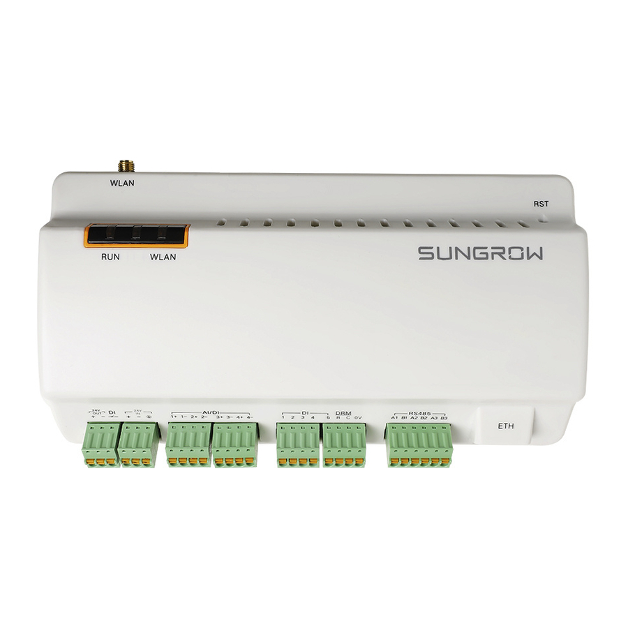
6 Electrical Connection 6.1 Safety Instructions Incorrect cable connection may cause device damage or even personal injury. All cables must be intact, well insulated, appropriately dimensioned, and firmly connected. 6.2 Port Introduction External wiring terminals are located at the bottom of Logger1000, and the wiring area is shown in the figure below. -
Page 26: Connection To Pv Devices
Devices in the PV system that can be connected to the Logger1000 include the inverter, Meteo Station, energy meter, etc. 6.3.1 Connection to Inverter Connection to a single inverter The RS485 port of SUNGROW inverter is RS485 terminal block or RJ45 port. RS485 terminal block connection Communication cable specification: Cable... - Page 27 User Manual 6 Electrical Connection Cable connection procedure: Lead the RS485 communication cable from the inverter to the wiring area of Step 1 Logger1000. Step 2 Strip the cable jacket and insulation layer with a wire stripper by about 15mm and 8mm to 10mm respectively. 0.75 mm 1.5 mm 8 ~ 10mm...
- Page 28 6 Electrical Connection User Manual Inverter Logger1000 RS485 A1 B1 PE A1 B1PE RJ45 port connection Communication cable specification: Cable Type Shielded twisted pair Ethernet cable RS485 communication cable Cable connection procedure: Step 1 Lead the RS485 communication cable from the inverter to the wiring area of Logger1000.
- Page 29 User Manual 6 Electrical Connection Logger1000 Inverter Connection to multiple devices Multiple inverters are connected to the Logger1000 in the RS485 daisy chain manner. If more than 15 inverters are connected on the RS485 bus, it is recommended to connect a 120Ω terminal resistor in parallel on the RS485A and RS485B lines at the head or tail end of the bus.
-
Page 30: Connection To Energy Meter
The addresses of devices on each RS485 bus must be different from one another and within the address range set for the Logger1000 (address range of residential inverters and string inverters manufactured by SUNGROW: 1-247; address range of third-party devices: 1-255). Otherwise, communication error will occur. -
Page 31: Connection To Background
User Manual 6 Electrical Connection Logger1000 Meteo Station Connect the communication cable led from the Meteo Station to the RS485 port of the Logger1000. If multiple inverters are connected to the Logger1000 together with the Meteo Station, the Meteo Station should be connected on the very end of the daisy chain. -
Page 32: Connection To Micro-Sim
6 Electrical Connection User Manual Fig. 6-2 Connection to PV background system Default IP of the "ETH": IP12.12.12.12. 6.5 Connection to Micro-SIM Support of hot plug of Micro-SIM. 6.6 Connection to Power Box The Logger1000 supports DC24V power supply. Prepare two-core DC cable, three-core AC cable, and grounding cable before wiring. - Page 33 User Manual 6 Electrical Connection Tab. 6-2 Power cable specification Length cable Length Recommended Cable jacket insulation cross-section stripped off stripped off DC cable, AC ~1.5mm 15mm 8mm~10mm cable Grounding ~1.5mm 8mm~10mm cable Power cable wiring steps are as follows: Step 1 Strip the cable jackets and insulation layers of the DC cable, AC cable, and grounding cable with a wire stripper by appropriate length.
-
Page 34: Cable Routing Requirements
6 Electrical Connection User Manual Step 4 Connect the DC cable led from the "24V IN" port of the Logger1000 to the "DC 24V OUT" port of the power box. Connect the stripped AC cable to the "AC (100~277V)" port of the power box, and connect the other end of the AC cable to the 220V AC power. - Page 35 User Manual 6 Electrical Connection shielded communication cables and power cables. Parallel cable length (m) Min. distance (m) The communication cables should be routed as closely to the ground surface or supports (such as support beam, steel channel, or metal rail) as possible.
-
Page 36: Commissioning
Set the devices connected to the Logger1000 through the device management function. If the device connected for the first time is SUNGROW string inverter, use "8.8.1 Device List" function to search □ the device whose address will be automatically allocated. For devices of other types, connect them to the Logger1000 by referring to "8.8.1 Device List". - Page 37 China access the "China Station", users in Europe access the "Europe Station", and users in other regions access the "International station". Check the data of SUNGROW string inverter for correctness on the □ real-time information interface. Create new plant via the iSolarCloud APP and check the □...
-
Page 38: Web Interface
8 Web Interface 8.1 Running Requirements Item Parameter Browser IE11 or later, Chrome65 or later, and Safari11 or later Min. resolution 1024*768 8.2 Login Steps The Web interfaces provided in this document are for reference only, and the actual ones may differ. Users of different types have different permissions. -
Page 39: Ethernet Login
After login for the first time, it is recommended to change the password as soon as possible. Click "O&M user" -> "Modify password" to change the password. With the login password forgot en, contact SUNGROW and provide the device S/N as well as system time, to get the password. 8.2.2 Ethernet Login... -
Page 40: Web Menu
8 Web Interface User Manual Item Designation Description Navigation menu Display main function modules of the Web Function display Display the current interface area Display the current alarm level and alarm number. Users Alarm icon can click the icons to enter the corresponding alarm interface Help Display the basic configuration steps of the Logger1000... -
Page 41: Operation Procedure
"8.10.5 System Time". Automatically search the device. Step 4 Devices that can be automatically searched, such as SUNGROW string inverter, can be added via the auto search function with addresses allocated automatically. Refer to the chapter “8.8.1 Device List”. -
Page 42: Overview
8 Web Interface User Manual After all devices have been added, configure the forwarding service of the Logger1000, to ensure that the Logger1000 can forward the data to upstream devices. Refer to the chapter "8.10.6 Forwarding Configuration". 8.6 Overview 8.6.1 General Information Click "Overview"... -
Page 43: Current Alarms
User Manual 8 Web Interface Inverter realtime values Information on the inverter such as state, daily yield, active power, and reactive can be viewed. 8.6.2 Current Alarms Click "Overview" -> "Current alarms" to view the device fault information. Information such as device name, alarm name, alarm type, alarm time, fault code, and fault ID can be viewed. -
Page 44: Protection Parameter
8 Web Interface User Manual Step 2 Click "Setting" to set initial parameters for the single device. Batch setting: Step 1 Select the desired country (region) and grid type. Step 2 Click "Configure synchronization". Select the desired devices in the pop-up device list, and click "Save" to Step 3 achieve batch setting. -
Page 45: Device Information
Logger1000 and configuring addresses for these devices. Devices can be automatically searched and added. Auto search The "Auto search" function is used for SUNGROW string inverter to which addresses will be automatically allocated. Click "Device" -> "Device list" to enter the corresponding interface. -
Page 46: Firmware Update
Step 3 Click "Confirm" in the pop-up window, to delete the device. 8.8.2 Firmware Update The firmware update function is used to upgrade the SUNGROW residential inverter and string inverter. Step 1 Click "Device" -> "Firmware update" to enter the corresponding interface. -
Page 47: Inverter Log
User Manual 8 Web Interface Step 4 Complete firmware update to view current version, target version, start time, end time and other information. The firmware file should be in the ".sgu" format. 8.8.3 Inverter Log Click "Device" -> "Inverter log" to enter the corresponding interface. Step 1 Select the device running information, and click the button to view the... -
Page 48: Remote Maintenance
8 Web Interface User Manual The upgrade file should be in the ".zip" format. Log export Click "System" -> "System maintenance" to enter the corresponding Step 1 interface. Click the button "Log export" to enter the corresponding interface. Step 2 Step 3 Select the type of logs to be exported, and click "Confirm". -
Page 49: Message Export
User Manual 8 Web Interface Remote maintenance switch state Description Logger1000 In case the remote maintenance switch is in the "Enable" state, the remote service address needs to be set. Users in mainland China select "iSolarCloud of China", users in Europe select "iSolarCloud of Europe", and users in other regions select the "iSolarCloud of International". -
Page 50: Forwarding Configuration
8 Web Interface User Manual Method of setting system time: When the option "Inverter timing" is selected, device time will be synchronized with the time of Logger1000. When the clock source is set to "User define", user can manually set the current system time and time zone in the following two manners: ... - Page 51 User Manual 8 Web Interface Click "System" -> "Transfer configuration" to enter the corresponding interface. iSolarCloud The default iSolarCloud station is "iSolarCloud of China". Users in mainland China select "iSolarCloud of China", users in Europe select "iSolarCloud of Europe", and users in other regions select the "iSolarCloud of International".
- Page 52 8 Web Interface User Manual Data Type Description Remote regulating Open the sheet "Cfg Para" of the IEC104 forwarding point table to view and Step 3 set the addresses of the five types of data. The addresses shown in the following table are default ones and can be modified according to actual situation.
- Page 53 User Manual 8 Web Interface Parameter Description Sort devices, and only support moving the whole line for the device type corresponds one-to-one to its parameters in the same line Device type Device Type Number of COM port to which device connected, corresponding Com ID* to the port data of the "Device list"...
-
Page 54: Interface
8 Web Interface User Manual Step 1 Click "System" -> "Transfer configuration" -> "Third-party portal" to enter the corresponding interface. Turn on the switch. Step 2 Click the button on the operation bar, so that an advanced setting Step 3 window will pop up. - Page 55 User Manual 8 Web Interface Mobile network Perform Mobile network setting on this interface. Click "System" -> "Interface" -> "Mobile network" to enter the corresponding Step 1 interface. After modifying the APN, username and password, click to save the Step 2 information.
-
Page 56: About
8 Web Interface User Manual Tab. 8-6 Description of AI parameter Parameter Default value Range 0 ~ 10 Voltage lower limit(V) 0 ~ 10 Voltage upper limit(V) 4 ~ 20 Current lower limit(mA) 4 ~ 20 Current upper limit(mA) Click "System" -> "Interface" -> "DI" to enter the corresponding interface. Step 1 Step 2 Set the initial status to "NO"... -
Page 57: Grid Dispatching Function
PV array/plant, but also has the power regulation function. Multiple regulation manners can meet different regulation requirements. The Logger1000 can regulate the power output of the SUNGROW inverter, and the regulation mainly includes active power control and reactive power regulation. -
Page 58: Interface Description
9 Grid Dispatching Function User Manual The corresponding power dispatching function is available only when the inverter supports active power control, power factor control, and reactive power regulation! For details, refer to the inverter user manual or consult the local retailer. 9.2 Interface Description The Logger1000 is equipped with digital control interfaces and analog control interfaces for receiving digital instructions and analog instructions sent by the grid... - Page 59 User Manual 9 Grid Dispatching Function Logger1000 Wireless receiver controller In Germany and some other European countries, the grid company uses the Ripple Control Receiver to convert the grid dispatching signal and send it in a dry contact manner, In this case, the plant needs to receive the grid dispatching signal in the dry contact communication manner.
-
Page 60: Analog Control Interface
9 Grid Dispatching Function User Manual Logger1000 Ripple Control Receiver DI 1+ DI 1- DI 2+ DI 2- DI 3+ DI 3- DI 4+ DI 4- 24 OUT- 24 OUT+ 9.2.2 Analog Control Interface The analog control interfaces are at the bottom of the Logger1000, and a sum of 4 analog input ports are provided, as shown in the figure below. -
Page 61: Power Control
User Manual 9 Grid Dispatching Function Logger1000 DRED The DRM interface requires that the Logger1000 can be connected to the DRED via the corresponding wiring terminal or RJ45 connector. 9.3 Power Control Power regulation includes active power control and reactive power regulation. 9.3.1 Active Power Disable If the inverter needs to operate at full load, the active control mode should be set to... - Page 62 9 Grid Dispatching Function User Manual Parameter Description sent to the power output port of the inverter, thereby achieving active power control. Closed-loop control: 1) In case no energy meter is selected, remote monitoring background connected, active instruction of remote dispatching is used as target value, and active power compensation ratio is calculated and sent to the power output port of the inverter.
- Page 63 User Manual 9 Grid Dispatching Function Parameter Description Closed-loop control: 1) In case no energy meter is selected, at the beginning time, the active instruction configured locally is used as target value, and active power compensation ratio is calculated and sent to the power output port of the inverter.
- Page 64 9 Grid Dispatching Function User Manual Parameter Description abnormality output (%) output value is delivered. Open loop control: Active instruction controlled by AI is sent to the power output port of the inverter, thereby achieving active power control. Closed-loop control: 1)...
- Page 65 User Manual 9 Grid Dispatching Function Tab. 9-6 Parameter description Parameter Description Communication Communication is abnormal, and specified dispatch abnormality output (%) output value is delivered. Open loop control: Active instruction controlled by DI is sent to the power output port of the inverter, thereby achieving active power control.
-
Page 66: Reactive Power
9 Grid Dispatching Function User Manual 9.3.2 Reactive Power Disable If the grid company does not need the power plant to adjust the voltage at the grid-connection point, and the inverter does not need to cooperate with the grid for reactive power compensation,... - Page 67 User Manual 9 Grid Dispatching Function Step 4 After finishing parameter setting, click "Save" to save the operation. Local power control If reactive dispatching instruction or dispatching target value is used as dispatching input locally, the reactive control mode is set to "Local power control". Click "Power control"...
- Page 68 9 Grid Dispatching Function User Manual AI control When using the analog signal at the AI port of the Logger1000 as the dispatching input, set the reactive control mode to "Analog input". Step 1 Click "Power control" -> "Reactive power" to enter the reactive power interface.
- Page 69 User Manual 9 Grid Dispatching Function Step 4 After finishing parameter setting, click "Save" to save the operation. Digital input When using the digital signal at the DI port of the Logger1000 as the dispatching input, set the reactive control mode to "Digital input". Click "Power control"...
-
Page 70: Emergency Button
9 Grid Dispatching Function User Manual 9.3.3 Emergency Button In inverters need to be stopped in batch, select the button "Emergency button". Click "Power control" -> "Emergency button" to enter the corresponding interface. Parameter Description Enable: The emergency button is turned on, and inverters are stopped in batch. -
Page 71: Device Maintenance
10 Device Maintenance Due to the effect of ambient temperature, humidity, dust and vibration, the inner components of the Logger1000 will be aging and worn out. To ensure the system safety and maintain the efficiency of the Logger1000, it is necessary to carry out routine and periodic maintenance. -
Page 72: Maintenance
The grounding cable must be grounded reliably. Otherwise, electric shock can cause personal injury! The common faults and troubleshooting is shown in the table below. If the problem still cannot be removed by following the instruction in this manual, please contact SUNGROW. - Page 73 Power-on has no power connection Logger1000 fault 2. Power source failure 2. Replace the power source 3. Logger1000 fault 3. Contact SUNGROW 1. The RS485 port is not connected to any devices or the connection cable is loose connected reversely.
-
Page 74: Appendix
Mechanical Parameters Dimensions (W x H x D) 200 x 110 x 60 mm Weight 500 g Mounting type Top-hat rail mounting/ wall mounting 11.2 Quality Guarantee SUNGROW shall service or replace the faulty product for free within the warranty... - Page 75 The damage is caused by unpredictable factors For the foregoing faults or damages, SUNGROW can provide a paid service at the request of the client after judgment. The dimensions and parameters of the device are subject to changes without notification, and reference can be made to the latest document.
-
Page 76: Contact Information
Serial number of the device Fault code/name Brief description of the problem China (HQ) Australia Sungrow Power Supply Co., Ltd Sungrow Australia Group Pty. Ltd. Hefei Sydney +86 551 65327834 +61 2 9922 1522 service@sungrowpower.com service@sungrowpower.com.au Brazil... - Page 77 Tokyo Seoul + 81 3 6262 9917 +82 70 7719 1889 japanservice@jp.sungrowpower.com service@kr.sungrowpower.com Malaysia Philippines Sungrow SEA Sungrow Power Supply Co., Ltd Selangor Darul Ehsan Mandaluyong City +60 19 897 3360 +63 9173022769 service@my.sungrowpower.com service@ph.sungrowpower.com Thailand Spain Sungrow Thailand Co., Ltd.
- Page 78 11 Appendix User Manual U.S.A, Mexico Sungrow Power UK Ltd. Sungrow USA Corporation Milton Keynes Phoenix Arizona +44 (0) 0908 414127 +1 833 747 6937 service.uk@sungrow.co techsupport@sungrow-na.com Vietnam Sungrow Vietnam Hanoi +84 918 402 140 service@vn.sungrowpower.com...
Need help?
Do you have a question about the 1000A and is the answer not in the manual?
Questions and answers