
Related Manuals for Emerson Rosemount 2230


Summary of Contents for Emerson Rosemount 2230
- Page 1 Reference Manual 00809-0100-2230, Rev DA March 2021 ™ Rosemount 2230 Graphical Field Display...
- Page 2 Read this manual before working with the product. For personal and system safety, and for optimum product performance, ensure you thoroughly understand the contents before installing, using, or maintaining this product. For equipment service or support needs, contact your local Emerson Automation Solutions/Rosemount Tank Gauging representative.
-
Page 3: Table Of Contents
4.8 F Fieldbus overview....................69 OUNDATION 4.9 Device capabilities........................71 4.10 General block information....................... 72 4.11 Factory configuration......................73 4.12 Multiple Analog Output blocks....................74 4.13 Resource block........................78 4.14 475 Field Communicator menu tree..................84 Rosemount 2230 Graphical Field Display... - Page 4 Contents Reference Manual March 2021 00809-0100-2230 4.15 Configuration using AMS Device Manager................85 4.16 Configure and enable/disable alerts..................94 Chapter 5 Service and troubleshooting..................97 5.1 Safety messages........................97 5.2 Service............................98 5.3 Troubleshooting........................103 5.4 Resource block error messages....................113 5.5 Transducer block error messages.....................113 5.6 Alerts............................
- Page 5 Reference Manual Contents 00809-0100-2230 March 2021 C.5 Multiple Analog Output block....................172 C.6 Supported units........................174 Rosemount 2230 Graphical Field Display...
- Page 6 Contents Reference Manual March 2021 00809-0100-2230 Reference Manual...
-
Page 7: Chapter 1 Introduction
Use extreme caution when making contact with the leads and terminals. WARNING Any substitution of non-recognized parts may jeopardize safety. Repair (e.g. substitution of components) may also jeopardize safety and is not allowed under any circumstances. Rosemount 2230 Graphical Field Display... -
Page 8: Symbols
Specifications and reference data contains specifications, dimensional drawings, and ordering table. Appendix Product certifications contains information on approvals and certifications. ™ Appendix Fieldbus Block Information describes the various function and OUNDATION transducer blocks which are used for the Rosemount 2230. Reference Manual... -
Page 9: Technical Documentation
March 2021 Technical documentation ™ The Rosemount Tank Gauging System includes a wide portfolio of user documentation. For a complete list, see product pages on Emerson.com/Rosemount. Reference manuals • Rosemount Tank Gauging System Configuration Manual (00809-0300-5100) • Rosemount 2460 System Hub (00809-0100-2460) •... -
Page 10: Product Recycling/Disposal
Rosemount 2230 Product Data Sheet (00813-0100-2230) • Rosemount 5300 Product Data Sheet (00813-0100-4530) • Rosemount 5408 Product Data Sheet (00813-0100-4408) Drawings Table 1-2: Installation Drawings for the Rosemount 2230 Graphical Field Display Drawing Title D7000003-838 Mechanical Installation Drawing 2230 D9240041-953 Electrical Installation Drawing 2230 Display ™... - Page 11 When burning interior plywood the nitrogen in the adhesives may increase emissions of nitrogen oxides to the air 3-4 times more than when burning bark and splinter. Note Landfill is not a recycling option and should be avoided. Rosemount 2230 Graphical Field Display...
- Page 12 Introduction Reference Manual March 2021 00809-0100-2230 Reference Manual...
-
Page 13: Chapter 2 Overview
Hub allows you to view data from several tanks. It is possible to configure presentation of measurement variables for each tank individually. The four softkeys at the front of the Rosemount 2230 allow you to navigate through the different menus and provides all tank data, directly in the field. -
Page 14: Components
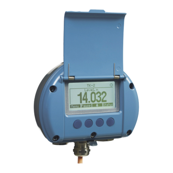
In case no 2460 is included in the system, the Rosemount 2410 Tank Hub can communicate directly with the host computer. Components Figure 2-2: Rosemount 2230 Components A. Weather protection lid B. Display C. Menu D. -
Page 15: System Overview
The flexible Rosemount Tank Gauging system supports several combinations to achieve redundancy, from control room to the different field devices. Redundant network configuration can be achieved at all levels by doubling each unit and using multiple control room work stations. See documents IEC 61158-2 Rosemount 2230 Graphical Field Display... - Page 16 TRL2 Modbus Rosemount 5900S Radar Level Gauge Segment coupler Rosemount 2240S Temperature Transmitter Rosemount 644 Temperature Transmitter Rosemount 2230 Graphical Field Display Rosemount 5300 Level Transmitter Rosemount 2410 Tank Hub Rosemount 5408 Level Transmitter Rosemount 3051S Pressure Transmitter Custody transfer / Inventory tank gauging...
- Page 17 G. Emerson Wireless 775 THUM Adapter H. Rosemount 5900S Radar Level Gauge I. Rosemount 2240S Temperature Transmitter J. Rosemount 3051S Pressure Transmitter K. Rosemount 2230 Graphical Field Display L. Segment coupler M. Rosemount 644 Temperature Transmitter Rosemount 2230 Graphical Field Display...
- Page 18 Fieldbus Power Supply OUNDATION Rosemount 5900S Radar Level Gauge Segment coupler Rosemount 2240S Temperature Transmitter Rosemount 5300 Level Transmitter Rosemount 5408 Level Transmitter Rosemount 2230 Graphical Field Display Custody transfer / Inventory tank gauging Rosemount 3051S Pressure Transmitter Operational control Reference Manual...
- Page 19 The Rosemount 2410 Tank Hub acts as a power supply to the connected field devices in the hazardous area using the intrinsically safe Tankbus. The tank hub collects measurement data and status information from field devices on a tank. It has two external buses for communication with various host systems. Rosemount 2230 Graphical Field Display...
- Page 20 The Rosemount 2410 supports Intrinsically Safe (IS) and Non-Intrinsically Safe (Non-IS) analog 4-20 mA inputs/outputs. By connecting an Emerson Wireless 775 THUM Adapter to the IS HART 4-20 mA output, the tank hub is capable of wireless communication with an ®...
-
Page 21: System Start-Up
The four softkeys allow you to navigate through the different menus to provide all tank data, directly in the field. The Rosemount 2230 supports up to 10 tanks. Up to three Rosemount 2230 displays can be used on a single tank. - Page 22 3. Verify that the total current consumption of devices connected to the Tankbus does not exceed 250 mA . In an Emerson Wireless system the maximum current is 200 4. Wire the devices. a) Connect field devices to the Tankbus.
-
Page 23: Installation Procedure
(Document No. 00809-0300-5100) for more information on how to configure various Rosemount Tank Gauging devices. Related information Technical documentation Installation procedure Follow these steps for proper installation of the Rosemount 2230 Graphical Field Display: Procedure 1. Review installation considerations (Installation considerations). - Page 24 Overview Reference Manual March 2021 00809-0100-2230 Reference Manual...
-
Page 25: Chapter 3 Installation
The Rosemount 2230 is designed for mounting on a wall or a pipe. It is important to provide space for opening the weather protection lid which prevents degradation of the LCD display due to sunlight exposure. -
Page 26: Mechanical Installation
Figure 3-1: Space Required for Opening the Lid A. Weather protection (optional) B. 93 mm (3.7 in.) Related information Components Mechanical installation 3.3.1 Mounting the graphical display The Rosemount 2230 Graphical Field Display is designed for mounting on a wall or a pipe. Reference Manual... - Page 27 Countersunk screws are not suitable. 70 mm (2.7 in.) Ø 9mm (0.35 in.) 94 mm (3.7 in.) 2. Attach the Rosemount 2230 display to the bracket on the wall by sliding it from the top downwards. A. Locking screw B. Bracket 3.
- Page 28 Automation Solutions/Rosemount Tank Gauging. Procedure 1. Attach the bracket to the pipe. Ensure that the Rosemount 2230 is placed in a direction so that the display is clearly visible and wiring can be properly connected. A. 1 - 2 inches B.
-
Page 29: Electrical Installation
There is an external grounding screw located at the bottom of the housing and an internal grounding screw located inside the housing, see Figure 3-2. The internal ground screw is identified by a ground symbol: Figure 3-2: Grounding Screws A. Internal ground B. External ground. Cable diameter minimum 4 mm Rosemount 2230 Graphical Field Display... - Page 30 3.4.3 Cable selection Use shielded twisted pair wiring for the Rosemount 2230 in order to comply with FISCO requirements and EMC regulations. The cables must be approved for use in hazardous areas, where applicable. In the U.S. explosion-proof conduits may be used in the vicinity of the vessel.
- Page 31 The Rosemount 2230 is powered over the intrinsically safe Tankbus by the Rosemount 2410 Tank Hub. The 2410 feeds the intrinsically safe fieldbus segment by acting as a FISCO power supply on the Tankbus (9 - 17.5 Vdc, polarity insensitive). The Rosemount 2230 has a current consumption of 30 mA.
- Page 32 Installation Reference Manual March 2021 00809-0100-2230 Segment design When designing a FISCO fieldbus segment a few requirements need to be considered. Cabling has to comply with FISCO requirements. You will also have to ensure that the total operating current of the connected field devices is within the output capability of the Rosemount 2410 Tank Hub.
- Page 33 OUNDATION integrate it into an existing FF network. As long as the power supply meets certain requirements (see Figure 3-4 Figure 3-5) the Rosemount 2230 will be able to operate as any other FF device. Rosemount 2230 Graphical Field Display...
- Page 34 Figure 3-4: Example of an I.S. F Fieldbus System OUNDATION A. I.S. Power Supply B. Trunk C. Rosemount 2230 Display D. Segment Coupler E. Rosemount 644 Temperature Transmitter F. Rosemount 5900S Radar Level Gauge Figure 3-5: Example of a Non-I.S. F...
- Page 35 FB-. 5. Connect the cable shield to the “Shield Loop Through” (X1) terminal. 6. If the Rosemount 2230 display is the last device on the Tankbus, connect a jumper for the built-in termination. 7. Replace the cover. Make sure that the sealing and the locking device for the weather protection hatch are placed in the correct positions.
- Page 36 E. Jumper for built-in termination F. X4: Tankbus terminator G. Daisy-chain connection to other field devices Related information Daisy-chain connection Daisy-chain connection The Rosemount 2230 can be daisy-chained to other field devices via the Tankbus, see Figure 3-7. Reference Manual...
- Page 37 F. Tankbus G. Built-in terminator enabled on the last device Procedure 1. Unscrew and remove all six screws on the front of the Rosemount 2230. 2. Remove the cover carefully. Take care of the locking device for the weather protection hatch.
-
Page 38: Led Signals And Reset Button
8. Firmly tighten the six screws on the front cover. LED signals and reset button The Rosemount 2230 has three LED signals that show communication and status. Figure 3-9: LED Signals A. Reset button B. -
Page 39: Dip Switches
Tankbus cables you can check the communication status with the LEDs. Reset button You may use the Reset button to force a restart of the Rosemount 2230 display. Restarting the Rosemount 2230 has the same effect as switching off and on the power supply. -
Page 40: Ambient Temperature
The Simulate switch is used for simulation of Field Diagnostics conditions. It may be useful when testing the alarm setup. Write protect switch The Write Protect switch can be used to protect the Rosemount 2230 from unintentional changes of the current configuration. Related information... -
Page 41: Configuration And Operation
Before connecting a handheld communicator in an explosive atmosphere, ensure that the instruments in the loop are installed in accordance with intrinsically safe or non- incendive field wiring practices. • Do not remove the cover in explosive atmospheres when the circuit is alive. Rosemount 2230 Graphical Field Display... -
Page 42: Introduction
(Document no. 00809-0300-5100). 4.2.1 The Rosemount 2230 Graphical Field Display The Rosemount 2230 is a graphical display designed for viewing tank data in tough environments. It features adjustable LCD contrast, backlight, multi-language support, and communication failure indication. ™ The Rosemount 2230 can be used in systems based on the Rosemount 2410 Tank Hub as ™... - Page 43 Status Lets you view the current status of the presented measurement variable. A symbol in the upper right-hand corner of the display indicates that the Rosemount 2230 is operating and communicates on the Tankbus. Adjust the display contrast The Rosemount 2230 automatically adjusts display contrast to optimize for changes of ambient temperature.
- Page 44 Configuration and operation Reference Manual March 2021 00809-0100-2230 4.2.3 Activity and alarm indication The Rosemount 2230 display shows an alarm warning symbol for simulated or manual measurement values as illustrated in Figure 4-2 Figure 4-3. Figure 4-2: Simulated or Manual Value A.
- Page 45 After the LCD test is done the start-up screen will appear. Figure 4-6: Start-up Screen Once the start-up procedure is finished, the Rosemount 2230 will return to the view that was used last time the display was powered on. Figure 4-7: View Mode...
-
Page 46: Menu Tree
Configuration and operation Reference Manual March 2021 00809-0100-2230 Menu tree The Rosemount 2230 lets you navigate in a menu structure as illustrated in Figure 4-8. Figure 4-8: Rosemount 2230 Menu Tree Reference Manual... -
Page 47: Main Menu
00809-0100-2230 March 2021 Main menu In normal operation the Rosemount 2230 display is in View Mode and shows the current measurement values for the selected tanks. In case of an alarm, a graphical symbol appears on the screen. Figure 4-9: Rosemount 2230 Graphical Field Display in View Mode A. -
Page 48: Select The Number Of Data Fields
Example 5. Press the OK softkey to select the desired option. Then the Rosemount 2230 returns to View Mode. Example For example, using the Two Values option will present a view like this: Reference Manual... -
Page 49: Options Menu
Reference Manual Configuration and operation 00809-0100-2230 March 2021 Options menu In the Options menu, the following items are available for a Rosemount 2230 connected to a Rosemount 2410 Tank Hub: (10) • Variables (10) • Tanks • Units for Display •... - Page 50 Configuration and operation Reference Manual March 2021 00809-0100-2230 4.6.1 Choose an item in the options menu Procedure 1. In View Mode, press the Menu button to open the Main menu. 2. Highlight the Options menu item by using the softkeys. 3.
- Page 51 4. In the Select Variables list, choose the variables you wish to show in View Mode. 5. When finished, press OK to return to View Mode. ™ (11) Not available in F Fieldbus systems. OUNDATION Rosemount 2230 Graphical Field Display...
- Page 52 Configuration and operation Reference Manual March 2021 00809-0100-2230 Table 4-2: Selectable Variables Variable Description Level Product level in the displayed tank Ullage Ullage is the distance from the Tank Reference Point to the product surface Level Rate How the product in the tank moves when emptying or filling the tank Signal Strength The signal strength of the radar level gauge...
- Page 53 5. Press the On/Off softkey to select the tank. 6. When finished, press the OK softkey to return to View Mode. ™ (12) Not available in F Fieldbus systems. OUNDATION (13) See the Rosemount 2410 Tank Hub Reference Manual (Document no. 00809-0100-2410). Rosemount 2230 Graphical Field Display...
- Page 54 Configuration and operation Reference Manual March 2021 00809-0100-2230 4.6.4 Set the measurement units for displayed variables In the Units for Display menu, you can see which measurement units that are used for the displayed variables. To change measurement unit: Procedure 1.
- Page 55 Reference Manual Configuration and operation 00809-0100-2230 March 2021 Measurement units Table 4-3: Available Measurement Units for the Rosemount 2230 Variable Available Measurement Units Auto The display is controlled by the Multiple Analog Output Block configuration. Length The following units are available for Level and Ullage: •...
- Page 56 Configuration and operation Reference Manual March 2021 00809-0100-2230 Table 4-3: Available Measurement Units for the Rosemount 2230 (continued) Variable Available Measurement Units Pressure The following units are available for Pressure: • • Pascal • Kilo pascal • Atmosphere • •...
- Page 57 1. From View Mode, press Menu → Options → Toggle Time. 2. Use the softkeys to increase or decrease the Toggle Time. 3. Press the OK softkey to select the desired value and return to View Mode. Rosemount 2230 Graphical Field Display...
- Page 58 Configuration and operation Reference Manual March 2021 00809-0100-2230 4.6.6 Set the display language Procedure 1. From View Mode, press Menu → Options → Language. 2. Use the softkeys and navigate to the preferred language option: 3. Press the OK softkey to select the language and return to View Mode. Reference Manual...
-
Page 59: Service Menu
In the Service Menu, the following items are available: • Status (14) • Custody Transfer View • Start Proof Test • LCD Test • LCD Contrast • Restart (14) • Factory Settings • About ™ (14) Not available in F Fieldbus systems OUNDATION Rosemount 2230 Graphical Field Display... - Page 60 Configuration and operation Reference Manual March 2021 00809-0100-2230 4.7.1 Choose a service menu item Procedure 1. In View Mode, press the Menu button to open the Main menu. 2. Use the softkeys to navigate to the Service option. 3. Press the softkey.
- Page 61 March 2021 4.7.2 View the current device status The Status screen shows the current status of the Rosemount 2230. Various error messages and warnings can be displayed in case of software or hardware malfunctions. Procedure 1. In the View Mode, press Menu → Service → Status.
- Page 62 Configuration and operation Reference Manual March 2021 00809-0100-2230 4.7.3 Open the custody transfer view The Custody Transfer view presents Level and Liquid Temperature for each tank. Procedure In View Mode, press Menu → Service → Custody Transfer. • Press the Esc softkey to return to View Mode. Press the Pause softkey to pause the display toggling.
- Page 63 2. Select the Service option. 3. Select Start proof test. 4. Enter the password. Note that default password is “000”. 5. Choose the desired tank. 6. Select OK to continue and follow the instructions on the display. Rosemount 2230 Graphical Field Display...
- Page 64 Configuration and operation Reference Manual March 2021 00809-0100-2230 4.7.5 Open the LCD test view In the LCD test two checkered patterns will be displayed testing the whole display area. Procedure In View Mode, press Menu → Service → LCD Test. After the test is completed, the display will return to normal View Mode.
- Page 65 00809-0100-2230 March 2021 4.7.6 Adjust the LCD contrast The Rosemount 2230 automatically adjusts display contrast to optimize for changes of ambient temperature. The contrast can be manually adjusted when further fine-tuning is desired. Procedure 1. In View Mode, press Menu → Service → LCD Contrast.
- Page 66 4.7.7 Restart the Rosemount 2230 The Restart option will perform start-up tests of software and hardware. In a Rosemount Tank Gauging system it will connect the Rosemount 2230 to the Rosemount 2410 Tank Hub. Procedure 1. In View Mode, press Menu → Service.
- Page 67 1. In View Mode, press Menu → Service. 2. Choose the Factory Settings option and press the softkey. 3. Press the OK softkey to restore the Rosemount 2230 to factory settings, or press the Esc softkey to cancel. Rosemount 2230 Graphical Field Display...
- Page 68 March 2021 00809-0100-2230 4.7.9 View the about information The About option will present the current software version and the Rosemount 2230 serial number. Procedure 1. In View Mode, press Menu → Service. 2. Choose the About option and press the softkey.
-
Page 69: Foundation
There are no linkable inputs or outputs to the resource block. Main transducer block (TB1100) The Main Transducer Block contains parameters for configuration of the Rosemount 2230. It contains device information including diagnostics and the ability to configure, set to factory defaults and restart the Rosemount 2230. - Page 70 March 2021 00809-0100-2230 Display transducer block (TB1300) The Display Transducer Block includes parameters for setup of the Rosemount 2230 for use in a Fieldbus system. It handles mapping of the MAO block inputs to the various field device outputs. Reference Manual...
-
Page 71: Device Capabilities
4.9.1 Link Active Scheduler The Rosemount 2230 can be designated to act as the backup Link Active Scheduler (LAS) in the event that the LAS is disconnected from the segment. As the backup LAS, the Rosemount 2230 will take over the management of communications until the host is restored. -
Page 72: General Block Information
Configuration and operation Reference Manual March 2021 00809-0100-2230 4.10 General block information 4.10.1 Modes Changing modes To change the operating mode, set the MODE_BLK.TARGET to the desired mode. After a short delay, the parameter MODE_BLOCK.ACTUAL should reflect the mode change if the block is operating properly. -
Page 73: Factory Configuration
Reference Manual Configuration and operation 00809-0100-2230 March 2021 4.11 Factory configuration The following fixed configuration of function blocks is provided: Table 4-6: Available Function Blocks for the Rosemount 2230 Function Block Index Default Tag Available Multiple Analog Output 1400 MAO_1400... -
Page 74: Multiple Analog Output Blocks
Reference Manual March 2021 00809-0100-2230 4.12 Multiple Analog Output blocks To show input data from MAO blocks on the display, the Rosemount 2230 needs to be ™ configured by using F Fieldbus parameters which are available in the Display OUNDATION Transducer Block. - Page 75 Product Level is output from the Rosemount 5900S via an Analog Input block to the Multiple Analog Output Block 1 (FFMAO1) in the Rosemount 2230 display, as well as to the Analog Output Block (FFAO_RMT7) in the Rosemount 2240S Temperature Transmitter, for Average Product Temperature calculations.
- Page 76 Configuration and operation Reference Manual March 2021 00809-0100-2230 configured by using AMS Device Manager as shown in Figure 4-13. MAO Block 1 is configured for Level, Liquid Temperature, and Free Water Level. Figure 4-13: MAO Block 1 MAO Block 2 is configured for Temperature inputs 1 to 6. Reference Manual...
- Page 77 Reference Manual Configuration and operation 00809-0100-2230 March 2021 Figure 4-14: MAO Block 2 Related information Configuration using AMS Device Manager Rosemount 2230 Graphical Field Display...
-
Page 78: Resource Block
Unicode octet strings, you must set the Unicode option bit. REPORTS The Rosemount 2230 supports alert reports. The Reports option bit must be set in the features bit string to use this feature. If it is not set, the host must poll for alerts. If this bit is set, the transmitter will actively report alerts. - Page 79 FD_FAIL_MAP This parameter maps conditions to be detected as active for this alarm category. Thus the same condition may be active in all, some, or none of the four alarm categories. The Rosemount 2230 Graphical Field Display...
- Page 80 Configuration and operation Reference Manual March 2021 00809-0100-2230 parameter contains a list of conditions in the device which makes the device non- operational that will cause an alarm to be sent. Below is a list of the conditions with the highest priority first.
- Page 81 MAINT_PRI parameter described below. It is hard coded within the device and is not user configurable. Note that maintenance alarms are not enabled by default for the Rosemount 2230. FD_MAINT_MASK The FD_MAINT_MASK parameter will mask any of the failed conditions listed in FD_MAINT_MAP.
- Page 82 Configuration and operation Reference Manual March 2021 00809-0100-2230 Related information Alarm priority Function check alerts A Function Check alert indicates that the device is temporary non-valid due to some activities, for example maintenance, on the device. There are five parameters associated with Function Check alerts, they are described below. FD_CHECK_MAP The FD_CHECK_MAP parameter contains a list of informative conditions that do not have a direct impact on the primary functions of the device.
- Page 83 (such as diagnostics and system alerts). Alarm conditions of priority 3 to 7 are advisory alarms of increasing priority. 8-15 Alarm conditions of priority 8 to 15 are critical alarms of increasing priority. Rosemount 2230 Graphical Field Display...
-
Page 84: 475 Field Communicator Menu Tree
March 2021 00809-0100-2230 4.14 475 Field Communicator menu tree The Rosemount 2230 can be configured by using a 475 Field Communicator. Figure 4-15 shows the available options for configuration and service. Figure 4-15: Field Communicator Menu Tree 1 Device Status... -
Page 85: Configuration Using Ams Device Manager
March 2021 4.15 Configuration using AMS Device Manager The Rosemount 2230 Graphical Field Display supports DD Methods to facilitate device configuration. The following description shows how to use the AMS Device Manager ™ application to configure the Rosemount 2230 in a F Fieldbus system. - Page 86 Configuration and operation Reference Manual March 2021 00809-0100-2230 4. Select the Overview option. The Overview window shows information about the current device status: Good or Bad. It also gives you access to more device information by clicking the Device Information button. 5.
- Page 87 The Multiple Analog Output Block window lets you map tanks and tank parameters from the Multiple Analog Output (MAO) block inputs 1 - 8 to the tanks and tank parameters in the Rosemount 2230 transducer block. This configuration is required in order to make the field device parameters available on the display output.
- Page 88 Configuration and operation Reference Manual March 2021 00809-0100-2230 The Bar Graph Minimum and Maximum Value correspond to 0 % and 100 %, respectively. In case you don’t want any bar graph to be displayed simply leave Minimum Value=0 and Maximum Value=0. Note that tank names can be configured in the Manual Setup window.
- Page 89 This window lets you specify names for various custom parameters: • The Long Custom Parameter Name is used for the Single Value view and the Two Values View on the Rosemount 2230 display. It may be up to 20 characters long. •...
- Page 90 Configuration and operation Reference Manual March 2021 00809-0100-2230 7. Proceed with configuration of custom units by clicking the Custom Units button. In the Custom Units window specify units for the various custom parameters. The unit label can be specified anyway you like. It does not need to be a standard unit such as metric or imperial units.
- Page 91 5. Select the Configure → Manual Setup option. 6. Set the device to Out Of Service (OOS) mode by clicking the Change button. 7. Select the desired tab (Device, Multiple Analog Output Block Mapping, Tank Name etc.) and configure the device. Rosemount 2230 Graphical Field Display...
- Page 92 00809-0100-2230 The Device tab lets you configure display units, display view and language. It also provides the option to write protect the Rosemount 2230. In addition to the Device tab there are various tabs that give you access to options such as block parameter mapping, configuration of custom parameters and units, as well as tank name specification.
- Page 93 Reference Manual Configuration and operation 00809-0100-2230 March 2021 Figure 4-17: Classic View Related information Resource block Main transducer block (TB1100) Display transducer block (TB1300) Register transducer block (TB1200) Rosemount 2230 Graphical Field Display...
-
Page 94: Configure And Enable/Disable Alerts
Configuration and operation Reference Manual March 2021 00809-0100-2230 4.16 Configure and enable/disable alerts The Alert Setup window allows you to configure and enable/disable alerts. Procedure 1. From the Start menu, open the AMS Device Manager application. 2. Open the View → Device Explorer and select the appropriate network node (in the example below SEGOT01-110111). - Page 95 4.16.1 Alert default settings The following default settings are used for the FF I/O Board and the Rosemount 2230 Graphical Field Display. You may configure error types in a different way if you like. For example, the Internal Temperature Out of Limits error is configured as a Out of Specification alert for the Rosemount 2230 by default.
- Page 96 Enabled Internal communication failure Failed alert Enabled Electronics failure FF I/O Board Failed alert Enabled Table 4-10: Default Alert Configuration for Rosemount 2230 Error type Default configuration Enabled / Disabled Internal Temperature Out of Limits Out of Specification alert Enabled...
-
Page 97: Service And Troubleshooting
Before connecting a handheld communicator in an explosive atmosphere, ensure that the instruments in the loop are installed in accordance with intrinsically safe or non- incendive field wiring practices. • Do not remove the cover in explosive atmospheres when the circuit is alive. Rosemount 2230 Graphical Field Display... -
Page 98: Service
1. In the View Mode, press Menu → Service → Status. 2. Press Esc to return to the Service menu. Related information Status messages Status messages Various Status messages that may appear on the Rosemount 2230 display are listed in Table 5-1. Table 5-1: Status Information Status Message... - Page 99 7. In the Show Values in pane, choose the appropriate register format Decimal or Hexadecimal. 8. Click the Read button. Now the View Input/Holding Registers window is updated with the current register values. Related information Viewing input/holding registers using AMS Device Manager Rosemount 2230 Graphical Field Display...
- Page 100 O-rings are available as spare parts. Related information Restart the Rosemount 2230 5.2.4 Device error signals A Light Emitting Diode (LED) inside the Rosemount 2230 cover is used for presentation of device status using different blinking sequences. Reference Manual...
- Page 101 Only the first detected error is indicated. Note Ensure that o-rings and seats are in good condition prior to mounting the cover in order to maintain the specified level of ingress protection. Cables must be properly attached to the Rosemount 2230 Graphical Field Display...
- Page 102 Service and troubleshooting Reference Manual March 2021 00809-0100-2230 cable glands. It is recommended that the O-ring is changed when the cover is opened. O- rings are available as spare parts. Related information Device errors Reference Manual...
-
Page 103: Troubleshooting
March 2021 Troubleshooting 5.3.1 Troubleshooting the Rosemount 2230 Table 5-3 provides summarized maintenance and troubleshooting suggestions for the most common operating problems. Table 5-3: Troubleshooting Chart for the Rosemount 2230 Display Symptom Possible cause Action No communication Wiring • Check that wires are properly connected to... - Page 104 Service and troubleshooting Reference Manual March 2021 00809-0100-2230 Table 5-3: Troubleshooting Chart for the Rosemount 2230 Display (continued) Symptom Possible cause Action Software failure • Restart the Rosemount 2230. Use for example the Restart command in TankMaster WinSetup. • Restart all devices by disconnecting and...
- Page 105 Rosemount 2460 System Hub field ports. • Check that the correct communication channel is selected. See the Rosemount Tank Gauging System Configuration Manual (Document no. 00809-0300-5100) for more information on how to configure the system hub. Rosemount 2230 Graphical Field Display...
- Page 106 2160 Field address specified for the ATD device that Communication Unit (FCU) represents the Rosemount 2230 display in the 2160 FCU Slave Database. For the single tank version, the ATD address is equal to the Modbus address of the Rosemount 2410 Tank Hub itself.
- Page 107 • Check communication port LED:s inside the Field Communication Unit 2160 (FCU) Activity indicator Communication failure Check that the Rosemount 2230 is shows a warning configured in the Rosemount 2410 tank symbol database. See the Rosemount Tank Gauging System Configuration Manual (Document no.
- Page 108 5.3.4 Device errors Table 5-6 shows a list of error messages for the Rosemount 2230. Detailed information about the different error types can be found in Input registers 1100 - 1134 as shown in Table 5-6. Table 5-6: Device Errors...
- Page 109 Bit 1: Communication error with temp chip Bit 2: Device error Measurement Error Input register no. 1122. Not used Configuration Error Input register no. 1124. Choose a supported measurement unit Bit 1: Unit Not Supported Rosemount 2230 Graphical Field Display...
- Page 110 Register database of the Rosemount 2410 Tank Hub. The Input Registers presented in TankMaster WinSetup refer to the internal register area of the Rosemount 2410. Therefore, for tank 1 you will have to add 16000 to the Rosemount 2230 internal register number as given by Table 5-6 in order to find the register presented by WinSetup.
- Page 111 String Bit 12: Invalid Model Code The register number refers to the internal Input Register of the Rosemount 2230 database. The Input Registers presented in TankMaster WinSetup refer to the internal register area of the Rosemount 2410 Tank Hub. For tank 1 add 16000 to the Rosemount 2230 internal register...
- Page 112 Service and troubleshooting Reference Manual March 2021 00809-0100-2230 Table 5-8: Status Information Status Description Invalid_TV_Value Invalid source value. InvalidSourceConfig The source value (Tank Variable) is invalid due to one of the following reasons: • Incorrect configuration • Out of service in FF •...
-
Page 113: Resource Block Error Messages
Table 5-10: Transducer Block BLOCK_ERR Messages Condition Name Description Other error Set whenever XD_ERROR is non-zero. See also Viewing device status in AMS Device Manager. Out of Service The actual mode is out of service. Rosemount 2230 Graphical Field Display... -
Page 114: Alerts
Service and troubleshooting Reference Manual March 2021 00809-0100-2230 Alerts The AMS Device Manager lets you view active alerts. The alarm parameters (FD_FAIL_ALM, FD_OFFSPEC_ALM, FD_MAINT_ALM, and FD_CHECK_ALM) contain information regarding some of the device errors. Active error conditions are displayed in the FD_xxx_ACTIVE parameter and can easily be listed by using the Service Tools option in AMS Device Manager. - Page 115 Check. A brief description of the error is presented as well as the recommended action. 7. Alerts are listed in order of priority beginning with Failure. By scrolling down you will see Out of Specification, Maintenance Required, and Function Check alerts as well. Rosemount 2230 Graphical Field Display...
- Page 116 Table 5-11 provides recommended actions for Field Diagnostic Alerts as given by the alert default setting for the Rosemount 2230 Display. Reference Manual...
- Page 117 Turn fault state mode off in MAO block. Function Check Function One or more transducer blocks are in Out of Check Service mode. Return transducer block to Auto mode. Rosemount 2230 Graphical Field Display...
-
Page 118: Service Tools In Ams Device Manager
Service tools in AMS Device Manager 5.7.1 View the service tools in AMS Device Manager AMS Device Manager supports a number of service functions for the Rosemount 2230 display. Procedure 1. Start AMS Device Manager and open the View → Device Explorer. - Page 119 View variables using AMS Device Manager The Service Tools/Variables option lets you view the current values of the Multiple Analog Output Block inputs as well as the Internal Temperature of the Rosemount 2230 display. Procedure 1. In AMS Device Manager, open Service Tools.
- Page 120 Service and troubleshooting Reference Manual March 2021 00809-0100-2230 2. In the Navigation Pane, select the Variables option. 3. View the desired variables by selecting the appropriate tab. For each MAO Block there is a button which lets you view all the inputs for the selected block.
- Page 121 Reference Manual Service and troubleshooting 00809-0100-2230 March 2021 Related information Configure the MAO blocks View the service tools in AMS Device Manager Rosemount 2230 Graphical Field Display...
- Page 122 5. In the Navigation Pane, select the Maintenance option. 6. Select the Details tab and click the Device Status button. In the Device Status tab, the current status of the Rosemount 2230 is grouped in separate categories. In the General pane check boxes indicate the current status of the Rosemount 2230.
- Page 123 Manager Measurement data is continuously updated in the Rosemount 2230 Input Registers. They can be used for verifying that the Rosemount 2230 works properly and for advanced troubleshooting. The holding registers store various configuration parameters which are used to control the display presentation.
- Page 124 Service and troubleshooting Reference Manual March 2021 00809-0100-2230 2. In the Navigation Pane, select the Maintenance option. 3. Select the Details tab. 4. Click the Holding/Input Registers button. 5. Select one of the tabs, Holding Registers or Input Registers, depending on what type of register you are interested in.
- Page 125 View the service tools in AMS Device Manager 5.7.5 Reset/restore the display using AMS Device Manager The Service Tools/Maintenance option lets you restart the Rosemount 2230 Display if needed. You may also reset the display to factory configuration. Procedure 1. In AMS Device Manager, open Service Tools.
- Page 126 Service and troubleshooting Reference Manual March 2021 00809-0100-2230 Option Description Factory Reset - Device This option will reset the device specific configuration Configuration to the factory settings. Factory Reset - FF I/O This option will reset the F Fieldbus OUNDATION Board communication board to the factory configuration.
- Page 127 Reference Manual Service and troubleshooting 00809-0100-2230 March 2021 Related information Write protection View the service tools in AMS Device Manager Rosemount 2230 Graphical Field Display...
-
Page 128: Write Protection
Hardware switch ™ The Write Protect switch enables write protection of configuration data and F OUNDATION Fieldbus parameters. The switch is located inside the cover of the Rosemount 2230 display as illustrated in Figure 5-5. Figure 5-5: Write Protect switch... - Page 129 3. Select the Device tab. 4. Enable write protection by clicking the Write Protect Device button. When the Rosemount 2230 is software write protected, the push buttons on the front of the housing can no longer be used to change device configuration. All holding registers and Fieldbus parameters will be protected.
-
Page 130: View Device Information Using Ams Device Manager
Service and troubleshooting Reference Manual March 2021 00809-0100-2230 View device information using AMS Device Manager The Overview window shows information about the current device status and gives you access to more detailed information by pressing the Device Information button. Procedure 1. - Page 131 Reference Manual Service and troubleshooting 00809-0100-2230 March 2021 Figure 5-6: Identification Rosemount 2230 Graphical Field Display...
- Page 132 Service and troubleshooting Reference Manual March 2021 00809-0100-2230 Figure 5-7: Revisions Reference Manual...
- Page 133 Reference Manual Service and troubleshooting 00809-0100-2230 March 2021 Figure 5-8: Security Rosemount 2230 Graphical Field Display...
- Page 134 Service and troubleshooting Reference Manual March 2021 00809-0100-2230 Reference Manual...
-
Page 135: Appendix A Specifications And Reference Data
Emerson is not in a position to evaluate or guarantee the compatibility of the process fluid or other process parameters with the product, options, configuration or materials of construction selected. -
Page 136: Electric
Specifications and reference data Reference Manual March 2021 00809-0100-2230 • Mass: kg, tonne (metric, short, long), pound A.1.6 View options • Select View: “Single Value”, “Two Values”, or “Four Values”. The single value view presents large 25-mm (1-in.) digits • Options: Units, tanks (all/default/custom), variables to display, toggle time, and display language •... -
Page 137: Foundation ™ Fieldbus Characteristics
Device capacitance / inductance Product certifications A.3.5 Fieldbus class (basic or Link Master) OUNDATION Link Master (LAS) A.3.6 Number of available VCRs Maximum 38. Client and server=20, Publisher=20, Subscribers=20, Source=2, Sink=0. A.3.7 Links Maximum 32 Rosemount 2230 Graphical Field Display... -
Page 138: Mechanical
Specifications and reference data Reference Manual March 2021 00809-0100-2230 A.3.8 Minimum slot time / maximum response delay / minimum intermessage delay 8/5/8 A.3.9 Blocks and execution time Block Execution time 1 Resource 3 Transducer (Main, Register, Display) 4 Multiple Analog Output (MAO) 15 ms ™... -
Page 139: Environment
Complies with IEEE 587 Category B transient protection and IEEE 472 surge protection. Installation and configuration The Rosemount 2230 Graphical Field Display can be installed either on the tank roof or at the foot of the tank for a flexible and convenient read-out of tank data. - Page 140 Rosemount 2230 has a built-in terminator which can be connected if required. The Rosemount 2230 display can be installed on a wall or a 33.4-60.3 mm (1-2 in.) diameter pipe. It is important to provide space for opening the lid. The hinged lid protects the LCD display from sunlight exposure.
-
Page 141: Dimensional Drawings
Reference Manual Specifications and reference data 00809-0100-2230 March 2021 Dimensional drawings Figure A-1: Rosemount 2230 Graphical Field Display 94 (3.7) 128 (5.0) 153 (6.0) A. Radius 93 mm (3.7 in.) Dimensions are in millimeters (inches). Rosemount 2230 Graphical Field Display... -
Page 142: Ordering Information
Specifications and reference data Reference Manual March 2021 00809-0100-2230 Ordering information A.8.1 Model codes Model codes contain the details related to each product. Exact model codes will vary; an example of a typical model code is shown in Figure A-2. Figure A-2: Model Code Example 2230 E F S I5 R A 1 P WR3 ST... - Page 143 Reference Manual Specifications and reference data 00809-0100-2230 March 2021 A.8.2 Rosemount 2230 Graphical Field Display Required model components Model Code Description 2230 Graphical Field Display Default language Code Description English Spanish German French Portuguese Italian Chinese Japanese Russian Tankbus: Power and communication...
- Page 144 Specifications and reference data Reference Manual March 2021 00809-0100-2230 Code Description KC Intrinsic Safety (South Korea) CCOE/PESO Intrinsic Safety (India) None Requires Custody transfer type approval code R or 0. Custody transfer type approval Requires Rosemount 5900S Radar Level Gauge and Rosemount 2410 Tank Hub with corresponding Custody transfer type approval.
- Page 145 Engraved SST tag plate (tag shall be submitted with order) Extended product warranty Rosemount extended warranties have a limited warranty of three or five years from date of shipment. Code Description 3-year limited warranty 5-year limited warranty Rosemount 2230 Graphical Field Display...
- Page 146 Specifications and reference data Reference Manual March 2021 00809-0100-2230 Reference Manual...
-
Page 147: Appendix B Product Certifications
Division marked equipment in Zones and Zone marked equipment in Divisions. The markings must be suitable for the area classification, gas, and temperature class. This information is clearly defined in the respective codes. Rosemount 2230 Graphical Field Display... -
Page 148: North America
Care must be taken during installation and use to prevent impact or friction. 3. The Rosemount 2230 Graphical Field Display will not pass the 500Vrms dielectric strength test and this must be taken into account during installation. - Page 149 Care must be taken during installation and use to prevent impact or friction. 3. The Rosemount 2230 Graphical Field Display will not pass the 500Vrms dielectric strength test and this must be taken into account during installation.
-
Page 150: Europe
Care must be taken during installation and use to prevent impact or friction. 3. The Rosemount 2230 Graphical Field Display will not pass the 500Vrms dielectric strength test and this must be taken into account during installation. -
Page 151: International
Care must be taken during installation and use to prevent impact or friction. 3. The Rosemount 2230 Graphical Field Display will not pass the 500Vrms dielectric strength test and this must be taken into account during installation. -
Page 152: Brazil
Product certifications Reference Manual March 2021 00809-0100-2230 Brazil B.7.1 I2 INMETRO Intrinsic Safety Certificate UL-BR 17.0949X Standards ABNT NBR IEC 60079-0:2013, ABNT NBR IEC 60079-11:2013 Markings Ex ia IIC T4 Ga (-50 °C ≤ Tamb ≤ + 70 °C) Entity parameters 30 V 300 mA 1.3 W... -
Page 153: China
Ex ia IIC T4 Ga (-50 °C ≤ Tamb ≤ + 70 °C) Entity parameters 30 V 300 mA 1.3 W 2.1 nF 1.1 µH FISCO parameters 17.5V 380 mA 5.32 W Special Condition for Safe Use (X): 1. See certificate for special condition. Rosemount 2230 Graphical Field Display... -
Page 154: Technical Regulations Customs Union (Eac)
Product certifications Reference Manual March 2021 00809-0100-2230 Technical Regulations Customs Union (EAC) TR CU 020/2011 “Electromagnetic Compatibility of Technical Products” TR CU 032/2013 “On safety of equipment and vessels under pressure” RU С-US.АД07.В.00770-19 Certificate TR CU 012/2011 “On safety of equipment intended for use in explosive atmospheres” B.9.1 IM EAC Intrinsic Safety Certificate... -
Page 155: Japan
CML 17JPN2203X Markings Ex ia IIC T4 Ga ; FISCO (-50 °C ≤ Ta ≤ +70 °C) Entity parameters 30 V 300 mA 1.3 W 2.1 nF 1.1 µH FISCO parameters 17.5V 380 mA 5.32 W Rosemount 2230 Graphical Field Display... -
Page 156: Republic Of Korea
Product certifications Reference Manual March 2021 00809-0100-2230 B.11 Republic of Korea B.11.1 IP Korea Intrinsic Safety Certificate KTL 11-KB4BO-0073X Markings Ex ia IIC T4 (-50 °C ≤ Ta ≤ +70 °C) Entity parameters 30 V 300 mA 1.3 W 2.1 nF 1.1 µH FISCO parameters 17.5V... -
Page 157: Foundation
Information Resource block parameters This section contains information on the resource block of the Rosemount 2230. The resource block defines the physical resources of the device. The resource block also handles functionality that is common across multiple blocks. The block has no linkable inputs or outputs. - Page 158 Identifies the block execution methods available for this resource. CYCLE_SEL Used to select the block execution method for this resource. The Rosemount 2230 supports the following: Scheduled: Blocks are only executed based on the function block schedule. Block Execution: A block may be executed by linking to another blocks completion.
- Page 159 Active status, if the subcode has changed. ALARM_SUM The current alarm status, unacknowledged states, unreported states, and disabled states of the alarms associated with the function block. ACK_OPTION Selection of whether alarms associated with the function block will be automatically acknowledged. Rosemount 2230 Graphical Field Display...
- Page 160 ™ Fieldbus Block Information Reference Manual OUNDATION March 2021 00809-0100-2230 Table C-1: Resource Block Parameters (continued) Index Parameter Description Number WRITE_PRI Priority of the alarm generated by clearing the write lock. WRITE_ALM This alert is generated if the write lock parameter is cleared. ITK_VER Major revision number of the inter operability test case used in certifying this device as interoperable.
- Page 161 Indicates which miscellaneous device licensing options are enabled. OUTPUT_BOARD_SN Output board serial number. For the Rosemount 2230 this is the same as Main Label Device ID which can be found on the main label that is attached to the housing.
- Page 162 ™ Fieldbus Block Information Reference Manual OUNDATION March 2021 00809-0100-2230 Table C-1: Resource Block Parameters (continued) Index Parameter Description Number FAILED_ENABLE Enabled FAILED_ALM alarm conditions. Corresponds bit for bit to the FAILED_ACTIVE. A bit on means that the corresponding alarm condition is enabled and will be detected.
-
Page 163: Register Transducer Block Parameters
Register Transducer block parameters The Register Transducer Block (TB 1200) allows access to Database registers and Input registers of the Rosemount 2230 Graphical Field Display. This makes it possible to read a selected set of registers directly by accessing the memory location. -
Page 164: Main Transducer Block
Holding register search start number Main Transducer block The Main Transducer (TB1100) block contains parameters for configuration of the Rosemount 2230 Graphical Field Display. It contains device information including diagnostics and the ability to configure, set to factory defaults and restart the 2230 Display. - Page 165 HOUSING_TEMPERATURE Temperature inside device housing. HOUSING_TEMP_UNIT Measurement unit for temperature. ENV_DEVICE_MODE Restart/Reset Device to factory default. DIAGN_DEVICE_ALERT Tank Hub diagnostic information, see Table C-5. DEVICE_VERSION_NUMBER Device software version number Rosemount 2230 Graphical Field Display...
- Page 166 ™ Fieldbus Block Information Reference Manual OUNDATION March 2021 00809-0100-2230 Table C-4: Main Transducer Block Parameters (continued) Index Parameter Description Number DIAGN_REVISION Internal revision number SERIAL_NO Main Label Device ID (serial number) STATS_ATTEMPTS Internal communication attempts STATS_FAILURES Internal communication failures STATS_TIMEOUTS Internal communication timeouts FF_WRITE_PROTECT...
-
Page 167: Display Transducer Block
0x20000000 Simulation mode 0x40000000 Software write protected Display Transducer block The Display Transducer block (TB 1300) includes parameters for setup of the 2230 ™ Graphical Field Display for use in a F Fieldbus system. OUNDATION Rosemount 2230 Graphical Field Display... - Page 168 ™ Fieldbus Block Information Reference Manual OUNDATION March 2021 00809-0100-2230 Table C-6: Display Transducer Block Parameters Index Parameter Description Number ST_REV The revision level of the static data associated with the function block. The revision value increments each time a static parameter value in the block is changed.
- Page 169 MAO_2_INPUT_1 MAO_2_INPUT_2 MAO_2_INPUT_3 MAO_2_INPUT_4 MAO_2_INPUT_5 MAO_2_INPUT_6 MAO_2_INPUT_7 MAO_2_INPUT_8 MAO_3_INPUT_1 MAO_3_INPUT_2 MAO_3_INPUT_3 MAO_3_INPUT_4 MAO_3_INPUT_5 MAO_3_INPUT_6 MAO_3_INPUT_7 MAO_3_INPUT_8 MAO_4_INPUT_1 MAO_4_INPUT_2 MAO_4_INPUT_3 MAO_4_INPUT_4 MAO_4_INPUT_5 MAO_4_INPUT_6 MAO_4_INPUT_7 MAO_4_INPUT_8 CUSTOM_TMV_1 Set the preferred name for the custom tank parameter 1. Rosemount 2230 Graphical Field Display...
- Page 170 ™ Fieldbus Block Information Reference Manual OUNDATION March 2021 00809-0100-2230 Table C-6: Display Transducer Block Parameters (continued) Index Parameter Description Number CUSTOM_TMV_1_SHORT Set the preferred short name for the custom tank parameter 1. The name can have maximum 4 characters. CUSTOM_TMV_2 Set the preferred name for the custom tank parameter 2.
- Page 171 Set the preferred name for tank number 7. TANK_NAME_8 Set the preferred name for tank number 8. TANK_NAME_9 Set the preferred name for tank number 9. TANK_NAME_10 Set the preferred name for tank number 10. Rosemount 2230 Graphical Field Display...
- Page 172 ™ Fieldbus Block Information Reference Manual OUNDATION March 2021 00809-0100-2230 Multiple Analog Output block The Multiple Analog Output Block (MAO_1400 to MAO_1700) accepts output values from field devices and assigns them to specified I/O channels in order to make them available for the display.
- Page 173 Active status in the Status parameter. As soon as the Unreported status is cleared by the alert reporting task, another block alert may be reported without clearing the Active status, if the subcode has changed. Rosemount 2230 Graphical Field Display...
- Page 174 ™ Fieldbus Block Information Reference Manual OUNDATION March 2021 00809-0100-2230 Supported units Unit codes Table C-8: Temperature Units Display Description 1000 Kelvin 1001 deg C Degree Celsius 1002 deg F Degree Fahrenheit Table C-9: Length Units Display Description 1010 Meter 1013 Millimeter 1018...
- Page 175 Kilo Pascal 1137 1140 Atmospheres 1141 Pounds / square inch 1142 psiA Pounds / square inch (absolute) 1143 psiG Pounds / square inch (gauge) 1590 bar G Bar Gauge relative 1597 bar A Bar Absolute Rosemount 2230 Graphical Field Display...
- Page 176 2021 Emerson. All rights reserved. Emerson Terms and Conditions of Sale are available upon request. The Emerson logo is a trademark and service mark of Emerson Electric Co. Rosemount is a mark of one of the Emerson family of companies. All other marks are the property...
Need help?
Do you have a question about the Rosemount 2230 and is the answer not in the manual?
Questions and answers