
Related Manuals for Emerson FSD


Summary of Contents for Emerson FSD
- Page 1 026-1400 Rev 3 22-MAR-2011 Facility Status Display (FSD) Installation and Operation Manual...
- Page 3 Retail Solutions 3240 Town Point Drive NW Suite 100 Kennesaw, GA 30144, USA Phone: 770-425-2724 Fax: 770-425-9319 ALL RIGHTS RESERVED. The information contained in this manual has been carefully checked and is believed to be accurate. However, Com- puter Process Controls, Inc. assumes no responsibility for any inaccuracies that may be contained herein. In no event will Computer Process Controls, Inc.
-
Page 5: Table Of Contents
2.2. A ................................3 LARM ELAYS 2.3. M ..................................3 OUNTING 3 SET UP FSD AND E2 COMMUNICATION ......................5 3.1. STEP 1: A E2............................. 5 3.2. STEP 2: S IP A FSD ........................ 5 DDRESS FOR THE 3.3. STEP 3: S E2 IP A FSD ........................ - Page 6 7.5. S ............................... 20 OFTWARE ETUP 7.6. T ..............................20 ROUBLESHOOTING 8 E2 ALARM ANNUNCIATOR SETUP........................21 9 SOFTWARE UPDATES ............................. 21 10 SPECIFICATIONS..............................22 vi • FSD Installation and Operation Manual 026-1400 Rev 3 22-MAR-2011...
-
Page 7: Introduction
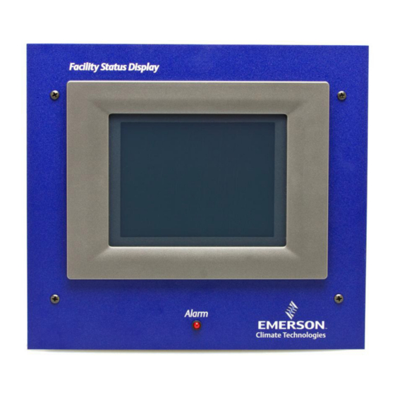
• Display of up to 150 customizable data points. Figure 1-1 - Facility Status Display The FSD has a touch screen color display for quick navigation and can be mounted in a separate, remote location from the E2 controller, which enables alarms and other relevant store information to be viewed from where it is most convenient for the user. -
Page 8: Installation
1. Step 1: Using the four screws on the front of the mounting plate, unscrew the cover of the FSD Circuit Transformer FSD and remove, exposing the back of the Board enclosure. Once the top has been separated Inside Back of Enclosure... -
Page 9: Alarm Relays
This output allows an external alarm indicator to be installed away from the board. 2.3. Mounting The FSD is recess-mounted into a wall or other mounting surface. The face plate with the LCD dis- play (front portion of the unit) will mount flush... - Page 10 Push-out Open Side of Tabs Power Supply Box 8.0” 9.0” Mount Back Portion of FSD Power Supply Box Inside Wall Figure 2-4 - Mounting The Power Supply Box leave ½” clearance each side for face plate 1/2” Open Side of 8.0”...
-
Page 11: Set Up Fsd And E2 Communication • 5
Because the FSD device retrieves all software in- formation from the E2 controller, communication must be established between the FSD and the E2 at start-up. To start, add the FSD application to the E2. 3.1. STEP 1: Add FSD to E2 1. -
Page 12: Step 3: Set The E2 Ip Address In Fsd
3. Touch Apply. Address in FSD 4. Reboot the unit by cycling power. To set up the FSD, the E2’s IP address or Host- name that the FSD will communicate with must be en- tered. When the FSD is powered up for the first time, the Start-up or Boot Loader screens will appear. -
Page 13: Alarm Overview
(alarm or Snooze) will be canceled automatically. The FSD contains an audible alarm that can be en- Automatic color-coding allows for simple differ- abled or disabled by the installer or service technician entiation between those advisories that are urgent and and is pass-code protected. -
Page 14: Fsd Screen Navigation
The Home screen also displays wheth- tiple alarms on the Home screen. er the FSD is communicating with the E2 or if com- munication with the E2 has been interrupted or DOWN arrow scrolls downward stopped. -
Page 15: Advisory Detail Screen
Figure 5-3 - Advisory Detail Screen (Figure 6-1). • Current alarm number with the total number of See Section 6, E2 Data Point Setup for FSD to alarms in the alarm list configure these parameters for the FSD Data Point •... -
Page 16: Data Points Detail Screen
(- - -) value is selected and the details icon touched, the following message will appear: Figure 5-6 - Detailed Information if the Data Point Failed Figure 5-9 - No Pointer Is Defined Message 10 • FSD Installation and Operation Manual 026-1400 Rev 3 22-MAR-2011... -
Page 17: Fsd Configuration Screen
(RTN). For example, if a case goes into alarm, the screen. FSD will see the alarm; however, if the alarm returns to normal, the alarm will not be visible on the FSD, al- though it is seen in the individual controller’s alarm log as Return-To-Normal. Enable the checkbox to show returned-to-normal alarms, uncheck to filter out. -
Page 18: Show Reset Advisories
This alarm setting enables you to display or hide Refer to Figure 5-13 for a sample illustration. reset alarms on the FSD. Reset alarms are alarms that have been forced to normal condition or “Reset-to- Normal.” Enable the checkbox to show reset alarms or uncheck to filter out. -
Page 19: Snooze Delay
5.4.2.2. E2 IP Port alarm indicator. • None disables all audible alarm indicators. The E2 IP Port is the port number used by the FSD to connect with the E2 unit. The port number in this 5.4.1.8. Snooze Delay field must match the FSD Client Port field in the E2 for the FSD and the E2 to communicate. -
Page 20: About Tab
Properties. Figure 5-16 - FSD About Tab 5.4.5. Backlight Time-out Setting To increase the life of the display, the FSD’s back- light time-out setting is pre-configured to turn off the backlight automatically if the device is idle for more than 10 minutes. - Page 21 6. To save your settings, touch and drag the Display Properties window to the left until you see OK in the upper right corner. Touch OK to save and return to the desktop screen. FSD Configuration Screen FSD Screen Navigation • 15...
-
Page 22: E2 Data Point Setup For Fsd
If the Title Data Point parameters are not changed, Names (Pts Names) setup. the FSD Data Points screen will use the default values set for these parameters (i.e., the Global Data’s OAT). 6. Press F2 Next Tab to go the Data Pts setup and enter the desired data points to be moni- tored by pressing F4: Look Up. - Page 23 (- - -) on the Facility Status Display screen. 8. Go to the Pts Names tab and enter a name for the data point (Figure 6-4). FSD Configuration Screen E2 Data Point Setup for FSD • 17...
-
Page 24: E2 Ethernet Peer Communications
• The maximum number of controllers allowed on an IP subnet is 20. All E2 controllers that must communicate with each other must be on the same subnet. • Recommended Ethernet cabling is CAT 5 18 • FSD Installation and Operation Manual 026-1400 Rev 3 22-MAR-2011... -
Page 25: Software Specifications
7.3. Software NOTE: The gateway E2 is the E2 controller at Specifications a remote site to which UltraSite directly con- nects. It is through this E2 that UltraSite com- municates with the other controllers (defined TCP/IP as the “non-gateway” E2s and external entities such as UltraSite, InSite, Site Manager, etc.). -
Page 26: Software Setup
(Section 7, E2 Ethernet Peer Communi- cations). Consult your IT Network Administrator for any additional information needed. Figure 7-4 - Peer Network Tab - Set Network Type 20 • FSD Installation and Operation Manual 026-1400 Rev 3 22-MAR-2011... -
Page 27: E2 Alarm Annunciator Setup
If more than one E2 is at a site, set up one E2 as the from the configured E2. alarm annunciator. The FSD will receive alarms from that alarm-annunciator E2 for the entire site. Any E2 on the network that has a modem or Ether-... -
Page 28: Specifications
-4 to 140°F (-20 to 60°C) Dimensions Screen (diagonal): 3.5” / Flush mounting plate: 9” x 10” / Mounting hole: 9” x 8” Table 10-1 - Facility Status Display Specifications 22 • FSD Installation and Operation Manual 026-1400 Rev 3 22-MAR-2011...
Need help?
Do you have a question about the FSD and is the answer not in the manual?
Questions and answers