Teledyne SeaBat T Series Operator's Manual
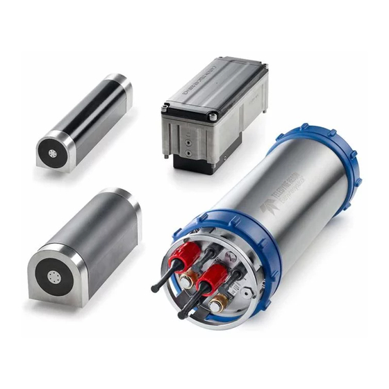
Deep/shallow high-resolution multibeam sonar system
Hide thumbs
Also See for SeaBat T Series:
- Quick reference manual (4 pages) ,
- Quick reference manual (4 pages)


Need help?
Do you have a question about the SeaBat T Series and is the answer not in the manual?
Questions and answers