Sign In
Upload
Download
Table of Contents
Contents
Add to my manuals
Delete from my manuals
Share
URL of this page:
HTML Link:
Bookmark this page
Add
Manual will be automatically added to "My Manuals"
Print this page
×
Bookmark added
×
Added to my manuals
Manuals
Brands
Teledyne Manuals
Sonar
SeaBat T50-S
Operator's manual
Teledyne SeaBat T50-S Operator's Manual
Deep/shallow high-resolution multibeam sonar system
Hide thumbs
1
2
3
4
5
6
Table Of Contents
7
8
9
10
11
12
13
14
15
16
17
18
19
20
21
22
23
24
25
26
27
28
29
30
31
32
33
34
35
36
37
38
39
40
41
42
43
44
45
46
47
48
49
50
51
52
53
54
55
56
57
58
59
60
61
62
63
64
65
66
67
68
69
70
71
72
73
74
75
76
77
78
79
80
81
82
83
84
85
86
87
88
89
90
91
92
93
94
95
96
97
98
99
100
101
102
103
104
105
106
107
108
109
110
111
112
113
114
115
116
117
118
119
120
121
122
123
124
125
126
127
128
129
130
131
132
133
134
135
136
137
138
139
140
141
142
143
144
145
146
147
148
149
150
151
152
page
of
152
Go
/
152
Contents
Table of Contents
Troubleshooting
Bookmarks
Table of Contents
Table of Contents
Introduction
System Overview
System Architecture
System Operation
Figure 1: Seabat T-Series Subsea System Configuration
System Features
Table 1: Seabat T-Series Subsea Feature Pack
Typical Applications
Available Seabat T-Series Subsea Configurations
Table 2: Seabat T-Series Subsea Available Configurations
Safety Precautions
Operator Safety
Equipment Safety
Safe Handling
Cleaning and Maintenance
Corrosion Avoidance
Electrical Isolation
Exposure to Sunlight
Safe Disposal of Waste (WEEE Directive)
System Startup and Shutdown
Chapter Overview
Pre-Dive Checks
System Startup Instructions
AUV System
ROV System
System Shutdown Instructions
AUV System
ROV System
Post-Dive Checks
System Configuration with User Interface
Chapter Overview
Sonar User Interface (SUI)
Remote Operation
Remote Desktop Session
Folder Management
File Sharing on a Network
Verifying or Changing the Computer Name And/Or Workgroup Name
UUV System Operation
Chapter Overview
AUV System Operation
ROV System Operation
Active Sonar Usage
Chapter Overview
Enhancing Sonar Performance
Correct Range Setting
Figure 2: Range Setting Diagrams
Figure 3: Range Setting - too Long
Table 3: Incorrect Range Settings - Examples and Solutions
Transmit Power
Figure 4: Range Setting - too Short
Figure 5: Range Setting - the Exception
Ping Rate
Receiver Gain
Frequency Selection
Pulse Length
Table 4: TVG Formula
Pulse Type
Vari-Swath
Figure 6: Example of Reduced Swath Width
Figure 7: Horizontal Swath Steering
Use of Beam Modes
Figure 8: Outer Beams for the Different Beam Modes with a Tilted Sonar Head
Use of Gates
Figure 9: Graphic Illustration of Flexmode
Figure 10: Depth Gates, with no Roll
Figure 11: Depth Gates, with Roll
Figure 12: Depth Gates, with Roll and Motion Sensor Input
Enhancing System Efficiency
Multi-Detect Operation
Figure 13: Depth Gate Tilt
Figure 14: Submerged Oil Detected by Multi-Detect
Tracker Autopilot
Roll Stabilization
Figure 15: Swath under Zero Roll Conditions
Head Tilt
Figure 16: Laterally Displaced Swaths under Roll Conditions
Figure 17: Swath under Roll Stabilization
Compensation for Environmental Conditions
Figure 18: Head Tilt Functionality
Figure 19: Head Tilt for Harbor Inspection
Figure 20: Head Tilt for Pipe Inspection
Loss of Sound by Absorption
Figure 21: Acoustic Absorption Reference
Loss of Sound by Spreading
Sound Velocity
Figure 22: Typical Sound Velocity Values
Limitations
Cavitation
Machinery Noise
Interference from Other Sonar Systems
Speed
Air Bubbles
Environment
System Performance and Data Types
Table 5: Seabat T-Series Subsea System Performance
System Components
Subsea Sonar Processor
Figure 23: Subsea Sonar Processor
EM7219-1 Receiver Unit (T20)
EM7218-1 Receiver Unit (T50)
TC2160 Projector Unit (Deep)
Figure 24: EM7219 Receiver Unit
Figure 25: EM7218 Receiver Unit
Figure 26: TC2160 Projector Unit
TC2163 Projector Unit (Deep)
TC2181 Projector Unit (Shallow)
Figure 27: TC2163 Projector Unit
Figure 28: TC2181 Projector Unit
Selectable Beam Density
Beam Modes
Table 6: Beam Modes with No. of Beams and Swath Coverage
Equi-Distant, Equi-Angle, and Intermediate Modes
Figure 29: Beam Density
Figure 30: Beam Spacing Vs. Beam Angle
Figure 31: Beam Spacing
Figure 32: Across-Track Sounding Location on a Flat Bottom
Data Types
Bathymetry Data
Side-Scan Data
Snippets Backscatter Data
Figure 33: Graphic Illustration of Snippets Data
Multi-Detect
X-Range Performance
Full Rate Dual Head
Figure 34: Standard Detection
Figure 35: Multi-Detect with Enhanced Detail on Quay Wall
Figure 36: Multi-Detect
Quality
Brightness Test
Figure 37: Dual Head Synchronization of Pings
Colinearity Test
Figure 38: Brightness Test
Figure 39: Colinearity Flags
Quality Filter
Uncertainty Estimation
Hydrodynamic Drag
Drag Simulation Setup
Drag Simulation Conclusions
Drag Simulation Results
Figure 40: T20 Sonar Head (Shallow) in Bracket with Optional Front Fairing
Figure 41: Flow at 10 Knots Around Single T20 (Shallow) with Fairing
Figure 42: Flow Around Single T20 (Shallow) with Fairing, Cross Section of Symmetry Plane
Figure 43: Flow at 10 Knots Around Single T20 (Shallow) Without Fairing
Figure 44: Flow Around Single T20 (Shallow) Without Fairing, Cross Section of Symmetry Plane
Figure 45: T20 Dual Sonar Head Assembly in Bracket with Optional Front Fairing
Figure 46: Flow at 10 Knots Around Dual T20 with Fairings
Figure 47: Flow Around Dual T20 with Fairings, Cross Section of Symmetry Plane
Figure 48: Flow at 10 Knots Around Dual T20 Without Fairings
Figure 49: Flow Around Dual T20 Without Fairings, Cross Section of Symmetry Plane
Figure 50: T50 Sonar Head (Shallow) in Bracket with Optional Front Fairing
Figure 51: Flow at 10 Knots Around Single T50 (Shallow) with Fairing
Figure 52: Flow Around Single T50 (Shallow) with Fairing, Cross Section of Symmetry Plane
Figure 53: Flow at 10 Knots Around Single T50 (Shallow) Without Fairing
Figure 54: Flow Around Single T50 (Shallow) Without Fairing, Cross Section of Symmetry Plane
Figure 55: T50 Dual Sonar Head Assembly in Bracket with Optional Front Fairing
Figure 56: Flow at 10 Knots Around Dual T50 with Fairings
Figure 57: Flow Around Dual T50 with Fairings, Cross Section of Symmetry Plane
Figure 58: Flow at 10 Knots Around Dual T50 Without Fairings
Figure 59: Flow Around Dual T50 Without Fairings, Cross Section of Symmetry Plane
Ping Rate Table
Table 7: Ping Rate Table
Appendix A Troubleshooting
System Error and Warning Messages
Error Messages
General System Startup Errors
PCI Card Related (ADMXRC) Errors
Data Reading Errors
System Resource Errors
Input Signal (Timing and Triggers) Errors
Calibration Errors
Warning Messages
Configuration Warnings
Startup Warnings
Data Processing Warnings
Data Recording Warnings
BITE Data Warnings
Input Signal Warnings
System Stability Warnings
Data Subscription Warnings
Network Components Warnings
External Trigger Warnings
Error Messages - Master List in Alphabetical Order
Warning Messages - Master List in Alphabetical Order
Appendix B Installation Instructions
Components Checklist
Table 8: Seabat T-Series Subsea Components
Installation Checklist
System Interfacing
AUV Installation
ROV Installation
Figure 60: AUV Configuration
Figure 61: Typical ROV Installation
Interfacing Diagrams
Figure 62: Bulkhead Cable Connections
Figure 63: T20/50-S AUV, Single/Dual-Head Interfacing Diagram
Figure 64: T20/50-S ROV, Single/Dual-Head Interfacing Diagram
Seabat T-Series Subsea Cables
Seabat T-Series Subsea Transducer Cables
Seabat T-Series Subsea External Sensor Cable
UUV Interface Cable
Pin Designations for Host, AUX, LAN2, and SVP Connectors
Table 9: Pin Designations for Host Connector (TIA/EIA 568B)
Table 10: Pin Designations for AUX Connector
Table 11: Pin Designations for LAN2 Connector (TIA/EIA 568B)
Table 12: Pin Designations for SVP Connector
Table 13: TIA/EIA 568B Overview
Seabat T-Series Subsea Installation
Subsea Sonar Processor (PN 1009483)
EM7219-1 Receiver Unit (PN 85002536) - T20
Table 14: SSP Technical Specifications
Table 15: EM7219-1 Receiver Unit Technical Specifications
EM7218-1 Receiver Unit (PN 85002538) - T50
TC2160 Projector Unit (Deep Operation) (PN 85000328)
Table 16: EM7218-1 Receiver Unit Technical Specifications
Table 17: TC2160 Projector Unit Technical Specifications
TC2163 Projector Unit (Deep Operation, Optional) (PN 85000327)
TC2181 Projector Unit (Shallow Operation) (PN 85002319)
Table 18: TC 2163 Projector Unit Technical Specifications
Table 19: TC2181 Projector Unit Technical Specifications
Wet-End Cable Connections
Figure 65: SSP Pressure Bottle Connections
Sonar Head Assembly Orientation
Sonar Reference Point
Wet-End Mounting
Hardware Settings
System Check
Appendix Cnetwork Configuration
Single-Head System Network Configuration
Change IP Configuration
Table 20: IP Configuration for SSP
Appendix Dpps in and Trigger in
Electrical Specifications for PPS in and Trigger in
Typical PPS in and Trigger Performance
Figure 66: Required PPS Pulse Width
Table 21: PPS in and Trigger in Signals
Hints and Advice
Figure 67: PPS in Delay
Figure 68: Pps/Trigger Signal
Appendix E Reference Documentation
Seabat T-Series Subsea Documentation
Figure 69: System Documentation Link (Example Only)
Seabat T-Series Subsea Design Documents
Figure 70: Receiver, EM7219-1 Outline Dimensions
Figure 71: Receiver, EM7218 Outline Dimensions
Figure 72: Projector, TC2160 Outline Dimensions (for Deep Installation)
Figure 73: Projector, TC2163 Outline Dimensions (for Deep Installation)
Figure 74: Projector, TC2181 Outline Dimensions (for Shallow Installation)
Figure 75: Subsea Sonar Processor, Outline Dimensions
Figure 76: Cable Assembly, Receiver to SSP and Host Cable
Figure 77: Cable Assembly, TC 2163/60 Projector to SSP (Deep)
Figure 78: Cable Assembly, TC2181 Projector to SSP (Shallow)
Figure 79: Cable Assembly, Bulkhead Connector for ROV
Figure 80: Cable Assembly, AUX Pigtail
Figure 81: Cable Assembly, SSP to SVP 70 (Optional)
Figure 82: Sonar Reference Point Definition
7Kcenter Licenses - Copyright Information
Table 22: LAPACK - Copyright Information
Table 23: Winpcap - Copyright Information
Appendix Fseabat T-Series Subsea System Options
Extended Warranty Contract
Fiber-Optic Converter (for ROV Installations)
Figure 83: TC3300 Media Converter (Single-Mode Fiber Version)
Table 24: TC3300 Fiber-Optic Converter Technical Specifications
Seabat Cables
Service Level Agreement
Sound Velocity Probe
Table 25: SVP Technical Specifications
System Integration and Training
Teledyne PDS Data Acquisition Software
Wet-End Brackets (Customized)
Appendix Gwarranty Information
Three-Year Limited Warranty
Exclusions
Warranty Limitations
Servicing During Warranty Period
Equipment Return Procedure
Service
Seabat T-Series Subsea Operator's Manual
Advertisement
Quick Links
1
Figure 1: Seabat T-Series Subsea System Configuration
Download this manual
SeaBat T-Series Subsea
T20/50-S Deep/Shallow High-Resolution
Multibeam Sonar System
OPERATOR'S MANUAL
Part Number 1009737
Version 7
January 2019
Table of
Contents
Previous
Page
Next
Page
1
2
3
4
5
Advertisement
Table of Contents
Need help?
Do you have a question about the SeaBat T50-S and is the answer not in the manual?
Ask a question
Questions and answers
Related Manuals for Teledyne SeaBat T50-S
Sonar Teledyne SeaBat T20-S Operator's Manual
Deep/shallow high-resolution multibeam sonar system (152 pages)
Sonar Teledyne SeaBat T-Series Operator's Manual
High-resolution multibeam sonar system (190 pages)
Sonar Teledyne SeaBat T Series Operator's Manual
Deep/shallow high-resolution multibeam sonar system (152 pages)
Sonar Teledyne BlueView M Series Quick Start Manual
(2 pages)
Sonar Teledyne P series User Manual
(28 pages)
Sonar Teledyne Sonar UI SeaBat T Series Quick Installation Manual
(2 pages)
Sonar Teledyne UI User Manual
Seabat sonar (128 pages)
Sonar Teledyne BV3200 User Manual
Pole mount (25 pages)
Sonar Teledyne BlueView BV3200 Quick Start Manual
(2 pages)
Sonar Teledyne P-Series Quick Start Manual
Sonar with vdsl (4 pages)
Summarization of Contents
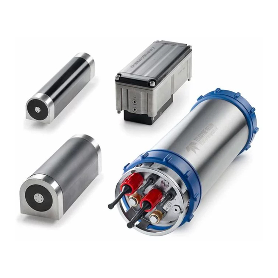
1 Introduction to SeaBat T-Series Subsea
1.1 System Overview
Provides a general overview of the SeaBat T-Series Subsea sonar system and its configurations.
1.2 System Architecture
Details the components and connections of the SeaBat T-Series Subsea sonar system.
1.3 System Operation
Explains how the SeaBat T-Series Subsea sonar system transmits, receives, and processes acoustic energy.
1.4 System Features
Details the various features and capabilities of the SeaBat T-Series Subsea sonar system.
1.5 Typical Applications
Lists the wide range of applications supported by the SeaBat T-Series Subsea system.
1.6 Available Configurations
Presents the different hardware configurations available for the SeaBat T-Series Subsea system.
2 Safety Precautions for SeaBat Systems
2.1 Operator Safety
General precautions for safe handling and operation of the SeaBat T-Series Subsea system.
2.2 Equipment Safety
Guidelines for protecting SeaBat T-Series Subsea system components during handling and storage.
3 System Startup and Shutdown Procedures
3.1 Chapter Overview
Outlines the topics covered in the System Startup and Shutdown chapter.
3.2 Pre-dive Checks
Lists essential checks to perform before deploying the SeaBat T-Series Subsea system.
3.3 System Startup Instructions
Provides step-by-step instructions for starting up the SeaBat T-Series Subsea system for AUV and ROV.
3.4 System Shutdown Instructions
Details procedures for safely shutting down the SeaBat T-Series Subsea system for AUV and ROV.
3.5 Post-dive Checks
Outlines checks to perform after recovering the SeaBat T-Series Subsea system from water.
4 System Configuration with User Interface
4.1 Chapter Overview
Introduces the chapter on system configuration and user interface operations for SeaBat systems.
4.2 Sonar User Interface (SUI)
Instructions for starting and using the Sonar User Interface for system configuration.
4.3 Remote Operation
Explains how to control the SeaBat sonar system remotely using the 7k Center architecture.
4.4 Remote Desktop Session
Steps for establishing a remote desktop session to access the SeaBat SSP.
4.5 Folder Management
Describes how to manage folders, including sharing and renaming, on the SeaBat SSP.
5 UUV System Operation
5.1 Chapter Overview
Introduces the chapter covering UUV system operation for SeaBat systems.
5.2 AUV System Operation
Details the normal mission sequence and operation of the SeaBat system in AUV mode.
5.3 ROV System Operation
Provides notes on ROV system operation for SeaBat sonar systems.
6 Active Sonar Usage
6.1 Chapter Overview
Introduces the chapter on practical sonar usage, performance enhancement, and environmental factors.
6.2 Enhancing Sonar Performance
Guidance on optimizing sonar performance through settings like range, power, and frequency.
6.3 Enhancing System Efficiency
Techniques to improve system efficiency, including multi-detect, tracker, and roll stabilization.
6.4 Compensation for Environmental Conditions
How environmental factors like absorption and spreading affect sonar performance.
6.5 Limitations
Discusses physical limitations of the SeaBat system, such as cavitation and noise.
7 System Performance and Data Types
7.1 System Components
Details the core components of the SeaBat T-Series Subsea sonar system, including the SSP and receivers.
7.2 Selectable Beam Density
Allows selection of beam density to optimize data volume and processing efficiency.
7.3 Data Types
Describes the types of data generated by the SeaBat system: bathymetry, side-scan, snippets.
7.4 Multi-Detect
Feature providing multiple detections within each beam for enhanced detail and water column data.
7.5 X-Range Performance
Feature for extended range and improved immunity to external noise.
7.6 Full Rate Dual Head
Superior dual head implementation offering simultaneous pinging for increased range and rate.
7.7 Quality
Evaluation of bathymetric bottom detection quality using tests like Brightness and Colinearity.
7.8 Uncertainty Estimation
Calculation and display of Total Propagated Uncertainty (TPU) for sounding quality assessment.
7.9 Hydrodynamic Drag
Analysis of hydrodynamic drag on sonar head assemblies under various conditions.
Appendix A Troubleshooting SeaBat Systems
A.1 System Error and Warning Messages
Lists error and warning messages generated by the 7k Center software for troubleshooting.
A.2 Error Messages
Detailed list of error messages, their descriptions, and recommended actions for resolution.
A.3 Warning Messages
Lists warning messages generated by the 7k Center software with descriptions and actions.
Appendix B Installation Instructions
B.1 Components Checklist
Lists standard components included in a SeaBat T-Series Subsea delivery.
B.2 Installation Checklist
Basic steps for installing and configuring a new SeaBat sonar system.
B.3 System Interfacing
Diagrams and instructions for interfacing the SeaBat system with AUV and ROV configurations.
B.4 SeaBat Cables
Describes SeaBat T-Series Subsea transducer, external sensor, and UUV interface cables.
B.5 SeaBat Installation Details
Technical specifications and installation details for SeaBat system components.
B.6 System Check
Steps to verify the SeaBat T-Series Subsea system is working correctly after installation.
Appendix C Network Configuration
C.1 Single-Head Network Configuration
Default network configuration for the SeaBat T-Series Subsea SSP.
C.2 Change IP Configuration
Instructions for changing the IP configuration of the SeaBat SSP via the Sonar UI.
Appendix D PPS In and Trigger In
D.1 Electrical Specifications
Electrical specifications for PPS In and Trigger In signals used with the SeaBat system.
D.2 Typical Performance
Graphical representation of typical PPS In and Trigger performance characteristics.
D.3 Hints and Advice
Practical advice and considerations for using PPS and trigger inputs with the SeaBat system.
Appendix E Reference Documentation
E.1 SeaBat Subsea Documentation
Lists available SeaBat T-Series Subsea documentation in Adobe Portable Document Format.
E.2 Design Documents
Lists design documents and drawings available for reference purposes.
E.3 7kCenter Licenses
Copyright information related to the 7kCenter software used with the SeaBat system.
Appendix F SeaBat System Options
F.1 Extended Warranty Contract
Information on purchasing additional annual support for SeaBat T-Series Subsea systems.
F.2 Fiber-Optic Converter
Details on the fiber-optic converter option for long cable runs in ROV installations.
F.3 SeaBat Cables
Information on the availability of additional SeaBat cables in various lengths.
F.4 Service Level Agreement
Overview of services covered under the SeaBat Service Level Agreement.
F.5 Sound Velocity Probe
Technical specifications for the Sound Velocity Probe (SVP) used with the SeaBat system.
F.6 System Integration and Training
Services available for onsite system integration, calibration, and operator training.
F.7 Teledyne PDS Software
Information on Teledyne PDS software for data acquisition and processing.
F.8 Wet-End Brackets
Availability of customized wet-end brackets for SeaBat systems.
Appendix G Warranty Information
G.1 Three-Year Limited Warranty
Details the terms of the three-year limited warranty for Teledyne RESON systems.
G.2 Exclusions
Lists conditions and circumstances under which the warranty does not apply.
G.3 Warranty Limitations
States the warranty is exclusive and disclaims implied warranties of merchantability and fitness.
G.4 Servicing During Warranty Period
Guidance on contacting Teledyne RESON representatives for service during the warranty period.
G.5 Equipment Return Procedure
Steps to follow for returning equipment for service, including obtaining an RMA number.
G.6 Service Contacts
Contact information for Teledyne RESON service departments in different regions.
Table of Contents
Save PDF
Print
Rename the bookmark
Delete bookmark?
Delete from my manuals?
Login
Sign In
OR
Sign in with Facebook
Sign in with Google
Upload manual
Upload from disk
Upload from URL
Need help?
Do you have a question about the SeaBat T50-S and is the answer not in the manual?
Questions and answers