
Related Manuals for Teledyne BV3200


Summary of Contents for Teledyne BV3200
- Page 1 User’s Manual BV3200 Pole Mount Part Number: 204765-00 Revision: A, October 2014 © 2014 Teledyne BlueView Technologies, Inc. All rights reserved. All product names are trademarks of their respective companies. Page | 0...
-
Page 2: Table Of Contents
Installing the Junction Box .................... 9 Final Cable Connections .................... 11 Install ProViewer 4 Software ..................11 Configure PC ......................12 Connecting the BV3200 GPS in ProViewer 4 ..............12 Sonar Angle ......................15 ProMapper Add-On Software ..................16 GPS Heading/Compass Calibration ................16 System Breakdown .................... -
Page 3: Part Number
Warranty Information: The BV3200 is backed by a standard 12-month parts and labor warranty policy. Seller’s terms and conditions of sale can be found at www.blueview.com For more information on safety and/or maintenance issues please call Teledyne BlueView, Inc. -
Page 4: Chapter 1: Important Safeguards
If the box does fall in the water, unplug before retrieving. WARNING – To reduce the risk of burns, electrocution, fire, or injury to persons: 1. Use this BV3200 and sonar only for its intended use as described in this manual. Do not use attachments not recommended by BlueView Technologies. -
Page 5: Chapter 2: System Components
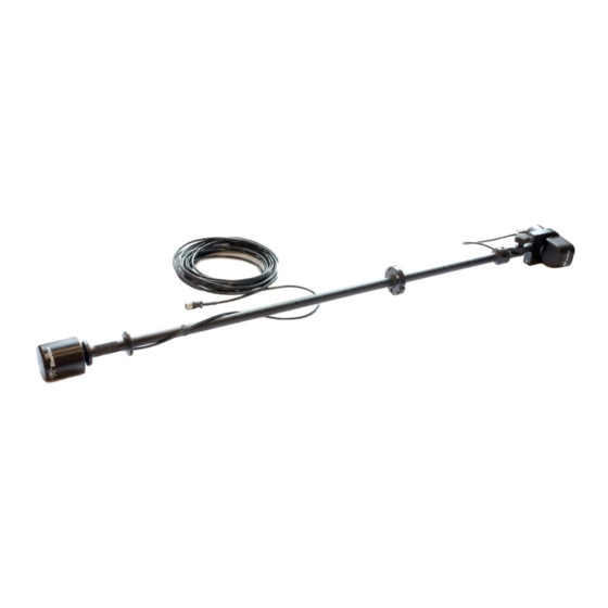
BV3200 Transport Case Pole Assembly Junction Box Pole Mount 7 Ft Ethernet Cable USB Cable Power Cable BV3200 Software and Manuals CD Containing: BV3200 QuickStart Guide BV3200 User’s Manual ProViewer 4 Software ProViewer 4 Handbook USB Serial Adapter Driver Software Hex Driver... -
Page 6: System Overview
Junction Box, which then connects to a PC via USB and Ethernet. The BV3200 system is airline checkable luggage. To familiarize yourself with the BV3200 system, please review the information in this manual. BV3200 unit in travel case... -
Page 7: Chapter 3: Setup & Operation
The following instructions will walk you through all steps necessary to assemble the pole, mount the sonar, and connect all required cabling. 1. Remove the BV3200 pole unit from case. 2. Place the top and bottom pole pieces end to end. Pull the sonar cable through the pole as you bring the pole bolt flanges together. - Page 8 4. Attach the lower section to the upper using the provided cap screws. Insert the bolt first through the unthreaded upper flange and screw into the threaded lower flange. Attach the sonar to the sonar clamp by loosening the four cap screws, sliding in the sonar and retightening the four cap screws.
-
Page 9: Tilt Angle Adjustment
Tilt Angle Adjustment It is the user’s responsibility to insure the pole mount is secured in a way that will NOTE: support the pole assembly. 1. Loosen the clamp angle adjustment knob by turning the knob counterclockwise. 2. Lift the clamp until the angle adjustment selector clears the angle keyway. 3. -
Page 10: Junction Box
Junction Box The Junction Box contains a power supply and a USB to RS-485 Converter. The power supply provides power to both the GPS unit and sonar. The converter adds a COM port to the PC so the PC can receive GPS data via a USB port. -
Page 11: Installing The Junction Box
COM port to the PC for communicating with the pan and tilt. The drivers for the converter need to be installed onto the PC. These drivers are located on the provided CD labeled “BV3200 CD” in the “Junction Box” folder under “Drivers.”... - Page 12 Driver Software.” You will be asked how you want to search for driver software. Select “Browse my computer for driver software.” 5. Browse to the “BV3200 CD.” “J-Box.” “Drivers,” and select “OK.” Click “Next” and follow screen prompts to complete driver installation.
-
Page 13: Final Cable Connections
Final Cable Connections 1. Connect the sonar and GPS cables to the Junction Box. Connect the Ethernet cable to the control box, then to an available network connection port on the PC. Verify that all connections in the diagram below have been made. 2. -
Page 14: Configure Pc
Note: Running other applications in conjunction with the ProViewer Software may affect performance of one or both of the applications. Place the BV3200 CD in the CD-ROM drive and open the “ProViewer 4” folder. Double-click the “setup” icon to begin installation. - Page 15 COM Port Settings: Select the proper COM port value corresponding to the GPS device USB connection. Select a baud rate of 4800, data bits of 8, no parity, one stop bit, and no flow control. NMEA Sequences: The BV-3200 is setup to receive only select NMEA sequences. Under NMEA Sequences select: HDT, RMC, and ZDA.
- Page 16 Start All: Click this button to begin displaying NMEA information on your ProViewer main window. LAT, LONG and Heading will be displayed in the lower right hand corner of your ProViewer 4 window. Stop All: Click this button to stop displaying NMEA information on your ProViewer main window. Page | 14...
-
Page 17: Sonar Angle
Sonar Angle To achieve optimal performance while imaging targets and/or the bottom at a given depth, the angle that the sonar is tilted down from the surface is important. This issue is demonstrated in the figures below. On the left, the sonar is tilted down at a steep angle that provides only a narrow field of view of the bottom. The sonar on the right-hand figure is set at a much shallower angle that provides both a better perspective on targets and a larger field-of-view of the bottom. -
Page 18: Promapper Add-On Software
Auto Calibration Procedure 1. Install the BV3200 on the vessel with the arrow on the top of the unit pointing parallel to the boat centerline, and in the direction of forward travel. 2. In calm seas, navigate the vessel to an open area of water, 0.8 km (0.5 mile) of open space away from other boats or ferrous objects (structures or aids to navigation). -
Page 19: System Breakdown
System Breakdown Proper system breakdown of the BV3200 requires only that the AC power and pole cable be disconnected from the console, rinse the pole and sonar with fresh water and return to their respective positions in the carrying case, as shown. -
Page 20: Chapter 4: Maintenance
3. Inspect all cables and connectors for abrasion, cuts or cracks. Repair or replace as needed. After Use 1. After use rinse all BV3200 components with a solution of mild soap and fresh water. At this time, inspect all components for corrosion, wear or damage. Replace any piece of hardware showing corrosion or damage. -
Page 21: Chapter 5: Troubleshooting
Chapter 5: Troubleshooting Symptoms Possible Cause Resolution The sonar software does Junction Box AC power Cord is not Ensure the console power cord is not automatically find the plugged into active AC outlet plugged into an active AC outlet connected sonar. Sonar not connected Verify the main pole cable is plugged into the Junction Box. -
Page 22: Still Not Working
Still not working? Please contact us: BlueView Technologies Customer Support www.blueview.com +1.425.492.7376 8am – 5pm PST Mon through Fri swa_support@teledyne.com Page | 20... -
Page 23: Appendix A: Technical Specifications
Appendix A: Technical Specifications GPS Position Accuracy 10 ft. (3m) Position Resolution 1° Static Compass Accuracy 1° RMS when level Dynamic Compass Accuracy 2° Heading Display Resolution 0.1° Rate-of-Turn Accuracy 1° per second GPS-Fix Update Rate 2 x per second Pole Mount Pole Length (Extended) 77.5 in... -
Page 24: Appendix B: Connector Pinouts
Appendix B: Connector Pinouts Sonar + Junction Box 8 Pin Connector to Sonar and GPS Unit (Souriau UTG012-8S) Function Ethernet RX+ (to sonar) Ethernet RX- (to sonar) Ethernet TX- (to sonar) +24V DC Ground Ethernet TX+ (to sonar) RS485A RS485B 3 Pin C14 Power Connector Function 110-240V AC... - Page 25 Sonar Cable Ends 10 Pin Connector to Sonar (Impulse MKS-310-CCP- Function Ethernet RX+ (to sonar) Ethernet RX- (to sonar) Ethernet TX+ (to sonar) +24V DC +24V DC Ethernet TX- (to sonar) Ground Ground 8 Pin Connector to Sonar (Burton 55R1-1508 ) Function Ethernet RX+ (to sonar) Ethernet RX- (to sonar)
Need help?
Do you have a question about the BV3200 and is the answer not in the manual?
Questions and answers