
Subscribe to Our Youtube Channel
Related Manuals for Teledyne P series


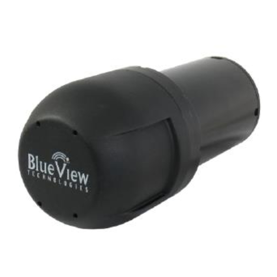
Summary of Contents for Teledyne P series
- Page 1 Part Number: 202914-00 Revision: I January 2016 ©2016 Teledyne BlueView, All rights reserved. All product names are trademarks of their respective companies.
- Page 2 Description Power-Over-Ethernet (POE) Box Sonar to Surface Cable (25 ft.) Cable Whip (4 ft.) Ethernet Cable (7 ft.) ProViewer CD Quickstart Guide User Handbook Rugged Carry Case Page 2 of 28 ©...
- Page 3 ......................2 ......................6 ................. 6 ................7 ..................... 7 ................7 ....................8 ..................... 8 ......................8 ......................9 ......................9 ..................10 ..................... 11 ......................11 ..................12 ............... 12 ................12 ..................14 .................... 15 ....................... 15 ....................
- Page 4 ..................21 ...................... 21 .................. 22 ..................24 .................... 24 ..................25 ..................25 ............... 26 .................... 27 Page 4 of 28 ©...
- Page 5 Page 5 of 28 ©...
- Page 6 Page 6 of 28 ©...
- Page 7 Page 7 of 28 ©...
- Page 8 Page 8 of 28 ©...
- Page 9 Page 9 of 28 ©...
- Page 10 Connect Page 10 of 28 ©...
- Page 11 Page 11 of 28 ©...
- Page 12 Page 12 of 28 ©...
- Page 13 RJ11 Connector To the Sonar Power Cable Plug VDSL link to sonar PC link Power Page 13 of 28 ©...
- Page 14 Connect Page 14 of 28 ©...
- Page 15 Bottom Bottom Page 15 of 28 ©...
- Page 16 Target Depth (ft) Approx. Tilt Angle(Deg) Page 16 of 28 ©...
- Page 17 Page 17 of 28 ©...
- Page 18 Page 18 of 28 ©...
- Page 19 Page 19 of 28 ©...
- Page 20 Confirm that the POE Box is plugged into a standard 120 or 220 VAC outlet and No Power that the small green LED on the POE Box is illuminated. Check that the Sonar- to-Surface cable is plugged into the SONAR J1 port on the POE Box. In addition to the connections described above, verify that you have a good Improperly connected cable between the computer Ethernet port and the PC J2 port on the POE Box.
- Page 21 Shut down any other computers or services that are consuming the Ethernet Ethernet congestion network bandwidth When your sonar pings, it must wait for the echo to return from a distant Range settings object; long range settings directly cause slow updates. Reduce the Range Stop distance to increase the update rate.
- Page 22 P450-45 P450-90 P450-130 P900-45 P900-90 P900-130 P900/2250-45 Sonar Field-of- 45º 90º 130º 45º 90º 130º 45º View 100m (328 ft.) @ 900kHz 300m 300m 300m 100m 100m 100m Max. Range 8m (26.2 ft.) @ (984 ft.) (984 ft.) (984 ft.) (328 ft.) (328 ft.) (328 ft.)
- Page 23 P450-45 P450-90 P450-130 P900-45 P900-90 P900-130 P900/2250-45 Sonar 900 kHz Frequency 450 kHz 450 kHz 450 kHz 900 kHz 900 kHz 900 kHz 2.25 MHz Weight 5.7 lb 8.6 lb 8.6 lb 5.0 lb 5.5 lb 5.5 lb 6.0 lb In Air Weight 1.4 lb...
- Page 24 Page 24 of 28 ©...
- Page 25 Page 25 of 28 ©...
- Page 26 Units = Inches Page 26 of 28 ©...
- Page 27 Impulse Connector Part # BlueView # 200015-01 Mfr # MKS-310-CPP-RA INTERCONNECTION TABLE MKS10 RJ45 CONDUCTOR COLOR FUNCTION (10 Pin) ORANGE/WHITE ORANGE GREEN/WHITE BLUE 12-48V BLUE/WHITE 12-48V GREEN BROWN/WHITE DC Return BROWN DC Return No Connection No Connection Page 27 of 28 ©...
- Page 28 RJ45 Connector BURTON Connector Part # 5501-1508 INTERCONNECTION TABLE RJ45 CONDUCTOR COLOR FUNCTION (8 Pin) ORANGE/WHITE ORANGE GREEN/WHITE BLUE, BLUE/WHITE 12-48V YELLOW *N/C GREEN BROWN, BROWN/WHITE DC Return YELLOW/WHITE *N/C Page 28 of 28 ©...
Need help?
Do you have a question about the P series and is the answer not in the manual?
Questions and answers