Table of Contents
Advertisement
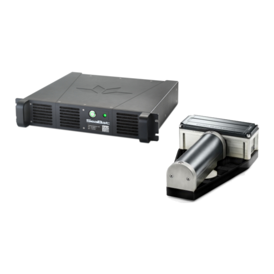
SeaBat T-Series Rackmount
SeaBat T20-R and T50-R High-Resolution
Multibeam Sonar System
OPERATOR'S MANUAL
Part Number 1008754
Version 9
December 2021
Use and Disclosure of Data
EU Uncontrolled Technology:
Information contained herein is uncontrolled under the EU-regulation no. 821 of 20 May 2021.
However, export, reexport or diversion contrary to law is prohibited.
Advertisement
Table of Contents

Related Manuals for Teledyne SeaBat T-Series


Summary of Contents for Teledyne SeaBat T-Series
- Page 1 SeaBat T-Series Rackmount SeaBat T20-R and T50-R High-Resolution Multibeam Sonar System OPERATOR'S MANUAL Part Number 1008754 Version 9 December 2021 Use and Disclosure of Data EU Uncontrolled Technology: Information contained herein is uncontrolled under the EU-regulation no. 821 of 20 May 2021.
- Page 2 (but not limited to) the implied warranties of merchant liability and fitness for a particular purpose. Teledyne RESON shall not be liable for errors contained herein or for incidental or consequential damages in connection with the furnishing, performance, or use of this material.
- Page 3 PREFACE – ABOUT THIS MANUAL This manual is designed to give detailed procedures for the correct installation, operation, and maintenance of the SeaBat T-Series Rackmount sonar system and is equally useful for both the first time user and the experienced technician.
- Page 4 (usually from a low to a high gain state) transmitter user interface WEEE Waste Electrical and Electronic Equipment Time and date identifier SeaBat T-Series Rackmount Operator's Manual Page iv December 15, 2021 Version 9 Uncontrolled Technology Subject to Restrictions Contained on the Cover Page.
-
Page 5: Table Of Contents
TABLE OF CONTENTS Introduction....................1 System Overview......................1 System Architecture ......................2 System Operation......................3 System Features ......................3 Typical Applications......................6 Available SeaBat T-Series Rackmount Configurations ............7 Safety Precautions ..................8 Operator Safety ........................8 Equipment Safety ......................8 2.2.1 Safe Handling ......................8 2.2.2 Cleaning and Maintenance ..................9 Corrosion Avoidance ......................11... - Page 6 A.3.2 Data Processing Warnings ..................68 A.3.3 Data Recording Warnings..................69 A.3.4 BITE Data Warnings ....................69 A.3.5 Input Signal Warnings.....................69 SeaBat T-Series Rackmount Operator's Manual Page vi December 15, 2021 Version 9 Uncontrolled Technology Subject to Restrictions Contained on the Cover Page.
- Page 7 POS MV – How to Perform a GAMS Calibration............103 F.1.1 MV-POSView – Standby Mode................103 F.1.2 GAMS Parameter Setup ..................103 SeaBat T-Series Rackmount Operator's Manual Page vii December 15, 2021 Version 9 Uncontrolled Technology Subject to Restrictions Contained on the Cover Page.
- Page 8 G.2.1 Configuring the Sonar UI to Output Data..............121 G.2.2 Configuring Teledyne PDS ...................122 Appendix H Reference Documentation...........125 SeaBat T-Series Rackmount Documentation...............125 SeaBat T-Series Rackmount Design Documents ............126 H.2.1 Receiver, EM7219 Outline..................128 H.2.2 Receiver, EM7218 Outline..................129 H.2.3 Projector, TC2181 Outline ..................130 H.2.4...
- Page 9 Teledyne RESON Support ...................176 LIST OF FIGURES Figure 1: SeaBat T-Series Rackmount System Configuration............2 Figure 2: SeaBat T-Series Rackmount System Configuration with Integrated INS (optional) ..2 Figure 3: Processor Filter Location....................11 Figure 4: Range Setting Diagrams ....................21 Figure 5: Range Setting – Too Long....................21 Figure 6: Range Setting –...
- Page 10 Figure 54: Flow around Single T50 with Fairing, Cross Section of Symmetry Plane ....61 Figure 55: Flow at 10 knots around Single T50 without Fairing.............62 Figure 56: Flow around Single T50 without Fairing, Cross Section of Symmetry Plane ....62 SeaBat T-Series Rackmount Operator's Manual Page x December 15, 2021 Version 9 Uncontrolled Technology Subject to Restrictions Contained on the Cover Page.
- Page 11 Figure 66: SVP, Motion, and Time Standard Connections ............88 Figure 67: SVP, Motion, and Time Connections with Integrated INS (optional) ......89 Figure 68: SeaBat T-Series Rackmount System Cables...............91 Figure 69: Required PPS Pulse Width...................98 Figure 70: PPS In Delay ........................99 Figure 71: PPS/Trigger Signal .......................99...
- Page 12 Table 18: TC2181 Projector Unit Technical Specifications............93 Table 19: PPS In and Trigger In Signals ..................98 Table 20: Theoretical Max. Data Rates – SeaBat T-Series Rackmount Single and Dual Head..100 Table 21: IP Configuration for RSP .....................101 Table 22: Sensor Offsets ......................110 Table 23: Sensor Alignments.......................111...
-
Page 13: Introduction
INTRODUCTION System Overview The SeaBat T-Series Rackmount sonar system is the newest addition to the leading SeaBat T-series product range, engineered from the ground up to evolve with your business. SeaBat T- Series Rackmount is designed for very fast mobilization on any type of survey vessels, securing minimal interfacing and low space requirements. -
Page 14: System Architecture
EM 7218 or EM 7219 TC 2181 Receiver(s) Projector(s) Figure 1: SeaBat T-Series Rackmount System Configuration The SeaBat T-Series Rackmount multibeam sonar systems are also available with an optional state-of-the-art built-in and fully integrated Inertial Navigation System (INS). Sonar UI hosted by CFE laptop/PC... -
Page 15: System Operation
RSP and generates the wedge, water column, snippets, and side-scan displays as well as other displays for sensor monitoring and general system Built-In Test Environment overview. System Features Table 1: SeaBat T-Series Rackmount Feature Pack Feature Base Optional Channel normalization ... - Page 16 Built-In Test Environment (BITE): BITE is an integral part of the SeaBat T-Series Rackmount sonar systems, monitoring the status of internal subsystems and the wet- end units.
- Page 17 Real-time QC display: The SeaBat T-Series Rackmount sonar systems generate a real- time display with an intensity image on the CFE monitor. Overlaid on this intensity image is the bottom detection display, giving the operator an excellent QC (quality control) tool.
-
Page 18: Typical Applications
(FM) transmit pulses which provides extended range performance (across all frequencies) and significantly improves system immunity to external noise. Typical Applications The SeaBat T-Series Rackmount is based around the sonar processor. The powerful scalable feature set provides unmatched utility across a wide range of applications including: As-built surveys ... -
Page 19: Available Seabat T-Series Rackmount Configurations
INTRODUCTION Available SeaBat T-Series Rackmount Configurations Table 2: SeaBat T-Series Rackmount Available Configurations Configuration Frequency (kHz) Depth rating (m) T20-R 88017004: T20-R single head 190-420 OPT-2060: change to RSP w/INS support 190-420 88017005: T20-R integrated dual head 190-420 OPT-2062: change to RSP w/INS support... -
Page 20: Safety Precautions
(see Appendix J Standard Warranty Information). Operator Safety The SeaBat T-Series Rackmount system should be handled with attention to operator safety as well as protection of the hardware components. General precautions include: DO NOT connect or disconnect cables with the power on. -
Page 21: Cleaning And Maintenance
To scrape away marine growth from the arrays, use only a wooden tool. Do not apply any antifouling paint on the acoustic window unless the type is recommended by Teledyne RESON. The antifouling paint will affect the acoustic performance. Teledyne RESON recommends: o For high-frequency transducers (>100kHz) use ClearSignal. - Page 22 Do not overtighten bulkhead nuts. Grip main body of connector during mating or unmating. Do not pull on cable to disconnect. Avoid sharp bends at cable entry to connector. SeaBat T-Series Rackmount Operator's Manual Page 10 December 15, 2021 Version 9...
-
Page 23: Corrosion Avoidance
We therefore recommend electrical isolation between the sonar head and mounting structure. CAUTION Do not use sacrificial anodes on a SeaBat™ bracket. Sacrificial anodes lead to unwanted cathodic reaction and does not offer electrical isolation. SeaBat T-Series Rackmount Operator's Manual Page 11 December 15, 2021 Version 9... -
Page 24: Electrical Isolation
Teledyne RESON recommends using the standard bracket delivered with the system. The standard bracket is made of high-strength fiber reinforced material and will therefore isolate the sonar head completely from the mounting arrangement. -
Page 25: Ce Marking
SAFETY PRECAUTIONS CE Marking This product carries the CE mark that indicates that it conforms to the essential health, safety, and environmental requirements of the relevant European Directives. SeaBat T-Series Rackmount Operator's Manual Page 13 December 15, 2021 Version 9... -
Page 26: System Startup And Shutdown
For information on user interface navigation, refer to the RESON Sonar UI User Manual (see Appendix H Reference Documentation). For information on the practical use of the sonar, see section 5 Active Sonar Usage. SeaBat T-Series Rackmount Operator's Manual Page 14 December 15, 2021 Version 9 Uncontrolled Technology Subject to Restrictions Contained on the Cover Page. -
Page 27: System Startup Instructions
The sonar system can be identified by its serial number (prefixed with SN) next to the IP address. The serial number can be found on the front of the RSP. SeaBat T-Series Rackmount Operator's Manual Page 15 December 15, 2021 Version 9 Uncontrolled Technology Subject to Restrictions Contained on the Cover Page. - Page 28 RSP by pressing the power button. Select the settings appropriate for the present survey mission. Refer to the RESON Sonar UI User Manual (see Appendix H Reference Documentation). SeaBat T-Series Rackmount Operator's Manual Page 16 December 15, 2021 Version 9 Uncontrolled Technology Subject to Restrictions Contained on the Cover Page.
-
Page 29: System Shutdown Instructions
Click the cross in the upper right corner of the Sonar UI to terminate the session. The Sonar UI will resynchronize to the RSP, once the system is started again. SeaBat T-Series Rackmount Operator's Manual Page 17 December 15, 2021 Version 9 Uncontrolled Technology Subject to Restrictions Contained on the Cover Page. -
Page 30: System Wake Up
Sonar UI has been connected to the system (via the sonar address drop-down menu). RSP has remained connected to mains power. LAN 1 port is used. SeaBat T-Series Rackmount Operator's Manual Page 18 December 15, 2021 Version 9 Uncontrolled Technology Subject to Restrictions Contained on the Cover Page. -
Page 31: System Configuration And Operation
DFD. Refer to the appendix section in the Data Format Definition document for example code for writing the control application (see appendix H.1 SeaBat T- Series Rackmount Documentation). SeaBat T-Series Rackmount Operator's Manual Page 19 December 15, 2021 Version 9 Uncontrolled Technology Subject to Restrictions Contained on the Cover Page. -
Page 32: Active Sonar Usage
For information on user interface navigation, refer to the RESON Sonar UI User Manual (see Appendix H Reference Documentation). For information on installation, see Appendix B Installation Instructions. SeaBat T-Series Rackmount Operator's Manual Page 20 December 15, 2021 Version 9... -
Page 33: Enhancing Sonar Performance
Range should be set correctly, and the ping rate should be capped using Max rate. Refer to the RESON Sonar UI User Manual (see Appendix H Reference Documentation.) SeaBat T-Series Rackmount Operator's Manual Page 21 December 15, 2021 Version 9 Uncontrolled Technology Subject to Restrictions Contained on the Cover Page. -
Page 34: Transmit Power
With the transmit power OFF, the sonar system will act as a passive sonar by only receiving data. This feature is very useful for monitoring the ambient water in order to assess the level of background noise and interference from the vessel itself. SeaBat T-Series Rackmount Operator's Manual Page 22 December 15, 2021 Version 9 Uncontrolled Technology Subject to Restrictions Contained on the Cover Page. -
Page 35: Ping Rate
(sample) and is available in record 7010. Refer to the Data Format Definition document for information (see Appendix H Reference Documentation). The generation of the TVG curve is based on the formula in Table 4. SeaBat T-Series Rackmount Operator's Manual Page 23 December 15, 2021 Version 9 Uncontrolled Technology Subject to Restrictions Contained on the Cover Page. -
Page 36: Frequency Selection
For instructions on how to adjust this setting, refer to the RESON Sonar UI User Manual (see Appendix H Reference Documentation). NOTE The Pulse Length adjusts itself automatically when Tracker is selected (see also section 5.3.2 below). SeaBat T-Series Rackmount Operator's Manual Page 24 December 15, 2021 Version 9... -
Page 37: Pulse Type
For instructions on how to adjust this setting, refer to the Sonar UI User Manual (see Appendix H Reference Documentation). FlexMode is an optional add-on feature (see Table 1). SeaBat T-Series Rackmount Operator's Manual Page 25 December 15, 2021 Version 9... -
Page 38: Figure 8: Example Of Reduced Swath Width
Operating on 50m range scale Ping rate 10Hz 22.5° Seafloor at 35m depth Figure 8: Example of Reduced Swath Width SeaBat T-Series Rackmount Operator's Manual Page 26 December 15, 2021 Version 9 Uncontrolled Technology Subject to Restrictions Contained on the Cover Page. -
Page 39: Figure 9: Horizontal Swath Steering
85° 55° With a swath of 60°, the maximum steering angle is ±55° (85°-(swath/2)). Figure 9: Horizontal Swath Steering SeaBat T-Series Rackmount Operator's Manual Page 27 December 15, 2021 Version 9 Uncontrolled Technology Subject to Restrictions Contained on the Cover Page. -
Page 40: Use Of Beam Mode
The system can also hold constant seafloor spacing between beams to provide the same high-quality results with minimal data volume. SeaBat T-Series Rackmount Operator's Manual Page 28 December 15, 2021 Version 9 Uncontrolled Technology Subject to Restrictions Contained on the Cover Page. - Page 41 Very wide spacing at large angles Intermediate (compromise): o Moderate beam number o Moderate spacing at large angles SeaBat T-Series Rackmount Operator's Manual Page 29 December 15, 2021 Version 9 Uncontrolled Technology Subject to Restrictions Contained on the Cover Page.
-
Page 42: Use Of Gates
15-20% (of depth). This value should be increased over rougher terrain or over a rapidly changing sea floor where bathymetry is extreme in the vertical values. SeaBat T-Series Rackmount Operator's Manual Page 30 December 15, 2021 Version 9 Uncontrolled Technology Subject to Restrictions Contained on the Cover Page. -
Page 43: Figure 12: Depth Gates, With No Roll
Sonar head MinDepth MaxDepth Figure 13: Depth Gates, With Roll SeaBat T-Series Rackmount Operator's Manual Page 31 December 15, 2021 Version 9 Uncontrolled Technology Subject to Restrictions Contained on the Cover Page. -
Page 44: Figure 14: Depth Gates, With Roll And Motion Sensor Input
Appendix H Reference Documentation). Manual gates with 0° tilt on a sloping seafloor Manual gates with -15° tilt on a sloping seafloor Figure 15: Depth Gate Tilt SeaBat T-Series Rackmount Operator's Manual Page 32 December 15, 2021 Version 9 Uncontrolled Technology Subject to Restrictions Contained on the Cover Page. -
Page 45: Maximizing Quality Of Backscatter For Snippets Data
As highlighted in the report “Backscatter measurements by seafloor-mapping sonars” by the GeoHab Backscatter Working Group. Multi-detect is an optional add-on feature (see Table 1). SeaBat T-Series Rackmount Operator's Manual Page 33 December 15, 2021 Version 9... -
Page 46: Tracker Autopilot
Under zero roll conditions, the swath is vertical and the center of the swath is directly below the vessel. Figure 17: Swath under Zero Roll Conditions SeaBat T-Series Rackmount Operator's Manual Page 34 December 15, 2021 Version 9 Uncontrolled Technology Subject to Restrictions Contained on the Cover Page. -
Page 47: Head Tilt
ROV are inclined inwards to maximize the number of hits on a pipe. Another application is survey of harbor walls where the desire is to survey as close to the waterline as possible. SeaBat T-Series Rackmount Operator's Manual Page 35 December 15, 2021 Version 9 Uncontrolled Technology Subject to Restrictions Contained on the Cover Page. -
Page 48: Figure 20: Head Tilt Functionality
Pipe Inspection with Dual Head System In this application, each head is typically tilted up to 15° (max. setting is +/-45°) from normal, generally looking “in”. Figure 22: Head Tilt for Pipe Inspection SeaBat T-Series Rackmount Operator's Manual Page 36 December 15, 2021 Version 9... -
Page 49: Compensation For Environmental Conditions
Appendix H Reference Documentation). Note, that absorption and attenuation of sound in the water column caused by microbubbles and species such as, e.g., plankton and fish is not included in this consideration. SeaBat T-Series Rackmount Operator's Manual Page 37 December 15, 2021 Version 9 Uncontrolled Technology Subject to Restrictions Contained on the Cover Page. -
Page 50: Loss Of Sound By Spreading
1/R. As the sound is scattered back to the sonar the backscattered field also decreases as 1/R. Consequently, for a two-travel path the acoustic pressure in a free field decays as 1/R SeaBat T-Series Rackmount Operator's Manual Page 38 December 15, 2021 Version 9 Uncontrolled Technology Subject to Restrictions Contained on the Cover Page. -
Page 51: Sound Velocity
30 ppt temperatures and salinity. 1420 35 ppt 1400 Temperature (degrees C) Figure 24: Typical Sound Velocity Values SeaBat T-Series Rackmount Operator's Manual Page 39 December 15, 2021 Version 9 Uncontrolled Technology Subject to Restrictions Contained on the Cover Page. -
Page 52: Limitations
The following subsections provide examples of different kinds of limitations. 5.5.1 Cavitation Some reduction in the transmitted source level is expected to be caused by cavitation. For means of compensating for this, see subsections in 5.2 above. SeaBat T-Series Rackmount Operator's Manual Page 40 December 15, 2021 Version 9... -
Page 53: Machinery Noise
A poorly designed sonar fairing can degrade the system performance by a factor of 4 for speeds above 8-10 knots. Typically, this noise source is the most common problem on all sonar installations. SeaBat T-Series Rackmount Operator's Manual Page 41... -
Page 54: Air Bubbles
5.5.6 Environment A high-reverb environment where echoes of the previous ping are contaminating the current ping may prove to be difficult. For means of compensating for this, see section 5.2.3 above. SeaBat T-Series Rackmount Operator's Manual Page 42 December 15, 2021 Version 9 Uncontrolled Technology Subject to Restrictions Contained on the Cover Page. -
Page 55: System Performance And Data Types
Costs for this survey may be quoted as part of a contract or independently. The SeaBat T-Series Rackmount sonar systems produce four types of data, bathymetry, side- scan, snippets backscatter and water column backscatter, suitable for the generation of high- resolution hydrographic charts that exceed international standards. -
Page 56: Table 5: Seabat T-Series Rackmount System Performance
SYSTEM PERFORMANCE AND DATA TYPES Table 5: SeaBat T-Series Rackmount System Performance Parameters 400kHz 200kHz Frequency range 190-420kHz (CW) / 200-400kHz (FM) Across-track receive beam widths* T20: 1.0° T20: 2° (nominal values) T50: 0.5° T50: 1° Along-track transmit beam widths 1°... -
Page 57: System Components
Displays the sonar image and the detected seabed as well as the sonar control user interface. Generates the various data telegrams to be recorded by data acquisition systems. Supports optional beam data storage on a large, external RAID array. SeaBat T-Series Rackmount Operator's Manual Page 45 December 15, 2021 Version 9... -
Page 58: Em7218 Receiver Unit
100% bottom coverage even at high vessel speed. For physical specifications, see appendix B.7.3 TC2181 Projector Unit. Rear view Figure 28: TC2181 Projector Unit SeaBat T-Series Rackmount Operator's Manual Page 46 December 15, 2021 Version 9 Uncontrolled Technology Subject to Restrictions Contained on the Cover Page. -
Page 59: Selectable Beam Density
140/150 For examples on how to use this feature, see section 5.2.9 Use of Beam Mode. FlexMode is an optional add-on feature (see Table 1). FlexMode requires Max. Beam license. SeaBat T-Series Rackmount Operator's Manual Page 47 December 15, 2021 Version 9 Uncontrolled Technology Subject to Restrictions Contained on the Cover Page. -
Page 60: Equi-Distant, Equi-Angle, And Intermediate Modes
±65° the beam density is approximately 2.5 times greater than at nadir. SeaBat T-Series Rackmount Operator's Manual Page 48 December 15, 2021 Version 9 Uncontrolled Technology Subject to Restrictions Contained on the Cover Page. -
Page 61: Figure 31: Beam Spacing
Figure 32 shows the difference in distribution between equiangular and equidistant spacing. Figure 32: Across-Track Sounding Location on a Flat Bottom SeaBat T-Series Rackmount Operator's Manual Page 49 December 15, 2021 Version 9 Uncontrolled Technology Subject to Restrictions Contained on the Cover Page. -
Page 62: Data Types
Data Types 6.3.1 Bathymetry Data The SeaBat T-Series Rackmount system generates between 10 and 1024 soundings per ping. The system broadcasts from the sonar processor to the data acquisition software, where they are corrected for mechanical offsets, motion, heading, refraction, tide or depth, and position. To perform these corrections, the appropriate sensors must be interfaced to the data acquisition software. -
Page 63: Figure 33: Graphic Illustration Of Snippets Data
An accurate calculation of the sediment backscattering strength requires a detailed knowledge of the sonar characteristics and of the environment. Teledyne RESON’s normalized backscatter process, available across the entire frequency range, is applied to the snippet record to generate a magnitude signal that is compensated for the characteristics of the sonar providing the operator with information that depends only on the environment (seafloor). -
Page 64: Real-Time Pipe Detection And Tracking
While Teledyne RESON uses generic parameters to characterize the sonar, we take great pride in our very tight manufacturing tolerances to ensure that these parameters truly represent each unit. -
Page 65: Multi-Detect
Multi-detect is an optional add-on feature (see Table 1). X-Range is an optional add-on feature (see Table 1). FRDH is available as an upgrade to the Base license set (see Table 1). SeaBat T-Series Rackmount Operator's Manual Page 53 December 15, 2021 Version 9 Uncontrolled Technology Subject to Restrictions Contained on the Cover Page. -
Page 66: Quality
For instructions on how to display the test results, refer to the Sonar UI User Manual (see Appendix H Reference Documentation). Adaptive gate Bottom detection point Comparison window Figure 40: Brightness Test SeaBat T-Series Rackmount Operator's Manual Page 54 December 15, 2021 Version 9 Uncontrolled Technology Subject to Restrictions Contained on the Cover Page. -
Page 67: Colinearity Test
(number of samples) by the detection point (fractional sample number). For example: Absolute range error: 0.8 samples Fractional sample number of detection point: 120.2 Uncertainty = 0.8/120.2 = 0.006655574 SeaBat T-Series Rackmount Operator's Manual Page 55 December 15, 2021 Version 9... -
Page 68: Hydrodynamic Drag
In general, Teledyne RESON recommends the use of the optional fairing to maintain a steady water flow around the array and reduce load on the pole/bracket. -
Page 69: Drag Simulation Results
The same situation without front fairing is shown in Figure 46. Figure 44: Flow around Single T20 with Fairing, Cross Section of Symmetry Plane SeaBat T-Series Rackmount Operator's Manual Page 57 December 15, 2021 Version 9 Uncontrolled Technology Subject to Restrictions Contained on the Cover Page. -
Page 70: Figure 45: Flow At 10 Knots Around Single T20 Without Fairing
The same situation with front fairing is shown in Figure 44. Figure 46: Flow around Single T20 without Fairing, Cross Section of Symmetry Plane SeaBat T-Series Rackmount Operator's Manual Page 58 December 15, 2021 Version 9 Uncontrolled Technology Subject to Restrictions Contained on the Cover Page. -
Page 71: Figure 47: T20 Dual Sonar Head Assembly In Bracket With Optional Front Fairing
The same situation without front fairings is shown in Figure 51. Figure 49: Flow around Dual T20 with Fairings, Cross Section of Symmetry Plane SeaBat T-Series Rackmount Operator's Manual Page 59 December 15, 2021 Version 9 Uncontrolled Technology Subject to Restrictions Contained on the Cover Page. -
Page 72: Figure 50: Flow At 10 Knots Around Dual T20 Without Fairings
The same situation with front fairings is shown in Figure 49. Figure 51: Flow around Dual T20 without Fairings, Cross Section of Symmetry Plane SeaBat T-Series Rackmount Operator's Manual Page 60 December 15, 2021 Version 9 Uncontrolled Technology Subject to Restrictions Contained on the Cover Page. -
Page 73: Figure 52: T50 Sonar Head Assembly In Bracket With Optional Front Fairing
The same situation without front fairing is shown in Figure 56. Figure 54: Flow around Single T50 with Fairing, Cross Section of Symmetry Plane SeaBat T-Series Rackmount Operator's Manual Page 61 December 15, 2021 Version 9 Uncontrolled Technology Subject to Restrictions Contained on the Cover Page. -
Page 74: Figure 55: Flow At 10 Knots Around Single T50 Without Fairing
The same situation with front fairing is shown in Figure 54. Figure 56: Flow around Single T50 without Fairing, Cross Section of Symmetry Plane SeaBat T-Series Rackmount Operator's Manual Page 62 December 15, 2021 Version 9 Uncontrolled Technology Subject to Restrictions Contained on the Cover Page. -
Page 75: Figure 57: T50 Dual Sonar Head Assembly In Bracket With Optional Front Fairing
The same situation without front fairings is shown in Figure 61. Figure 59: Flow around Dual T50 with Fairings, Cross Section of Symmetry Plane SeaBat T-Series Rackmount Operator's Manual Page 63 December 15, 2021 Version 9 Uncontrolled Technology Subject to Restrictions Contained on the Cover Page. -
Page 76: Figure 60: Flow At 10 Knots Around Dual T50 Without Fairings
The same situation with front fairings is shown in Figure 59. Figure 61: Flow around Dual T50 without Fairings, Cross Section of Symmetry Plane SeaBat T-Series Rackmount Operator's Manual Page 64 December 15, 2021 Version 9 Uncontrolled Technology Subject to Restrictions Contained on the Cover Page. -
Page 77: Ping Rate Table
15.0 14.4 13.9 13.0 10.7 10.4 10.1 1.25 The ping rate is limited to 50p/s (see Table 4). SeaBat T-Series Rackmount Operator's Manual Page 65 December 15, 2021 Version 9 Uncontrolled Technology Subject to Restrictions Contained on the Cover Page. -
Page 78: Appendix A Troubleshooting
Error Messages NOTE The error messages listed in this section are accurate up to the document release date. For a complete list of up-to-date error messages, contact Teledyne RESON Customer Support (reson-support@teledyne.com). Errors are marked with a red in the Messages pane. -
Page 79: Data Reading Errors
Check 1 PPS input Time stamping will be done using system time only. 1 millisecond accuracy not possible. SeaBat T-Series Rackmount Operator's Manual Page 67 December 15, 2021 Version 9 Uncontrolled Technology Subject to Restrictions Contained on the Cover Page. -
Page 80: Normalization Errors
Warning Messages NOTE The warning messages listed in this section are accurate up to the document release date. For a complete list of up-to-date warning messages, contact Teledyne RESON Customer Support (reson-support@teledyne.com). Warnings are marked with a yellow in the Messages pane. -
Page 81: Data Recording Warnings
GPS output. If incorrect time stamp of data. uncorrected sonar data cannot be time stamped to 1 millisecond. SeaBat T-Series Rackmount Operator's Manual Page 69 December 15, 2021 Version 9 Uncontrolled Technology Subject to Restrictions Contained on the Cover Page. -
Page 82: Data Subscription Warnings
Trigger out offset (x) is invalid Trigger out offset + length (x) exceed limit of 20ms SeaBat T-Series Rackmount Operator's Manual Page 70 December 15, 2021 Version 9 Uncontrolled Technology Subject to Restrictions Contained on the Cover Page. -
Page 83: Error Messages - Master List In Alphabetical Order
Could not create PCI server Software detected a failure to configure the main Reboot the PC, call Teledyne RESON support. General System data acquisition and distribution module (PCI). Startup This can be caused by errors in the configuration files, or corrupted installation. - Page 84 Reboot the system. Input Signal (Timing software installation. is not supported and Triggers) Contact Teledyne RESON Customer Support if the problem persists. Failed to register external trigger, ERROR = External Trigger Firmware cannot be initialized or Reboot the system. Input Signal (Timing is not supported.
- Page 85 Windows has failed to allocate a network Check network permissions and resources or General System resource. reinstall operating system. Startup SeaBat T-Series Rackmount Operator's Manual Page 73 December 15, 2021 Version 9 Uncontrolled Technology Subject to Restrictions Contained on the Cover Page.
-
Page 86: Warning Messages - Master List In Alphabetical Order
Check user permissions and available disk space. Data Recording have occurred in conjunction with data recording. Check file names and recording directories SeaBat T-Series Rackmount Operator's Manual Page 74 December 15, 2021 Version 9 Uncontrolled Technology Subject to Restrictions Contained on the Cover Page. - Page 87 The software was unable to send data to a Check network resources and user permissions. Data Subscription connected client. SeaBat T-Series Rackmount Operator's Manual Page 75 December 15, 2021 Version 9 Uncontrolled Technology Subject to Restrictions Contained on the Cover Page.
- Page 88 A connected client has sent an unrecognized Review client software source code or definitions Network Components command to the software. for correct implementation of Teledyne RESON 7k Data Format. TCP Server - Warning max connections The network module has become saturated with Close some of the connected clients.
- Page 89 Restart the software. Reboot PC. System Stability DROPPING ping has been lost because the processing queue is full. SeaBat T-Series Rackmount Operator's Manual Page 77 December 15, 2021 Version 9 Uncontrolled Technology Subject to Restrictions Contained on the Cover Page.
-
Page 90: Appendix Binstallation Instructions
INSTALLATION INSTRUCTIONS APPENDIX B INSTALLATION INSTRUCTIONS Components List Table 8: SeaBat T-Series Rackmount Components Part Number Description 85002319 Projector,TC2181, DF200/400kHz 85002409 or Receiver, EM7218, 256Ch, 200-400kHz, TI (T50) 85002436 Receiver, EM7219, 128Ch, 200-400kHz,TI (T20) 85160031 MOUNTING BRACKET STANDARD, T20 85160033... - Page 91 1010756 Cable Assy, Antenna cable, TNC to TNC on LMR-240 Cable, XX=20m 1010757 Cable Assy, Antenna cable, TNC to TNC on LMR-240 Cable, XX=40m SeaBat T-Series Rackmount Operator's Manual Page 79 December 15, 2021 Version 9 Uncontrolled Technology Subject to Restrictions Contained on the Cover Page.
-
Page 92: Installation Checklist
Appendix H Reference Documentation). CAUTION Before turning the system on, make sure that there is no significant difference between the temperatures of the equipment and environment in order to prevent condensation. SeaBat T-Series Rackmount Operator's Manual Page 80 December 15, 2021 Version 9... -
Page 93: System Interfacing
Appendix B.4 Dry-End Installation Appendix B.7 Wet-End Installation, incl. o B.7.8 Hardware Section 3.3 Starting the Sonar User Interface SeaBat T-Series Rackmount Operator's Manual Page 81 December 15, 2021 Version 9 Uncontrolled Technology Subject to Restrictions Contained on the Cover Page. -
Page 94: Figure 62: T20/50-R, Single/Dual-Head Interfacing Diagram
TROUBLESHOOTING Figure 62: T20/50-R, single/dual-head interfacing diagram SeaBat T-Series Rackmount Operator's Manual Page 82 December 15, 2021 Version 9 Uncontrolled Technology Subject to Restrictions Contained on the Cover Page. -
Page 95: Interfacing Diagram For Configurations With Integrated Ins
Appendix B.4 Dry-End Installation Appendix B.7 Wet-End Installation, incl. o B.7.8 Hardware Section 3.3 Starting the Sonar User Interface SeaBat T-Series Rackmount Operator's Manual Page 83 December 15, 2021 Version 9 Uncontrolled Technology Subject to Restrictions Contained on the Cover Page. -
Page 96: Figure 63: T20/50-R With Integrated Ins, Single/Dual-Head Interfacing Diagram
TROUBLESHOOTING Figure 63: T20/50-R with integrated INS, single/dual-head interfacing diagram SeaBat T-Series Rackmount Operator's Manual Page 84 December 15, 2021 Version 9 Uncontrolled Technology Subject to Restrictions Contained on the Cover Page. -
Page 97: Dry-End Installation
CAUTION The RSP is designed and assembled specifically to accommodate the software packages provided by Teledyne RESON and installed at the factory. Installing additional software on this machine can result in decreased performance and/or system malfunction. Do not open, change, add, or remove anything (incl. software) on the RSP. -
Page 98: Sonar Processor Cable Connections
INSTALLATION INSTRUCTIONS B.4.3 Sonar Processor Cable Connections All dry-end cables provided by Teledyne RESON come with factory-installed connectors to be attached at the appropriate port(s) on the rear panel of the rack-mounted sonar processor (RSP). CAUTION Do not disconnect any cables from the rear of the RSP while the unit is running. This can damage the internal workings of the unit. -
Page 99: Rack-Mounted Sonar Processor Power Button And Bite Led
Yellow: BITE warning (investigate UI on surveyor laptop/PC to find the cause) o Red: BITE error (investigate UI on surveyor laptop/PC to find the cause) o Red flashing: 7kCenter not responding SeaBat T-Series Rackmount Operator's Manual Page 87 December 15, 2021 Version 9 Uncontrolled Technology Subject to Restrictions Contained on the Cover Page. -
Page 100: Auxiliary Sensors
Trig out pulse Sound velocity COM 3 SVP in data Figure 66: SVP, Motion, and Time Standard Connections SeaBat T-Series Rackmount Operator's Manual Page 88 December 15, 2021 Version 9 Uncontrolled Technology Subject to Restrictions Contained on the Cover Page. -
Page 101: Seabat T20/50-R Configurations With Integrated Ins
Connect the DB9 to the port marked SVP Com 3 on the rear panel of the RSP (see item 8 in Figure 64 or Figure 65). Connect a Teledyne RESON standard SVP Shorted internally cable with a Fischer connector to the port marked SVP (see item 9 in Figure 64 or Figure 65). -
Page 102: Time Output (For Optional Ins Configurations)
Table 15: RSP Ports “Com 4”, “Com 3-5” for optional INS DB9 Pin RS-232 1-4-6 Shorted internally Shorted internally SeaBat T-Series Rackmount Operator's Manual Page 90 December 15, 2021 Version 9 Uncontrolled Technology Subject to Restrictions Contained on the Cover Page. -
Page 103: Seabat T-Series Rackmount Cables
INSTALLATION INSTRUCTIONS SeaBat T-Series Rackmount Cables A standard cable set is provided to connect the SeaBat T-Series Rackmount system components. EM7218 or EM7219 receiver(s) laptop/PC Rack-mounted Sonar Processor (RSP) TC2181 (optional) projector(s) Antennas TC2187 (optional) ER projector(s) (optional) Figure 68: SeaBat T-Series Rackmount System Cables ... -
Page 104: Wet-End Installation
For ease of mounting, the ends of the housing are labeled P and S for Port and Starboard, respectively. The connector is placed on the port side. CAUTION Ensure free access to water inlet holes (on starboard side) for pressure equalization. SeaBat T-Series Rackmount Operator's Manual Page 92 December 15, 2021 Version 9... -
Page 105: Tc2181 Projector Unit (Pn 85002319)
The cable can be arranged as needed in the grooves designed specifically for this purpose. NOTE TC2181 projectors with the label “SV2/T” below the part no. on the housing are compatible with SeaBat 7125 SV2 and SeaBat T-Series systems. B.7.4 Wet-End Cable Connections... -
Page 106: Sonar Head Assembly Orientation
For T50: Figure 84: T50 Bracket Installation: Sonar Reference Point. It is important to note that the sonar reference point may not be a physical point on the sonar system. SeaBat T-Series Rackmount Operator's Manual Page 94 December 15, 2021 Version 9 Uncontrolled Technology Subject to Restrictions Contained on the Cover Page. -
Page 107: Wet-End Mounting
NOTE Fairings can also be used to improve hydrodynamic performance (see section 6.10 Hydrodynamic Drag and appendix H.2 SeaBat T-Series Rackmount Design Documents). The sonar head is not designed to be hydrodynamic at speeds in excess of two knots. Vibration and oscillation will become evident, if the projector and receiver are not rigidly mounted. -
Page 108: Hardware
For examples on how to use this feature, see section 5.3.4 Head Tilt. o The angular value is entered in degrees (+ Port up/- Port down) and must be between -45° and 45° in increments of 0.5°. SeaBat T-Series Rackmount Operator's Manual Page 96 December 15, 2021 Version 9 Uncontrolled Technology Subject to Restrictions Contained on the Cover Page. -
Page 109: System Check
INSTALLATION INSTRUCTIONS System Check Once the SeaBat T-Series Rackmount has been installed, follow these steps to ensure that the system is working properly. For information on the settings, refer to the RESON Sonar UI User Manual (see Appendix H Reference Documentation). -
Page 110: Appendix Cpps In And Trigger In
Figure 69: Required PPS Pulse Width Measured at the BNC terminals. Voltages beyond maximum limits may cause permanent damage to the input. Completely unconnected input guaranteed to be low. SeaBat T-Series Rackmount Operator's Manual Page 98 December 15, 2021 Version 9... -
Page 111: Hints And Advice
* The TRIG IN//PPS IN (or 1PPS) ports are clearly marked on the rear panel of the sonar processor. Figure 71: PPS/Trigger Signal SeaBat T-Series Rackmount Operator's Manual Page 99 December 15, 2021 Version 9 Uncontrolled Technology Subject to Restrictions Contained on the Cover Page. -
Page 112: Appendix Ddata Rates
DATA RATES APPENDIX D DATA RATES Table 20: Theoretical Max. Data Rates – SeaBat T-Series Rackmount Single and Dual Head System Utilized storage Max. data rate Utilized storage and number of beams GB/hour Mb/s GB/hour T20/50-R, 256 beams 34kS/s ~130... -
Page 113: Appendix Enetwork Configuration
Please find the serial number (with seven digits) on the front label on the RSP. For details on INS configuration, see Appendix F Configuration of Integrated INS (optional). SeaBat T-Series Rackmount Operator's Manual Page 101 December 15, 2021 Version 9... - Page 114 In the event of a problem, connect a cable directly between the LAN 2 port on the RSP and the laptop/PC, change the laptop/PC to IP address 10.11.10.10 with subnet 255.255.255.0, and restart the SUI. It might be necessary to reboot the laptop/PC as well. SeaBat T-Series Rackmount Operator's Manual Page 102 December 15, 2021 Version 9 Uncontrolled Technology Subject to Restrictions Contained on the Cover Page.
-
Page 115: Appendix F Configuration Of Integrated Ins (Optional)
GAMS Parameter Setup Prior to a GAMS calibration any existing GAMS vector parameters should be zeroed out. Record the previous settings prior to zeroing. Choose Settings > Installation > GAMS Param. Setup. SeaBat T-Series Rackmount Operator's Manual Page 103 December 15, 2021 Version 9 Uncontrolled Technology Subject to Restrictions Contained on the Cover Page. -
Page 116: Positioning Quality
The GAMS calibration is best performed with highest positional reliability. This means that Nav Status should read at best FIXED RTK or RTCM DGPS if RTK is not available. Ensure that differential corrections are received before commencing a GAMS calibration. SeaBat T-Series Rackmount Operator's Manual Page 104 December 15, 2021 Version 9 Uncontrolled Technology Subject to Restrictions Contained on the Cover Page. -
Page 117: Gams Calibration - Procedure
During the vessel maneuvers, monitor the Heading Accuracy as indicated below. After clicking Standby it will momentarily reset to 55.000. During the vessel maneuvers it will start to decrease, at first rapidly then slowing as the accuracy reaches its limit. SeaBat T-Series Rackmount Operator's Manual Page 105 December 15, 2021 Version 9 Uncontrolled Technology Subject to Restrictions Contained on the Cover Page. - Page 118 Choose Settings > GAMS Calibration Control > Start. The message CAL in Progress will appear. Continue to remain on standstill (or slow speed) on constant heading until the calibration is complete. The process will take less than 5 minutes. SeaBat T-Series Rackmount Operator's Manual Page 106 December 15, 2021 Version 9...
- Page 119 10.11.10.11 12. Choose Settings – Save Settings. 13. Choose File – Save POS Config. SeaBat T-Series Rackmount Operator's Manual Page 107 December 15, 2021 Version 9 Uncontrolled Technology Subject to Restrictions Contained on the Cover Page.
- Page 120 15. Note down the results. 16. The process should be repeated twice and the results from each calibration compared. They should agree to better than 5mm for each baseline vector component. SeaBat T-Series Rackmount Operator's Manual Page 108 December 15, 2021 Version 9 Uncontrolled Technology Subject to Restrictions Contained on the Cover Page.
-
Page 121: Pos Mv - How To Set Up For A Multibeam Survey
IMU whose origin is the IMU reference point as marked on the top. The accelerometers are assumed to be co-aligned with the machined housing of the IMU. SeaBat T-Series Rackmount Operator's Manual Page 109 December 15, 2021 Version 9 Uncontrolled Technology Subject to Restrictions Contained on the Cover Page. -
Page 122: Offsets - Example
Under ideal circumstances the IMU should be mounted on the center line of the vessel close to the center of rotation/gravity. The IMU reference mark may then become the CRP. SeaBat T-Series Rackmount Operator's Manual Page 110 December 15, 2021 Version 9 Uncontrolled Technology Subject to Restrictions Contained on the Cover Page. -
Page 123: Alignments - Example
F.2.5 MV-POSView Software The POS MV is configured by running the MV-POSView software. 10.11.10.11 SeaBat T-Series Rackmount Operator's Manual Page 111 December 15, 2021 Version 9 Uncontrolled Technology Subject to Restrictions Contained on the Cover Page. -
Page 124: Installation Parameters - Lever Arms & Mounting Angles
Y is the pitch alignment and Z is the heading alignment in the Tate/Bryant system. If the IMU and reference frames are perfectly co-aligned e.g. by means of an adjustable mounting plate then these values will all be zeros (as in the above example). SeaBat T-Series Rackmount Operator's Manual Page 112 December 15, 2021 Version 9 Uncontrolled Technology Subject to Restrictions Contained on the Cover Page. -
Page 125: Installation Parameters - Sensor Mounting
If the POS is receiving an external differentially corrected position message (e.g. GGA) as aiding, then the offsets for this antenna are required and are configured under Auxiliary GPS. SeaBat T-Series Rackmount Operator's Manual Page 113 December 15, 2021 Version 9 Uncontrolled Technology Subject to Restrictions Contained on the Cover Page. -
Page 126: Installation Parameters - Tags, Multipath & Autostart
Installation Parameters – Heave Filter Set the heave filter appropriately for the vessel. Choose Settings > Heave… For a small vessel enter 10 seconds. For a large vessel enter 20 seconds. SeaBat T-Series Rackmount Operator's Manual Page 114 December 15, 2021 Version 9 Uncontrolled Technology Subject to Restrictions Contained on the Cover Page. -
Page 127: Pos Mv Output- Serial Data
COM 1 – ZDA Time Sync, NMEA (PRECONFIGURED) To synchronize Teledyne PDS and/or a SeaBat 7k sonar it is necessary to generate an NMEA ZDA (UTC time) output message from one of the serial ports. Select the desired baud rate and communication parameters, choose NMEA from Output Select and click the $INZDA checkbox. - Page 128 Input/Output Ports Set-up COM 2 –Attitude/Motion, Binary (PRECONFIGURED) To synchronize Teledyne PDS and/or a SeaBat 7k sonar it is necessary to generate a binary motion output from one of the serial ports. Select the desired baud rate and communication parameters, choose Binary from Output Select and select the TSS1 format from the Formula Select drop-down menu.
-
Page 129: Pos Mv Output- Ethernet Realtime
POS has not changed – it is still true heading of Vessel frame. The roll and pitch patch test results may be entered either in the X and Y fields of the “Sensor 1 Frame w.r.t. Ref. Frame” SeaBat T-Series Rackmount Operator's Manual Page 117... -
Page 130: Pos Statistics
Ensure that a screen capture is taken of the Statistics page for record keeping purposes. This displays information such as software versions, serial numbers and enabled options. Choose View – Statistics… SeaBat T-Series Rackmount Operator's Manual Page 118 December 15, 2021 Version 9 Uncontrolled Technology Subject to Restrictions Contained on the Cover Page. -
Page 131: Appendix Ginterfacing Sensors To Teledyne Pds
Select Change adapter settings in the navigation pane. Open the Local Area Connection. Select Properties. Select Internet Protocol Version 4 (TCP/IPv4). SeaBat T-Series Rackmount Operator's Manual Page 119 December 15, 2021 Version 9 Uncontrolled Technology Subject to Restrictions Contained on the Cover Page. - Page 132 11. Launch the Sonar UI on the acquisition laptop/PC. 12. In the toolbar at the top of the user interface, select the IP address of the RSP from the drop-down list. SeaBat T-Series Rackmount Operator's Manual Page 120 December 15, 2021 Version 9 Uncontrolled Technology Subject to Restrictions Contained on the Cover Page.
-
Page 133: Interfacing To Teledyne Pds
2026 External Clock Base port number + 8 2028 Pan and Tilt Base port number + 10 2030 SeaBat T-Series Rackmount Operator's Manual Page 121 December 15, 2021 Version 9 Uncontrolled Technology Subject to Restrictions Contained on the Cover Page. -
Page 134: Configuring Teledyne Pds
INTERFACING SENSORS TO TELEDYNE PDS G.2.2 Configuring Teledyne PDS Open your project in Teledyne PDS Control Center and go to Vessel Configuration > Equipment. Add a Multibeam Device and click the I/O Port button. a. Add a New Network Port and give it a name (e.g. T20-P). - Page 135 Ensure that 2020 is entered as the Base Port Number. The Base Port Number must match the Base Port Number defined in the Sonar UI Raw Data Distribution setting (see appendix G.2.1 above). SeaBat T-Series Rackmount Operator's Manual Page 123 December 15, 2021 Version 9 Uncontrolled Technology Subject to Restrictions Contained on the Cover Page.
- Page 136 Test both devices to ensure that that valid data is being transferred, Repeat Step 3 for any additional supporting sensors, e.g. Attitude and Compass. NOTE For further information on Teledyne PDS, please refer to the appropriate manual or http://www.teledynemarine.com/pds. SeaBat T-Series Rackmount Operator's Manual...
-
Page 137: Appendix H Reference Documentation
OM14833 Version 9 or higher Operator's Manual SeaBat T-Series Rackmount QG14832 Version 2 or higher Quick Reference Guide SeaBat UI for SeaBat T-Series QG15552 Version 3 or higher Quick Installation Guide SeaBat Updater QG18505 Version 2 or higher Quick Installation Guide... -
Page 138: Seabat T-Series Rackmount Design Documents
REFERENCE DOCUMENTATION SeaBat T-Series Rackmount Design Documents The following design documents and drawings are provided for reference purposes. Table 25: SeaBat T-Series Rackmount Design Documents Document Title Document Number Receiver, EM7219, Outline (for T20 system) 85002436M011 Receiver, EM7218, Outline (for T50 system) - Page 139 Cable Assy, Antenna cable, TNC to TNC on LMR-240 Cable PARTD17193 Cable Assembly, SVP70 to Transceiver 85002222B011 Cable Assembly, SVP71 to Transceiver 85002225B011 SeaBat T-Series Rackmount Operator's Manual Page 127 December 15, 2021 Version 9 Uncontrolled Technology Subject to Restrictions Contained on the Cover Page.
-
Page 140: Receiver, Em7219 Outline
REFERENCE DOCUMENTATION H.2.1 Receiver, EM7219 Outline Figure 76: Receiver, EM7219 Outline SeaBat T-Series Rackmount Operator's Manual Page 128 December 15, 2021 Version 9 Uncontrolled Technology Subject to Restrictions Contained on the Cover Page. -
Page 141: Receiver, Em7218 Outline
REFERENCE DOCUMENTATION H.2.2 Receiver, EM7218 Outline Figure 77: Receiver, EM7218 Outline SeaBat T-Series Rackmount Operator's Manual Page 129 December 15, 2021 Version 9 Uncontrolled Technology Subject to Restrictions Contained on the Cover Page. -
Page 142: Projector, Tc2181 Outline
REFERENCE DOCUMENTATION H.2.3 Projector, TC2181 Outline Figure 78: Projector, TC2181 Outline SeaBat T-Series Rackmount Operator's Manual Page 130 December 15, 2021 Version 9 Uncontrolled Technology Subject to Restrictions Contained on the Cover Page. -
Page 143: T20: Receiver Em7219 And Projector Tc2181, Bracket Installation
REFERENCE DOCUMENTATION H.2.4 T20: Receiver EM7219 and Projector TC2181, Bracket Installation Figure 79: T20: Receiver EM7219 and Projector TC2181, Bracket Installation SeaBat T-Series Rackmount Operator's Manual Page 131 December 15, 2021 Version 9 Uncontrolled Technology Subject to Restrictions Contained on the Cover Page. -
Page 144: T20 Bracket Installation: Sonar Reference Point
REFERENCE DOCUMENTATION H.2.5 T20 Bracket Installation: Sonar Reference Point Figure 80: T20 Bracket Installation: Sonar Reference Point SeaBat T-Series Rackmount Operator's Manual Page 132 December 15, 2021 Version 9 Uncontrolled Technology Subject to Restrictions Contained on the Cover Page. -
Page 145: T20 Bracket Installation With Imu Reference Point
REFERENCE DOCUMENTATION H.2.6 T20 Bracket Installation with IMU Reference Point Figure 81: T20 Bracket Installation with IMU Reference Point SeaBat T-Series Rackmount Operator's Manual Page 133 December 15, 2021 Version 9 Uncontrolled Technology Subject to Restrictions Contained on the Cover Page. -
Page 146: T20 Bracket Installation With Fairing (Optional)
REFERENCE DOCUMENTATION H.2.7 T20 Bracket Installation with Fairing (optional) Figure 82: T20 Bracket Installation with Fairing (optional) SeaBat T-Series Rackmount Operator's Manual Page 134 December 15, 2021 Version 9 Uncontrolled Technology Subject to Restrictions Contained on the Cover Page. -
Page 147: T50: Receiver Em7218 And Projector Tc2181, Bracket Installation
REFERENCE DOCUMENTATION H.2.8 T50: Receiver EM7218 and Projector TC2181, Bracket Installation Figure 83: T50: Receiver EM7218 and Projector TC2181, Bracket Installation SeaBat T-Series Rackmount Operator's Manual Page 135 December 15, 2021 Version 9 Uncontrolled Technology Subject to Restrictions Contained on the Cover Page. -
Page 148: T50 Bracket Installation: Sonar Reference Point
REFERENCE DOCUMENTATION H.2.9 T50 Bracket Installation: Sonar Reference Point Figure 84: T50 Bracket Installation: Sonar Reference Point SeaBat T-Series Rackmount Operator's Manual Page 136 December 15, 2021 Version 9 Uncontrolled Technology Subject to Restrictions Contained on the Cover Page. -
Page 149: T50 Bracket Installation With Imu Reference Point
REFERENCE DOCUMENTATION H.2.10 T50 Bracket Installation with IMU Reference Point Figure 85: T50 Bracket Installation with IMU Reference Point SeaBat T-Series Rackmount Operator's Manual Page 137 December 15, 2021 Version 9 Uncontrolled Technology Subject to Restrictions Contained on the Cover Page. -
Page 150: T50 Bracket Installation With Fairing (Optional)
REFERENCE DOCUMENTATION H.2.11 T50 Bracket Installation with Fairing (optional) Figure 86: T50 Bracket Installation with Fairing (optional) SeaBat T-Series Rackmount Operator's Manual Page 138 December 15, 2021 Version 9 Uncontrolled Technology Subject to Restrictions Contained on the Cover Page. -
Page 151: T20 Dual Head Bracket Installation (Optional)
REFERENCE DOCUMENTATION H.2.12 T20 Dual Head Bracket Installation (optional) Figure 87: T20 Dual Head Bracket Installation (optional) SeaBat T-Series Rackmount Operator's Manual Page 139 December 15, 2021 Version 9 Uncontrolled Technology Subject to Restrictions Contained on the Cover Page. -
Page 152: T20 Dual Head Bracket Installation (Optional): Sonar Reference Point
REFERENCE DOCUMENTATION H.2.13 T20 Dual Head Bracket Installation (optional): Sonar Reference Point Figure 88: T20 Dual Head Bracket Installation (optional): Sonar Reference Point SeaBat T-Series Rackmount Operator's Manual Page 140 December 15, 2021 Version 9 Uncontrolled Technology Subject to Restrictions Contained on the Cover Page. -
Page 153: T20 Dual Head Bracket Installation With Fairing (Optional)
REFERENCE DOCUMENTATION H.2.14 T20 Dual Head Bracket Installation with Fairing (optional) Figure 89: T20 Dual Head Bracket Installation with Fairing (optional) SeaBat T-Series Rackmount Operator's Manual Page 141 December 15, 2021 Version 9 Uncontrolled Technology Subject to Restrictions Contained on the Cover Page. -
Page 154: T20 Dual Head Bracket Installation With Imu Reference Points (Optional)
REFERENCE DOCUMENTATION H.2.15 T20 Dual Head Bracket Installation with IMU Reference Points (optional) Figure 90: T20 Dual Head Bracket Installation with IMU Reference Points (optional) SeaBat T-Series Rackmount Operator's Manual Page 142 December 15, 2021 Version 9 Uncontrolled Technology Subject to Restrictions Contained on the Cover Page. -
Page 155: Narrow Head Adaptor (Optional) For T20 Dual Head. Outline Assembly Drawing
REFERENCE DOCUMENTATION H.2.16 Narrow Head Adaptor (optional) for T20 Dual Head. Outline Assembly Drawing Figure 91: Narrow Head Adaptor (optional) for T20 Dual Head. Outline Assembly Drawing SeaBat T-Series Rackmount Operator's Manual Page 143 December 15, 2021 Version 9 Uncontrolled Technology Subject to Restrictions Contained on the Cover Page. -
Page 156: Narrow Head Adaptor (Optional) For T20 Dual Head. Outline
REFERENCE DOCUMENTATION H.2.17 Narrow Head Adaptor (optional) for T20 Dual Head. Outline Figure 92: Narrow Head Adaptor (optional) for T20 Dual Head. Outline SeaBat T-Series Rackmount Operator's Manual Page 144 December 15, 2021 Version 9 Uncontrolled Technology Subject to Restrictions Contained on the Cover Page. -
Page 157: Narrow Head Adaptor (Optional) For T20 Dual Head. Outline With Fairing
REFERENCE DOCUMENTATION H.2.18 Narrow Head Adaptor (optional) for T20 Dual Head. Outline with Fairing Figure 93: Narrow Head Adaptor (optional) for T20 Dual Head. Outline with Fairing SeaBat T-Series Rackmount Operator's Manual Page 145 December 15, 2021 Version 9 Uncontrolled Technology Subject to Restrictions Contained on the Cover Page. -
Page 158: Narrow Head Adaptor (Optional) For T20 Dual Head. Sonar Reference Point
REFERENCE DOCUMENTATION H.2.19 Narrow Head Adaptor (optional) for T20 Dual Head. Sonar Reference Point Figure 94: Narrow Head Adaptor (optional) for T20 Dual Head. Sonar Reference Point SeaBat T-Series Rackmount Operator's Manual Page 146 December 15, 2021 Version 9 Uncontrolled Technology Subject to Restrictions Contained on the Cover Page. -
Page 159: Narrow Head Adaptor (Optional) For T20 Dual Head With Imu. Sonar Reference Point
REFERENCE DOCUMENTATION H.2.20 Narrow Head Adaptor (optional) for T20 Dual Head with IMU. Sonar Reference Point Figure 95: Narrow Head Adaptor (optional) for T20 Dual Head with IMU. Sonar Reference Point SeaBat T-Series Rackmount Operator's Manual Page 147 December 15, 2021 Version 9 Uncontrolled Technology Subject to Restrictions Contained on the Cover Page. -
Page 160: T50 Dual Head Bracket Installation (Optional)
REFERENCE DOCUMENTATION H.2.21 T50 Dual Head Bracket Installation (optional) Figure 96: T50 Dual Head Bracket Installation (optional) SeaBat T-Series Rackmount Operator's Manual Page 148 December 15, 2021 Version 9 Uncontrolled Technology Subject to Restrictions Contained on the Cover Page. -
Page 161: T50 Dual Head Bracket Installation (Optional): Sonar Reference Point
REFERENCE DOCUMENTATION H.2.22 T50 Dual Head Bracket Installation (optional): Sonar Reference Point Figure 97: T50 Dual Head Bracket Installation (optional): Sonar Reference Point SeaBat T-Series Rackmount Operator's Manual Page 149 December 15, 2021 Version 9 Uncontrolled Technology Subject to Restrictions Contained on the Cover Page. -
Page 162: T50 Dual Head Bracket Installation With Fairing (Optional)
REFERENCE DOCUMENTATION H.2.23 T50 Dual Head Bracket Installation with Fairing (optional) Figure 98: T50 Dual Head Bracket Installation with Fairing (optional) SeaBat T-Series Rackmount Operator's Manual Page 150 December 15, 2021 Version 9 Uncontrolled Technology Subject to Restrictions Contained on the Cover Page. -
Page 163: T50 Dual Head Bracket Installation With Imu Reference Points (Optional)
REFERENCE DOCUMENTATION H.2.24 T50 Dual Head Bracket Installation with IMU Reference Points (optional) Figure 99: T50 Dual Head Bracket Installation with IMU Reference Points (optional) SeaBat T-Series Rackmount Operator's Manual Page 151 December 15, 2021 Version 9 Uncontrolled Technology Subject to Restrictions Contained on the Cover Page. -
Page 164: T50: Receiver Em7218 And Projector Tc2187 (Optional), Bracket Installation With
REFERENCE DOCUMENTATION H.2.25 T50: Receiver EM7218 and Projector TC2187 (optional), Bracket Installation with SVP 70 Figure 100: T50: Receiver EM7218 and Projector TC2187 (optional), Bracket Installation with SVP 70 SeaBat T-Series Rackmount Operator's Manual Page 152 December 15, 2021 Version 9... -
Page 165: T50: Receiver Em7218 And Projector Tc2187 (Optional), Bracket Installation With Svp 70 And Fairing
H.2.26 T50: Receiver EM7218 and Projector TC2187 (optional), Bracket Installation with SVP 70 and Fairing Figure 101: T50: Receiver EM7218 and Projector TC2187 (optional), Bracket Installation with SVP 70 and Fairing SeaBat T-Series Rackmount Operator's Manual Page 153 December 15, 2021 Version 9 Uncontrolled Technology Subject to Restrictions Contained on the Cover Page. -
Page 166: T50: Receiver Em7218 And Projector Tc2187 (Optional), Bracket Installation, Sonar Reference Point
REFERENCE DOCUMENTATION H.2.27 T50: Receiver EM7218 and Projector TC2187 (optional), Bracket Installation, Sonar Reference Point Figure 102: T50: Receiver EM7218 and Projector TC2187 (optional), Bracket Installation, Sonar Reference Point SeaBat T-Series Rackmount Operator's Manual Page 154 December 15, 2021 Version 9... -
Page 167: T50: Receiver Em7218 And Projector Tc2187 (Optional), Bracket Installation, Imu Reference Point
REFERENCE DOCUMENTATION H.2.28 T50: Receiver EM7218 and Projector TC2187 (optional), Bracket Installation, IMU Reference Point Figure 103: T50: Receiver EM7218 and Projector TC2187 (optional), Bracket Installation, IMU Reference Point SeaBat T-Series Rackmount Operator's Manual Page 155 December 15, 2021 Version 9... -
Page 168: Cable Assembly, Rack-Mounted Sonar Processor To Receiver
REFERENCE DOCUMENTATION H.2.29 Cable Assembly, Rack-mounted Sonar Processor to Receiver Figure 104: Cable Assembly, Rack-mounted Sonar Processor to Receiver SeaBat T-Series Rackmount Operator's Manual Page 156 December 15, 2021 Version 9 Uncontrolled Technology Subject to Restrictions Contained on the Cover Page. -
Page 169: Cable Assembly, Rack-Mounted Sonar Processor To Projector
REFERENCE DOCUMENTATION H.2.30 Cable Assembly, Rack-mounted Sonar Processor to Projector Figure 105: Cable Assembly, Rack-mounted Sonar Processor to Projector SeaBat T-Series Rackmount Operator's Manual Page 157 December 15, 2021 Version 9 Uncontrolled Technology Subject to Restrictions Contained on the Cover Page. -
Page 170: Cable Assembly, Rack-Mounted Sonar Processor To Projector
REFERENCE DOCUMENTATION H.2.31 Cable Assembly, Rack-mounted Sonar Processor to Projector Figure 106: Rack-mounted Sonar Processor The drawing shows a backplane for dual-head operation. SeaBat T-Series Rackmount Operator's Manual Page 158 December 15, 2021 Version 9 Uncontrolled Technology Subject to Restrictions Contained on the Cover Page. -
Page 171: Rack-Mounted Sonar Processor With Ins (Optional)
REFERENCE DOCUMENTATION H.2.32 Rack-mounted Sonar Processor with INS (optional) Figure 107: Rack-mounted Sonar Processor with INS (optional) The drawing shows a backplane for dual-head operation. SeaBat T-Series Rackmount Operator's Manual Page 159 December 15, 2021 Version 9 Uncontrolled Technology Subject to Restrictions Contained on the Cover Page. -
Page 172: Imu Outline (Optional)
REFERENCE DOCUMENTATION H.2.33 IMU Outline (optional) Figure 108: IMU Outline (optional) SeaBat T-Series Rackmount Operator's Manual Page 160 December 15, 2021 Version 9 Uncontrolled Technology Subject to Restrictions Contained on the Cover Page. -
Page 173: Imu Motion Reference Points On T-Series Brackets (Optional)
REFERENCE DOCUMENTATION H.2.34 IMU Motion Reference Points on T-Series Brackets (optional) Figure 109: IMU Motion Reference Points on T-Series Brackets (optional) SeaBat T-Series Rackmount Operator's Manual Page 161 December 15, 2021 Version 9 Uncontrolled Technology Subject to Restrictions Contained on the Cover Page. -
Page 174: Imu Cable
REFERENCE DOCUMENTATION H.2.35 IMU Cable Figure 110: IMU Cable SeaBat T-Series Rackmount Operator's Manual Page 162 December 15, 2021 Version 9 Uncontrolled Technology Subject to Restrictions Contained on the Cover Page. -
Page 175: Antenna Outline
H.2.36 Antenna Outline Note: Phase center is 58mm above the base of the antenna. Figure 111: Antenna Outline SeaBat T-Series Rackmount Operator's Manual Page 163 December 15, 2021 Version 9 Uncontrolled Technology Subject to Restrictions Contained on the Cover Page. -
Page 176: Antenna Cable
REFERENCE DOCUMENTATION H.2.37 Antenna Cable Figure 112: Antenna Cable SeaBat T-Series Rackmount Operator's Manual Page 164 December 15, 2021 Version 9 Uncontrolled Technology Subject to Restrictions Contained on the Cover Page. -
Page 177: Cable Assembly, Sonar Processor To Svp 70 (Optional)
REFERENCE DOCUMENTATION H.2.38 Cable Assembly, Sonar Processor to SVP 70 (optional) Figure 113: Cable Assembly, Sonar Processor to SVP 70 (optional) SeaBat T-Series Rackmount Operator's Manual Page 165 December 15, 2021 Version 9 Uncontrolled Technology Subject to Restrictions Contained on the Cover Page. -
Page 178: Cable Assembly, Sonar Processor To Svp 71 (Optional)
REFERENCE DOCUMENTATION H.2.39 Cable Assembly, Sonar Processor to SVP 71 (optional) Figure 114: Cable Assembly, Sonar Processor to SVP 71 (optional) SeaBat T-Series Rackmount Operator's Manual Page 166 December 15, 2021 Version 9 Uncontrolled Technology Subject to Restrictions Contained on the Cover Page. -
Page 179: 7Kcenter Licenses - Copyright Information
THEORY OF LIABILITY, WHETHER IN CONTRACT, STRICT LIABILITY, OR TORT (INCLUDING NEGLIGENCE OR OTHERWISE) ARISING IN ANY WAY OUT OF THE USE OF THIS SOFTWARE, EVEN IF ADVISED OF THE POSSIBILITY OF SUCH DAMAGE. SeaBat T-Series Rackmount Operator's Manual Page 167 December 15, 2021 Version 9 Uncontrolled Technology Subject to Restrictions Contained on the Cover Page. -
Page 180: Table 27: Winpcap - Copyright Information
THIS SOFTWARE IS PROVIDED BY THE INSTITUTE AND CONTRIBUTORS “AS IS” AND ANY EXPRESS OR IMPLIED WARRANTIES, INCLUDING, BUT NOT LIMITED TO, THE IMPLIED WARRANTIES OF MERCHANTABILITY AND FITNESS FOR A PARTICULAR PURPOSE ARE SeaBat T-Series Rackmount Operator's Manual Page 168 December 15, 2021 Version 9 Uncontrolled Technology Subject to Restrictions Contained on the Cover Page. - Page 181 Portions Copyright (c) 1997 Yen Yen Lim and North Dakota State University. All rights reserved. Redistribution and use in source and binary forms, with or without modification, are permitted provided that the following conditions are met: SeaBat T-Series Rackmount Operator's Manual Page 169 December 15, 2021 Version 9...
- Page 182 EXPRESS OR IMPLIED WARRANTIES, INCLUDING, BUT NOT LIMITED TO, THE IMPLIED WARRANTIES OF MERCHANTABILITY AND FITNESS FOR A PARTICULAR PURPOSE ARE DISCLAIMED. IN NO EVENT SHALL THE PROJECT OR CONTRIBUTORS BE LIABLE FOR ANY SeaBat T-Series Rackmount Operator's Manual Page 170 December 15, 2021 Version 9 Uncontrolled Technology Subject to Restrictions Contained on the Cover Page.
- Page 183 Carnegie Mellon and Stanford University. Carnegie Mellon makes no representations about the suitability of this software for any purpose. It is provided “as is” without express or implied warranty. SeaBat T-Series Rackmount Operator's Manual Page 171 December 15, 2021 Version 9 Uncontrolled Technology Subject to Restrictions Contained on the Cover Page.
-
Page 184: Appendix Iseabat T-Series Rackmount System Options
SEABAT T-SERIES RACKMOUNT SYSTEM OPTIONS APPENDIX I SEABAT T-SERIES RACKMOUNT SYSTEM OPTIONS The following options are available with the SeaBat T-Series Rackmount system. If you require more detailed information about any of these options, please contact Teledyne RESON Sales for assistance. Dual-Head Brackets ... -
Page 185: Mounting Bracket
TC2181 projector. Extended Warranty Contract All SeaBat T-Series Rackmount systems are provided with a standard three-year warranty (see Appendix J Standard Warranty Information). This option provides the user with the possibility of purchasing additional annual support. -
Page 186: Sound Velocity Probe
The sound velocity probe (SVP) is used to continuously report this value to the sonar processor unit. The unit described below may be purchased from Teledyne RESON as an option, or a SVP of similar specifications may be supplied by the customer. -
Page 187: Appendix Jstandard Warranty Information
Teledyne RESON’s original shipment, unless Teledyne RESON has offered an extended warranty. During the warranty period, Teledyne RESON will, at its sole option, either repair, replace, or issue a credit for the original price of the defective system. Such repair, replacement, or credit shall be the sole remedy for a defective system. -
Page 188: Equipment Return Procedure
STANDARD WARRANTY INFORMATION Equipment Return Procedure Before returning any equipment for service, you must follow the Teledyne RESON equipment return authorization procedure stated below: Contact Teledyne RESON Support (see section J.6 below) to obtain an approved Return Material Authorization (RMA) number. Equipment shall not be returned without Teledyne RESON’s prior authorization. - Page 190 SeaBat T-Series Rackmount Operator's Manual Produced by Teledyne RESON A/S Fabriksvangen 13 3550 Slangerup Denmark Tel: +45 47 38 00 22 Fax: +45 47 38 00 66 Document Number: OM14833- Part Number: 1008754...
Need help?
Do you have a question about the SeaBat T-Series and is the answer not in the manual?
Questions and answers