
Related Manuals for Safran Morpho MorphoWave OEM


Summary of Contents for Safran Morpho MorphoWave OEM
- Page 1 MorphoWave™ OEM Installation Guide COPYRIGHT © 2016 Morpho Osny, France MorphoWave™ OEM – Installation Guide May 2017 2015_2000009096 V4...
-
Page 2: Warning
OEM – Installation guide MorphoWave Warning Warning COPYRIGHT © 2016 Morpho. All rights reserved. Information in this document is subject to change without notice and do not represent a commitment on the part of Morpho. No part of this document may be reproduced or transmitted in any form or by any means, electronic or mechanical, including photocopying or recording, for any purpose without the express written permission of Morpho. -
Page 3: Revision History
OEM – Installation guide MorphoWave Revision History Revision History The table below contains the history of changes made to the present document. Version Date Reference Description July 2015 2015_2000009096 V1 Document creation December 2015 2015_2000009096 V2 Document update ordering code of MorphoWave Desktop July 2016 2015_2000009096 V3 Document update for Integrator... -
Page 4: Table Of Contents
OEM – Installation guide MorphoWave Table of Content Table of Content Warning ............................2 Revision History ..........................3 Section 1 : Introduction ........................ 8 MorphoWave™ OEM ......................... 9 Safety Instructions ........................10 Wiring Recommendations ....................10 Caution with battery usage ....................11 Caution with Power over Ethernet (POE) usage .............. - Page 5 OEM – Installation guide MorphoWave Table of Content Output Relay ........................40 MorphoAccess Sigma Wave Tamper Switch ............... 41 Integrator Tamper Switch ....................41 Wiegand input wiring ......................42 Wiegand output wiring ....................... 42 Serial port wiring ......................... 44 GPIO wiring .......................... 47 Ethernet connection ......................
- Page 6 OEM – Installation guide MorphoWave Table of Content Lighting conditions for face detection ................. 73 Biometric acquisition guidelines ..................... 74 Capture Recommendations ..................75 Maintenance procedures ......................80 Pairing procedure between MorphoAccess and PC............. 80 Unpairing procedure between MorphoAccess and PC ............82 MorphoWave Desktop change procedure ...............
- Page 7 OEM – Installation guide MorphoWave Table of Figures Table of Figures Figure 1: Implementation Recommendations ................15 Figure 2: Box Opening ........................19 Figure 3: Box Content ........................19 Figure 4: MorphoWave™ OEM terminal front view ..............20 Figure 5: MorphoAccess Sigma Wave terminal rear view ............21 Figure 6: Removing wall frame and screw ...................
-
Page 8: Section 1 : Introduction
OEM – Installation guide MorphoWave Section 1 :Introduction Section 1 : Introduction This document and the information therein are the property of Morpho. 2015_2000009096 V4 They must not be copied or communicated to a third party without the prior written authorization of Morpho May 2017... -
Page 9: Morphowave™ Oem
OEM – Installation guide MorphoWave Section 1 : Introduction MorphoWave™ OEM Congratulations for choosing a MorphoWave™ OEM dedicated for contactless Fingerprint Recognition Terminal. MorphoWave OEM provides an innovative and effective solution for access control applications using fingerprints Verification or/and Identification without any contact on the sensor. -
Page 10: Safety Instructions
OEM – Installation guide MorphoWave Section 1 :Introduction Safety Instructions The installation of this product should be made by a qualified service Person and should comply with all local regulations. For MorphoWave OEM it is strongly recommended to use a class II power supply at 12V-24V and 1A. -
Page 11: Caution With Battery Usage
OEM – Installation guide MorphoWave Section 1 : Introduction Drop voltage = loss of power due to wire resistance and its length: V2 = V1 – Drop voltage Caution with battery usage CAUTION: RISK OF EXPLOSION IF BATTERY IS REPLACED BY AN INCORRECT TYPE. -
Page 12: Canada Information
OEM – Installation guide MorphoWave Section 1 :Introduction provide reasonable protection against harmful interference in a residential installation. This equipment generates uses and can radiate radio frequency energy and, if not installed and used in accordance with the instructions, may cause harmful interference to radio communications. - Page 13 OEM – Installation guide MorphoWave Section 1 : Introduction Pin Code Access granted/ Access Denied Actuation of the onboard Relay 1/2 (Based on Valid Access Credential) GPIO Output was verified GPIO Input was verified. RS422/RS485; Wiegand and Ethernet communication were verified with a supplemental computer employing the vendor’s proprietary software MBTB.
-
Page 14: Recommendations For Terminal Implementation
OEM – Installation guide MorphoWave Section 1 :Introduction Recommendations for terminal implementation Every installation is unique. Sometimes the issues are well defined and can be handled in a standard fashion; sometimes the issues are very specific and may not be immediately recognizable. -
Page 15: Figure 1: Implementation Recommendations
OEM – Installation guide MorphoWave Section 1 : Introduction To secure properly an access, Morpho recommends installing the MorphoWave terminal as a part of the typical Access Control environment, described in the figure below. Figure 1: Implementation Recommendations This environment comprises: The MorphoWave OEM terminal itself Its role is to perform one-to-many biometric identification or one-to-one biometric... - Page 16 OEM – Installation guide MorphoWave Section 1 :Introduction The MorphoWave OEM terminal and the Controller are communicating according to one of the TCP/IP, Wiegand, Dataclock or RS485 protocols: The MorphoWave OEM terminal sends User ID to the Controller The Controller sends its decision to the MorphoWave OEM terminal (which displays access granted or access denied depending on the answer)
-
Page 17: Section 2 : General Description
OEM – Installation guide MorphoWave Section 2 : General Description Section 2 : General Description 2015_2000009096 V4 This document and the information therein are the property of Morpho. They must not be copied or communicated to a third party without the prior written authorization of Morpho May 2017... -
Page 18: Morphowave Tm Oem Overview
OEM – Installation guide MorphoWave Section 2 :General Description MorphoWave OEM Overview The MorphoWave OEM is a bundle of Morpho products enabling any integrator to build easily an access control solution with contactless fingerprints sensor: the MorphoWave Desktop. The MorphoWave OEM is divided into 4 main components as shown below: The product packaging checklist: Quantity... -
Page 19: Morphoaccess Sigma Wave Box Opening
OEM – Installation guide MorphoWave Section 2 : General Description MorphoAccess Sigma Wave box opening At the box opening of the MorphoAccess Sigma Wave, components shall be extracted from the protection casing as depicted in the pictures below. Extract the wall plate (which is not screwed to the terminal) and keep it separate until the installation of the terminal is completed. -
Page 20: Terminal's Front View Description
OEM – Installation guide MorphoWave Section 2 :General Description Terminal's front view description Micro Camera Speaker Touch panel Biometrical sensor: not used for MorphoWave Figure 4: MorphoWave™ OEM terminal front view This document and the information therein are the property of Morpho. 2015_2000009096 V4 They must not be copied or communicated to a third party without the prior written authorization of Morpho May 2017... -
Page 21: Terminal's Rear View Description
OEM – Installation guide MorphoWave Section 2 : General Description Terminal's rear view description RJ 45 Battery installation: (+) in front of user USB port (for configuration and settings with Reset a USB mass button storage key) Battery (Optional – supplied separately) Micro SD card... -
Page 22: Morphowave™ Oem Wave Technical Characteristics
OEM – Installation guide MorphoWave Section 2 :General Description MorphoWave™ OEM Wave Technical Characteristics Item Description Access control modes Identification (search for fingerprint in a local database) Authentication with user ID checking with biometry Proxy: the access control check is fully driven by a remote system Man Machine Interface 5”... - Page 23 OEM – Installation guide MorphoWave Section 2 : General Description Security of the terminal Anti-tamper-pulling switches. Tamper-pulling detection: one relay switch ("open" in default state). Size and weight W x H x D: 150.5mm x 152.5mm x 57.5mm (5,92” x 6,00” x 2,26”) Weight : 580g Environmental Operating temperature -10 °C to + 55 °C (14°F to 131°F)
-
Page 24: Morphowave Tm Desktop Box Opening
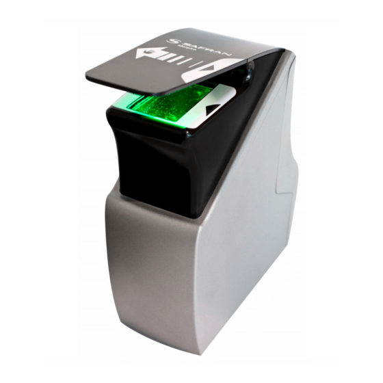
OEM – Installation guide MorphoWave Section 2 :General Description MorphoWave Desktop box opening © MorphoWave Desktop (or previously called Finger On The Fly ) is a biometric sensor providing an innovative and effective solution for performing very fast acquisitions or 4 fingerprints without any contact. -
Page 25: Morphowave Tm Desktop Technical Description
OEM – Installation guide MorphoWave Section 2 : General Description MorphoWave Desktop technical description Hardware Features © ® Model type MorphoWave Desktop (previously Finger On The Fly Capture type Hand swipe through the active volume without contact Capture capacity per Up to 4 fingers swipe motion Max hand speed... - Page 26 OEM – Installation guide MorphoWave Section 2 :General Description The external power supply of MorphoWave Desktop is provided with the product. Specifications are: NB : The external power supply is provided with two AC wires for the US and Europe market.
-
Page 27: Pc Wave Intel Core I7 Box Opening
OEM – Installation guide MorphoWave Section 2 : General Description PC Wave Intel Core i7 box opening The PC Wave provided with MorphoWave OEM is a specific setup preconfigured and installed with Morpho software. This configuration is powered with a high end Intel i7 processor to ensure optimal performances for access control application. -
Page 28: Ethernet Switch Wave
OEM – Installation guide MorphoWave Section 2 :General Description Ethernet Switch Wave The Ethernet Switch Wave provided with MorphoWave OEM has a specific configuration inside loaded by Morpho facility. This configuration will ensure an isolated and secured communication between MorphoAccess Sigma and the PC from external network. -
Page 29: Section 3 : Installation Procedure
OEM – Installation guide MorphoWave Section 3 : Installation Procedure Section 3 : Installation Procedure 2015_2000009096 V4 This document and the information therein are the property of Morpho. They must not be copied or communicated to a third party without the prior written authorization of Morpho May 2017... -
Page 30: Morphoaccess Sigma Wave Installation
OEM – Installation guide MorphoWave Section 3 :Installation Procedure MorphoAccess Sigma Wave installation Before proceeding to the installation Make sure that you have all the components described in “Components of the initial package” section at your disposal. Remove the wall plate. Keep this element at hand. ... -
Page 31: Installation
OEM – Installation guide MorphoWave Section 3 : Installation Procedure Installation Required tools (not supplied) Four (4) raw plugs + four (4) ø 3.5mm max and length 30mm screws. One (1) screwdriver adapted to screws above. One (1) Drill (with a drill bit diameter adapted to raw plugs above). ... -
Page 32: Figure 7: Face Camera Viewing Angle
OEM – Installation guide MorphoWave Section 3 :Installation Procedure Step by step procedure Figure 7: Face camera viewing angle The recommended height for fixing of the terminal is 1.40m (camera height). For an optimal use the terminal must be installed in an area where the lighting conditions are controlled. -
Page 33: Figure 8: Drilling Template
OEM – Installation guide MorphoWave Section 3 : Installation Procedure Drilling the mounting holes 21mm 59mm 40mm min 88mm Figure 8: Drilling template If not present, drill in the wall a hole with a diameter of 67mm (see Figure 8: Drilling template. -
Page 34: Figure 9: Wall Plate Preparation For Water Tightness
OEM – Installation guide MorphoWave Section 3 :Installation Procedure Preparing wall plate IP65 Figure 9: Wall plate preparation for water tightness Create a silicone bead all along the notch. The silicone bead shall be reduced to avoid overflow on the upper part of the wall plate (risk to prevent product mounting). Fixing Be sure that a sufficient space is reserved in the wall for the passage of cables, in particular for Ethernet. -
Page 35: Figure 11: Cabling Preparation
OEM – Installation guide MorphoWave Section 3 : Installation Procedure Cabling Cable for wiring shall be AWG 20 to 24, length shall be 12 cm to 15 cm (stripped on 0,6mm). Figure 11: Cabling preparation Prefer rigid cable to flexible cable (easier to connect) Connection details: Characteristics Conductor cross section solid or stranded... -
Page 36: Wiring Overview
OEM – Installation guide MorphoWave Section 3 :Installation Procedure Wiring overview Before proceeding, make sure that the person in charge of installation and connections is properly connected to earth, in order to prevent Electrostatic Discharges (ESD). In case of more than two digital signals use, digital grounds shall all be wired together outside the product. -
Page 37: Power Supply
OEM – Installation guide MorphoWave Section 3 : Installation Procedure Figure 13: Cabling layout To connect wire to block connector, insert cable in the round hole of the connector. To remove wire, insert a flat screw driver (0.4x2.0max) in the rectangular hole of the connector and pull the corresponding wire. -
Page 38: Figure 14: Power Supply Wiring
OEM – Installation guide MorphoWave Section 3 :Installation Procedure External Power supply Figure 14: Power supply wiring Power Supply 12V Positive 12 Volts, power supply Power ground Ground power supply External power supply Must comply with CEE/IEC EN60950 standard. ... - Page 39 OEM – Installation guide MorphoWave Section 3 : Installation Procedure POE (Power Over Ethernet) MorphoAccess Sigma terminal's power supply can also be provided by the Ethernet using RJ45 connection (Power Over Ethernet mode - IEEE802.3af compliant). This mode is only available when the optional POE module is installed in the product. Only POE module delivered by Morpho (kit reference 293656945) may be installed in the terminal.
-
Page 40: Output Relay
OEM – Installation guide MorphoWave Section 3 :Installation Procedure Output Relay Figure 15: Output relay wiring Relay 1 Contact relay (normally open) Relay 2 Contact relay strip Nominal characteristics of relay Load characteristics: 2 A max @ 30 VDC (according to the safety extra low voltage requirements independently of the power supply), ... -
Page 41: Morphoaccess Sigma Wave Tamper Switch
OEM – Installation guide MorphoWave Section 3 : Installation Procedure MorphoAccess Sigma Wave Tamper Switch Figure 17: MorphoAccess Sigma Wave Tamper switch wiring Switch 1 Tamper switch contact Switch 2 Strip on tamper switch Operating principle for the switch Product installed on the wall plate: switch enabled (contact closed). -
Page 42: Wiegand Input Wiring
OEM – Installation guide MorphoWave Section 3 :Installation Procedure Operating principle for the Integrator Tamper Switch This tamper switch is for Integrator who wants to inform the MorphoAccess Sigma Wave when the Integrator mechanical box is tampered. When the contact state is changed from close to open, the MorphoAccess Sigma Wave executes all actions configured in case of tamper. -
Page 43: Figure 20: Wiegand Output Wiring
OEM – Installation guide MorphoWave Section 3 : Installation Procedure Figure 20: Wiegand output wiring Digital ground Ground for Wiegand (connect pin 5 or 6) Digital ground Ground for Wiegand (connect pin 5 or 6) D0_OUT Out Wiegand OUT D0 (5V TTL) D1_OUT Out Wiegand OUT D1 (5V TTL) Wiegand LED IN 1 (option) : panel... -
Page 44: Serial Port Wiring
OEM – Installation guide MorphoWave Section 3 :Installation Procedure The MorphoAccess Sigma Wave terminal uses the timeout of the wait for a low level on the on LED1 wire or LED2 wire as “access denied” answer. To minimize at most the waiting time of the user, the MorphoAccess Sigma Wave terminal timeout value, must be adjusted to a value a little bit higher than the maximal value of the controller response time. - Page 45 OEM – Installation guide MorphoWave Section 3 : Installation Procedure Data (Output type required: Open drain D0_IN or 5V+/-5%) Clock (Output type required: Open drain D1_IN or 5V+/-5%) Card present signal (if configured, only Digital Output 0 one selectable for Morpho Legacy) Digital Output 1 Card present signal (if configured) Digital Output 2...
-
Page 46: Figure 22: Serial Port Wiring - Dataclock
OEM – Installation guide MorphoWave Section 3 :Installation Procedure DataClock Output Figure 22: Serial port wiring – DataClock Digital ground Ground for Wiegand (connect pin 5 or 6) Digital ground Ground for Wiegand (connect pin 5 or 6) D0_OUT Data ( 5V TTL ) D1_OUT Clock ( 5V TTL ) RS485... -
Page 47: Gpio Wiring
OEM – Installation guide MorphoWave Section 3 : Installation Procedure RS422 Figure 24: Serial port wiring – RS422 Digital ground Ground (connect pin 5 or 6) Digital ground Ground(connect pin 5 or 6) RS422 RX- RS422 inverting Receive RS422 RX+ RS422 non inverting Receive RS422TX+ RS422 non inverting Transmit... -
Page 48: Ethernet Connection
OEM – Installation guide MorphoWave Section 3 :Installation Procedure Digital Output 2 Reserved for Integrator Tamper Switch Single Door Access Control (SDAC) implementation Push button / Motion sensor External GPI0 Power supply RLY1 Door strike GPI1 RLY2 GPO0 GPO1 Door contact Figure 26: SDAC wiring If door contact is not used, GPI1 and GPO1 shall be connected together... - Page 49 OEM – Installation guide MorphoWave Section 3 : Installation Procedure Connecting MorphoAccess Sigma Wave terminal with default Ethernet configuration Administrator must change the default Ethernet configuration before deploying terminal on site. This can be achieved by several ways as mention below. ...
-
Page 50: Battery
OEM – Installation guide MorphoWave Section 3 :Installation Procedure EIA / TIA T568B White White Orange Blue White blue Green White brown Brown Colors orange green EIA / TIA T568A White White White White White green White green White green White green Colors green green... -
Page 51: Morphowave Desktop Installation
OEM – Installation guide MorphoWave Section 3 : Installation Procedure MorphoWave Desktop installation Prior components wiring, the MorphoWave Desktop has to be prepared as following: To access the power supply and USB cable, remove the rear plastic cover with an M3 CHC screwdriver. -
Page 52: Morphowave Oem Wiring
OEM – Installation guide MorphoWave Section 3 :Installation Procedure MorphoWave OEM wiring At this stage all component have been prepared, it is time to connect devices together. Material required (not included): Ethernet cable : 3 (2 internal + 1 for network connectivity) Power supply or Power Over Ethernet for MorphoAccess Sigma Installation procedure ... - Page 53 OEM – Installation guide MorphoWave Section 3 : Installation Procedure Connect the power adaptor of the MorphoWave Desktop. Connect the power adaptor of the Ethernet switch on the rear side. Connect the power adaptor of the PC. ...
-
Page 54: Section 4 : First Boot
OEM – Installation guide MorphoWave Section 4 :First boot Section 4 : First boot This document and the information therein are the property of Morpho. 2015_2000009096 V4 They must not be copied or communicated to a third party without the prior written authorization of Morpho May 2017... -
Page 55: First Biometric Record And Identification
OEM – Installation guide MorphoWave Section 4 : First boot First biometric record and identification To confirm the correct setup, we suggest to perform the first biometric enrollment and identification on your MorphoWave OEM terminal in standalone setup (no connected to the network). Please follow instructions below: ... - Page 56 OEM – Installation guide MorphoWave Section 4 :First boot Click on users icons>add user. Enter user’s informations then click on capture hands menu. Click on Hand 1 to start capture. Select one hand and number of fingers to enroll (up to 4 and thumbs are not available). This document and the information therein are the property of Morpho.
- Page 57 OEM – Installation guide MorphoWave Section 4 : First boot Follow guidelines displayed on the screen, two waves are required to perform one successful record. Once the enrollment is successful, following screen will be displayed. Click on green cross bottom right to finish the enrollment.
- Page 58 OEM – Installation guide MorphoWave Section 4 :First boot Click on the green cross bottom right to save the user in local database. Then go back in the main menu. Click on the bottom left arrow to set MorphoWave in identification mode. Now the biometric sensor will be turned ON waiting for one hand to acquire and provide identification status.
-
Page 59: Default Passwords To Be Changed
OEM – Installation guide MorphoWave Section 4 : First boot Default passwords to be changed The MorphoAccess Sigma Wave terminal and PC have default passwords to ease first installation procedure but it is highly recommended to change them prior to deploy the system on the field. -
Page 60: First Connection To An External Network
OEM – Installation guide MorphoWave Section 4 :First boot First connection to an external network Prior to connect the MorphoWave OEM on the external network by following MorphoManager User Guide, it is recommended to follow the “First biometric record and identification procedure” in a standalone mode (Ethernet switch not connected to the external network). -
Page 61: Modes For Controlling Access Rights
OEM – Installation guide MorphoWave Section 4 : First boot Modes for controlling access rights Introduction The MorphoWave OEM terminal offers several methods for controlling access rights: it needs to be configured in one of the following four modes: Identification mode, ... -
Page 62: Proxy Mode
OEM – Installation guide MorphoWave Section 4 :First boot Proxy mode The Proxy mode is an operating mode where the access control main application is located in a distant system. This is not a standalone mode like Identification and Authentication modes. It means that the terminal becomes a slave of the host system application. - Page 63 OEM – Installation guide MorphoWave Section 4 : First boot MorphoWave OEM terminal also has distant commands to retrieve polling buffer status and polling buffer data. How to Activate? External database mode can be activated through Webserver > Complete Configuration, by setting “ucc.enable_external_database” parameter to 1. Only an admin user can activate polling mode.
-
Page 64: Configuring The Terminal
OEM – Installation guide MorphoWave Section 4 :First boot Configuring the terminal MorphoWave OEM terminals are standalone biometric systems which offer advanced features for access control. To guarantee biometric performances it is required to load user’s templates acquired only with MorphoWave Desktop biometric sensor. -
Page 65: Anti-Tamper / Anti-Pulling Switches
OEM – Installation guide MorphoWave Section 4 : First boot Anti-tamper / anti-pulling switches Please refer also to “Tamper Switch” section. These switches are activated as soon as there is enough pressure applied on the terminal against the wall. They are deactivated as soon as this pressure is not big enough, e.g. -
Page 66: Section 5 : Accessories, Software Licenses And Pc Applications
OEM – Installation guide MorphoWave Section 5 :Accessories, Software Licenses and PC Applications Section 5 : Accessories, Software Licenses and PC Applications This document and the information therein are the property of Morpho. 2015_2000009096 V4 They must not be copied or communicated to a third party without the prior written authorization of Morpho May 2017... -
Page 67: Compatible Accessories, Licenses And Software
OEM – Installation guide MorphoWave Section 5 : Accessories, Software Licenses and PC Applications Compatible Accessories, Licenses and Software The following items can be ordered directly to Morpho or to an official distributor, so as to enjoy all the features of your MorphoWave OEM terminal: ... -
Page 68: Compatible Pc Applications
OEM – Installation guide MorphoWave Section 5 :Accessories, Software Licenses and PC Applications Compatible PC applications MorphoWave OEM terminals are fully compatible with: MorphoManager (version 6.1 or later) MorphoBioToolBox (version 2.3.1 or later) This document and the information therein are the property of Morpho. 2015_2000009096 V4 They must not be copied or communicated to a third party without the prior written authorization of Morpho May 2017... -
Page 69: Section 6 : Recommendations
OEM – Installation guide MorphoWave Section 6 : Recommendations Section 6 : Recommendations 2015_2000009096 V4 This document and the information therein are the property of Morpho. They must not be copied or communicated to a third party without the prior written authorization of Morpho May 2017... -
Page 70: Notice
OEM – Installation guide MorphoWave Section 6 :Recommendations Notice The manufacturer cannot be held responsible in case of non-compliance with the following recommendations or incorrect use of the terminal. General precautions Do not attempt to repair your terminal yourself. The manufacturer cannot be held responsible for any damage/accident that may result from attempts to repair components. -
Page 71: Cleaning Precautions
OEM – Installation guide MorphoWave Section 6 : Recommendations Cleaning precautions The use of a dry cloth is recommended to clean the terminal, especially the biometric sensor. Acid liquids, alcohol or abrasive materials are prohibited. Biometric sensor Clean the glass every day to optimize performances of the product especially when there is heavy dust deposit on the capture window. - Page 72 OEM – Installation guide MorphoWave Section 6 :Recommendations GPI/GPO MA SIGMA family 3 GPI 3 GPO (≈ 3 TTLOUT_H only) GPO current 5mA@5V limitation RELAY MA SIGMA family Relay pins NO / COM only available Driver 2 A @30V DC capabiity (Resistive load) *: NO: Normally open...
-
Page 73: Micro Sd Card
OEM – Installation guide MorphoWave Section 6 : Recommendations RS232 communication MA SIGMA family Not available Anti-theft/ Tamper switches MA SIGMA family Anti-theft switch Tamper switch Warning to a host if the product isn’t supplied Micro SD card The micro SD card is provided to ensure database storage. Lighting conditions for face detection In order to get good performance of the face detection, the following recommendations shall be respected:... -
Page 74: Biometric Acquisition Guidelines
OEM – Installation guide MorphoWave Section 6 :Recommendations Biometric acquisition guidelines MorphoWave Desktop is a biometric acquisition terminal which captures fingerprints by the applicant waving their hand through the active volume. The product can track and capture simultaneously up to 4 fingerprints at a maximum speed of 0.5m/s. To acquire fingerprints, the applicant waves his hand between the product glass and the top protective cap as shown in the figure below. -
Page 75: Capture Recommendations
OEM – Installation guide MorphoWave Section 6 : Recommendations Capture Recommendations Proper Use Below are several illustrations and guidelines on how to best use your new MorphoWave Desktop device. 2. Slightly spread apart your 1. Insert your hand flat, palm fingers down, from the front of the scanner... - Page 76 OEM – Installation guide MorphoWave Section 6 :Recommendations Improper Use The following illustrations show what NOT to do when using MorphoWave Desktop. 1. Do not place your hand upside down 1. Do not cross your fingers 2. Do not place your hand with 3.
- Page 77 OEM – Installation guide MorphoWave Section 6 : Recommendations 8. Do not place your hand on the 9. Do not place your hand too far up on the optical sensor edge of the optical sensor 10. Do not tilt your hand (left to 11.
- Page 78 OEM – Installation guide MorphoWave Section 6 :Recommendations This document and the information therein are the property of Morpho. 2015_2000009096 V4 They must not be copied or communicated to a third party without the prior written authorization of Morpho May 2017...
- Page 79 MorphoWave OEM– Installation Guide Annex 1 : Maintenance Annex 1 : Maintenance 2015_2000009096 V4 This document and the information therein are the property of Morpho. They must not be copied or communicated to a third party without the prior written authorization of Morpho May 2017...
-
Page 80: Maintenance Procedures
OEM – Installation guide MorphoWave Annex 1 : Maintenance Maintenance procedures Pairing procedure between MorphoAccess and PC The pairing process between MorphoAccess Sigma Wave and PC is automatically activated for security reason and data protection between both devices. It allows the MorphoAccess Sigma Wave and the PC to trust each other and share data encrypted for security reason. - Page 81 MorphoWave OEM– Installation Guide Annex 1 : Maintenance 2015_2000009096 V4 This document and the information therein are the property of Morpho. They must not be copied or communicated to a third party without the prior written authorization of Morpho May 2017...
-
Page 82: Unpairing Procedure Between Morphoaccess And Pc
OEM – Installation guide MorphoWave Annex 1 : Maintenance Unpairing procedure between MorphoAccess and PC This procedure is useful when a couple of MorphoAccess Sigma Wave and PC Wave are changed by new devices. This unpairing procedure explain you how to disassociate a couple of device. - Page 83 MorphoWave OEM– Installation Guide Annex 1 : Maintenance Click on Disassociate Sensor Then confirm. At this point of time, the MorphoAccess Sigma Wave has forgotten the PC connected. NB: When a unpaired PC running MorphoWave software will be connected to the MorphoAcce Sigma Wave, a new pairing process will be initiated.
-
Page 84: Morphowave Desktop Change Procedure
OEM – Installation guide MorphoWave Annex 1 : Maintenance MorphoWave Desktop change procedure To replace the MorphoWave Desktop sensor: Turn off the entire system (MorphoAccess Sigma Wave, MorphoWave Desktop, PC Wave, Ethernet switch). Unplug the USB 3.0 connector of the MorphoWave Desktop connected to the PC. -
Page 85: Ethernet Switch Change Procedure
MorphoWave OEM– Installation Guide Annex 1 : Maintenance Ethernet switch change procedure To replace the Ethernet switch: Turn off the entire system (MorphoAccess Sigma Wave, MorphoWave Desktop, PC,Ethernet switch). Unplug the Ethernet switch and replace it by the new one. ... -
Page 86: Debug Logs Activation
OEM – Installation guide MorphoWave Annex 1 : Maintenance Debug logs activation On Morpho request and to solve issue, it might be required to activate debug logs level for further investigation. Please follow instructions below to activate debugs logs: The activation can be performed through MorphoAccess Sigma Wave LCD screen: Go in administration menu. - Page 87 MorphoWave OEM– Installation Guide Annex 1 : Maintenance Select ON for Error log button. Select in Debug Level menu the Trace level. Validate your choice and in the administration menu select reboot button. A reboot is required to activate all logs. Logs retrieval on MorphoAccess Sigma Wave and PC: retrieve logs...
-
Page 88: Remote Pc Wave Connection For Maintenance
OEM – Installation guide MorphoWave Annex 1 : Maintenance Remote PC Wave connection for maintenance To operate a maintenance operation (software upgrade, debug log retrieval) it may asked by Morpho support to connect manually on the PC Wave of the MorphoWave OEM. - Page 89 MorphoWave OEM– Installation Guide Annex 1 : Maintenance In local area connection status, click on properties menu. Select Internet Protocol Version (TCP/IPv4). Then select properties. 2015_2000009096 V4 This document and the information therein are the property of Morpho. They must not be copied or communicated to a third party without the prior written authorization of Morpho May 2017...
- Page 90 OEM – Installation guide MorphoWave Annex 1 : Maintenance Set the IP address in static mode. Set IP address : 169.254.169.50 Subnet : 255.255.255.0 Then accept NB: The Ethernet board of the laptop may require deactivation then reactivation to apply new settings. In such case use the device manager control panel of windows and right click on the Ethernet chipset to activate and disable the unit.
- Page 91 MorphoWave OEM– Installation Guide Annex 1 : Maintenance After maintenance operation: On the laptop, it is recommended to change the IP address to DHCP after maintenance operation so as to recover the ability to reconnect on WiFi or LAN. 2015_2000009096 V4 This document and the information therein are the property of Morpho.
-
Page 92: Morphoaccess Sigma & Pc Internal Connection Checking
OEM – Installation guide MorphoWave Annex 1 : Maintenance MorphoAccess Sigma & PC internal connection checking From the PC Wave, it is possible to ping the MorphoAccess Sigma on the internal network so as to verify Ethernet link is fine between both devices. Please follow instructions below: Apply “Remote PC Wave connection for maintenance”... - Page 93 MorphoWave OEM– Installation Guide Annex 2 : Bibliography Annex 2 : Bibliography 2015_2000009096 V4 This document and the information therein are the property of Morpho. They must not be copied or communicated to a third party without the prior written authorization of Morpho May 2017...
-
Page 94: How To Get The Latest Versions Of Documents
OEM – Installation guide MorphoWave Annex 2 : Bibliography How to get the latest versions of documents The last version of the documents can be downloaded from our web site at the address below: www.biometric-terminals.com (Login and password required). To request a login, please send us an email to the address below: hotline.biometrics@morpho.com This document and the information therein are the property of Morpho. -
Page 95: Documents Concerning The Morphowave Oem® Terminal
MorphoWave OEM– Installation Guide Annex 2 : Bibliography Documents concerning the MorphoWave OEM® terminal Documents about installing the terminal MorphoWave™ OEM Installation Guide, Ref. 2015_0000009096 This document describes terminal physical mounting procedure, electrical interfaces and connection procedures. This document is in English. MorphoWave™... -
Page 96: Documents For The Developer
OEM – Installation guide MorphoWave Annex 2 : Bibliography Documents for the developer MorphoWave™ OEMHost System Interface, Ref. 2015_0000010428 This document describes the commands supported by the MorphoWave OEM® terminal. This document is in English. MorphoWave™ OEMCHM Thrift, Ref. 2015_0000010429 This document describes the format of messages sent by the terminal to a distant system. - Page 97 MorphoWave OEM– Installation Guide Annex 3 : Support & troubleshooting Annex 3 : Support & troubleshooting 2015_2000009096 V4 This document and the information therein are the property of Morpho. They must not be copied or communicated to a third party without the prior written authorization of Morpho May 2017...
-
Page 98: Troubleshooting
OEM – Installation guide MorphoWave Annex 3 : Support & troubleshooting Troubleshooting MorphoWave OEM does not boot at the first installation Several reasons may lead to such issue (wiring, pairing issue), please follow the procedure below until system is working. 1. -
Page 99: Morphowave Oem Displays Sensor Error Message
MorphoWave OEM– Installation Guide Annex 3 : Support & troubleshooting MorphoWave OEM displays sensor error message Following screen may appear if a connection issue is encountered between the PC and the MorphoWave Desktop: Please follow these steps to recover the system: Check the USB 3.0 connection between the MorphoWave Desktop and the PC. -
Page 100: Morphowave Oem Frost While Capturing Fingers During Local Enrollment
OEM – Installation guide MorphoWave Annex 3 : Support & troubleshooting MorphoWave OEM frost while capturing fingers during local enrollment In some very rare case, the local enrollment process may be frost while capturing fingers. The touchscreen does not react anymore when the user click on the screen and the biometric sensor is not responding when a hand is swipe inside. -
Page 101: Contacts
MorphoWave OEM– Installation Guide Annex 3 : Support & troubleshooting Contacts Customer service Morpho SAV Terminaux Biométriques Boulevard Lénine - BP428 76805 Saint Etienne du Rouvray FRANCE Phone: +33 2 35 64 53 52 Hotline Morpho Support Terminaux Biométriques 18, Chaussée Jules César 95520 Osny FRANCE hotline.biometrics@safrangroup.comPhone: + 33 1 30 20 30 40... - Page 102 MorphoWave - Installation Guide Annex 3 : Support & troubleshooting – R 2015_2000009096 V4 OCUMENT ORPHO EPRODUCTION ET DIVULGATION INTERDITES May 2017 May 2017...
Need help?
Do you have a question about the Morpho MorphoWave OEM and is the answer not in the manual?
Questions and answers