Table of Contents
Advertisement
Quick Links
Advertisement
Table of Contents

Related Manuals for Inspur ON5263M5


Summary of Contents for Inspur ON5263M5
- Page 1 Inspur Server User Manual ON5263M5...
- Page 2 Images provided herein are for reference only and may contain information or features that do not apply to your purchased model. Inspur shall not be liable for technical or editorial errors or omissions contained in this manual.
- Page 3 Please install the product-compatible operating system and use the driver provided by Inspur. If you use an incompatible operating system or non-Inspur driver, it may cause compatibility issues and affect the normal use of the product, Inspur will not assume any responsibility or liability.
-
Page 4: Table Of Contents
Table of Contents 1. Safety Instructions ................1 2. Product Specification ................5 Introduction ......................5 Specification ......................6 3. Product Overview ................7 Front View ......................7 Rear View ........................8 Motherboard View ....................9 Exploded Diagram ....................10 4. Getting Started..................11 Package Contents ....................11 Power On/Off .......................11 Pre-disassembly Instructions ................11 Disassembly/Reassembly Process ................12... - Page 5 6. BIOS Settings ..................22 Basic Operations ....................22 6.1.1 System Information ..................24 6.1.2 CPU Information ....................24 6.1.3 Memory Information ..................24 6.1.4 UEFI/Legacy Mode ....................25 6.1.5 RAID Volume Configuration ................25 6.1.6 BMC Network Configuration ................33 BIOS Setup Menu ....................37 6.2.1 Main ........................37 6.2.2 Advanced ......................38 6.2.2.1 Trusted Computing ...................39...
- Page 6 6.2.5.4 View FRU information ................78 6.2.6 Security ......................78 6.2.7 Boot ........................79 6.2.8 Save & Exit ......................80 Firmware Update ....................81 6.3.1 UEFI Shell ......................81 6.3.2 AMI Flash Utility ....................82 7. BMC Settings ..................84 Introduction ......................84 Software Interfaces ....................85 7.2.1 IPMI 2.0 ......................85 7.2.1.1 Channel ID Assignment for Each Interface ..........85 7.2.1.2...
- Page 7 7.4.2 BIOS Setup Options..................110 7.4.3 FRU Information .................... 111 7.4.4 History Record ....................111 Remote Control ....................113 7.5.1 Console Redirection (KVM) ................113 7.5.1.1 HTML5 KVM ................... 113 7.5.1.2 Java KVM ....................114 7.5.2 Locate Server ....................114 7.5.3 Remote Session Settings ................
- Page 8 7.9.2 BMC Recovery ....................130 7.9.3 Screen Capture ....................131 7.9.4 HOST POST Code .................... 131 7.9.5 BMC Watchdog for System ................131 7.10 Administration ....................132 7.10.1 User Management ..................132 7.10.1.1 User Privileges ..................134 7.10.2 Security ...................... 136 7.10.3 BMC Dual Image Configuration ..............
- Page 9 Battery Replacement Notice ................152 Electrostatic Discharge ..............153 11.1 Preventing Electrostatic Discharge ..............153 11.2 Grounding Methods to Prevent Electrostatic Discharge ........153 Warranty ..................154 12.1 Warranty Service ....................154 12.2 Inspur Service SLA ....................155 12.3 Warranty Exclusions ..................156 viii...
-
Page 10: Safety Instructions
For your safety, please do not attempt to remove the cover of the system to remove or replace any component without assistance provided by Inspur. Only service technicians trained by Inspur are authorized to remove the cover of the host, and to remove and replace internal components. - Page 11 In the event the following, please unplug the power line plug from the power socket and contact Inspur’s customer service department: The power cables, extension cables or power plugs are damaged. The products get so wet.
- Page 12 Close the host cover, reconnect the system to the power socket, and then power on. In case of operation failure or other abnormal situations, please contact Inspur and get technical support. Pay attention to the position of system cables and power cables-avoid placing wires in high foot traffic locations.
- Page 13 Switch the system power supply off and disconnect the cables, including all connections of the system. When disconnecting the cables, please hold the connector of the cables and slowly pull the plugs out. Never pull on the cables. The products need to completely cool down before dismounting the host cover or touching the internal components.
-
Page 14: Product Specification
512GB to handle versatile workloads among current datacenters. ON5263M5 has one (1) SATA/PCIE M.2, two (2) PCIe expansion slots, and one (1) OCP 2.0 slot at the front side, providing the ultimate flexibility for scale-out solutions. With modularized design, users can swap the selected front I/O modules to fulfill hardware requirements according to the multiple applications. -
Page 15: Specification
Specification Processor Intel® Xeon Scalable processor, TDP up to 165W Chipset Intel® C622 Memory Memory Type DDR4 RDIMM/LRDIMM Memory Slot Qty. Total Memory Capacity Supports up to 512GB (32GB per memory module) Port and Connector Two USB 3.0 ports (front side) One VGA port (front side) Mgmt One RJ45 IPMI port (front side) -
Page 16: Product Overview
3. Product Overview Front View Item UID Button with LED Power Button Thumb Screw (for Cubby) OCP Connector (x2) VGA Port USB 3.0 Port (x2) IPMI Port PCIe Riser-Card Module Product Overview... -
Page 17: Rear View
Rear View Item Fan Module (x2) Power Connector Product Overview... -
Page 18: Motherboard View
Motherboard View CPU0 CPU1 Item Item Fan Connector OCP Slot B Fan Connector VGA Port Power Connector USB 3.0 Port (x2) IPMI Port Power Button M.2 Card Slot UID Button PCIe Riser Slot OCP Slot A M.2 Card Snap Clip OCP Slot C Product Overview... -
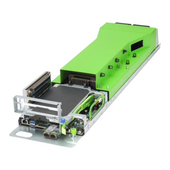
Page 19: Exploded Diagram
Exploded Diagram The following illustration shows the major components in the server. Item Air Baffle 8056 Fan Module (x2) DIMM Module (x16) M.2 Card Base with Motherboard OCP Card PCIe Card PCIe Riser Module Product Overview... -
Page 20: Getting Started
4. Getting Started Package Contents Unpack the server shipping carton and locate the materials and documentation necessary for installing the server. All the rack installation guide necessary for installing the server into the rack is included with the rack or the server. The contents of the server shipping carton include: Cubby •... -
Page 21: Disassembly/Reassembly Process
Do the following prior to starting any the installation or maintenance procedure. 1. Shut-down the server. 2. Remove all cables from the system. 3. Remove the node server from the rack. For more information on removing the node server, see Open Rack Server Installation Guide. - Page 22 2. Once the locking tabs are released from the server, remove the air baffle. 3. Follow the preceding steps to install the air baffle. NOTE: Make sure that both locking tabs are firmly secured on the server base when installing the air baffle. Getting Started...
-
Page 23: Fan Module Replacement
4.4.2 Fan Module Replacement 1. Remove the air baffle (Refer to Air Baffle Replacement). 2. Disconnect the fan cable from the motherboard connector. 3. Lift up and remove the fan module. 4. Follow the preceding steps to install the fan module. 4.4.3 DIMM Replacement WARNING: Always wear an electrostatic-discharge strap or gloves when removing or... - Page 24 4. Gently lift and remove the DIMM from the slot. 5. Install the DIMM in the order of DIMM population sequence (see the DIMM population sequence). Align the golden key of the DIMM with the receptive point on the slot. 6.
-
Page 25: Pcie Riser-Card Assembly Replacement
For dual CPUs, CPU0 DIMM population follows the screen printed sequence: • CPU0_C0D0, CPU0_C1D0, CPU0_C2D0…; CPU1 DIMM population follows the screen printed sequence: CPU1_C0D0, CPU1_C1D0, CPU1_C2D0. 4.4.4 PCIe Riser-Card Assembly Replacement Loosen the screw securing the PCIe riser-card assembly to the motherboard. Lift up and remove the PCIe riser-card assembly from the motherboard connector. -
Page 26: Ssd Replacement
Remove the two screws securing the PCIe card in place. Remove the PCIe card from the PCIe riser module. Follow the preceding steps to install the PCIe riser-card assembly. NOTE: Make sure that the PCIe riser-card assembly is firmly connected to the motherboard connector before tightening the screw to secure the PCIe riser-card assembly in place. - Page 27 3. Remove the M.2 SSD from the motherboard connector. 4. Follow the preceding steps to install the M.2 SSD. NOTE: Make sure that the snap clip is fully engage with the notch on the SSD. If the snap clip is not in the fully-closed position, the SSD has not been correctly installed. Press the snap clip firmly into the notch again until the SDD is fully secured in place.
-
Page 28: Setup
• of another rack or row of racks. Inspur Servers draw in cool air through the front door and expel warm air through the rear door. Therefore, the front and rear doors of the rack must be adequately ventilated to allow ambient room air to enter the cabinet, and the rear door must be adequately ventilated to allow the warm air to flow out from the cabinet. -
Page 29: Temperature
Any installation procedures must comply with local and regional electrical regulations governing the installation of information technology equipment by licensed electricians. Inspur Servers are designed to operate in installations covered by NFPA 70, 1999 Edition (National Electric Code) and NFPA-75, 1992 (code for Protection of Electronic Computer/ Data Processing Equipment). -
Page 30: Downloading The Drivers
Because of the high ground-leakage currents associated with multiple servers connected to the same power source, Inspur recommends the use of a PDU that is either permanently wired to the building’s branch circuit or includes a non-detachable cord that is wired to an industrial-style plug. -
Page 31: Bios Settings
CPU/memory initialization, detection of input and output devices and bootable devices to finally boot the operating system. The BIOS development of Inspur ON5263M5 is based on AMI Codebase, supporting Legacy and UEFI operating environments with in-band and out-of-band configurations and its flexibility and scalability is to meet various customized needs. - Page 32 When “Entering Setup …” appears in the lower right corner of the screen, the system enters to the BIOS Main Menu. In the BIOS Setup Menu, you can use the arrow keys to navigate through the BIOS menu and item, press the Enter key to enter the submenus. Other hotkeys function:...
-
Page 33: System Information
NOTE: Options grayed-out are not available. Options with symbol “ ” have a sub-menu. 6.1.1 System Information To view the system information, login to the BIOS Setup Menu and select “Main”. The Main menu displays the current system information, including BIOS/BMC/ME version, CPU/PCH SKU/RC version, memory and other information. -
Page 34: Uefi/Legacy Mode
Option ROM execution also need to set to [UEFI Mode] or [Legacy Mode]. The default setting of Boot Mode for Inspur ON5263M5 server is [UEFI Mode]. The advantages of UEFI mode are, it supports boot from the GPT disk, supports IPv6/IPv4 PXE boot, and provides UEFI Shell environment. - Page 35 To create a RAID volume under UEFI Mode: NOTE: This action is available when SATA Controller is set to [Enabled] and SATA Mode Options is set to [RAID]. 1. Login to the BIOS Setup Menu. 2. Select “Chipset → PCH SATA Configuration/PCH sSATA Configuration → SATA Mode Options”...
- Page 36 7. Using the following instructions in Table 6-2 to create the RAID Volume. Table 6-2 Creating a RAID Volume in UEFI Mode Parameter Description Name Enter a volume name less than 16 characters without containing any special characters. RAID Level Select the RAID volume level.
- Page 37 To delete a RAID Volume under UEFI Mode: 1. After creating a RAID Volume successfully, the RAID Volume information will appear on “Advanced →Intel(R) VROC SATA Controller” menu. Press Enter to show the detailed information 2. .Press Enter to delete the RAID Volume. 3.
- Page 38 To Create a RAID Volume under Legacy Mode: 1. Login to the BIOS Setup Menu, select “Advanced → CSM Configuration → Boot Mode”, and press +/- to change the item to [Legacy]. 2. Press F10 to save & exit the BIOS Setup. The system will reboot automatically. 3.
- Page 39 5. Using the following instructions in Table 6-4 to create a RAID Volume, and press Create Volume. Table 6-4 Creating a RAID Volume in Legacy Mode Parameter Description Name Enter a volume name less than 16 characters without containing any special characters. RAID Level Select the RAID volume level.
- Page 40 To delete a RAID Volume under Legacy Mode: 1. After creating a RAID Volume successfully, the RAID Volume information will appear on SATA RAID configuration interface. Select Delete RAID Volume and press Enter. 2. Press Del to delete the selected RAID Volume. 3.
- Page 41 To mark the HDD Disks to spare HDDs under Legacy Mode: 1. Use the <↑> or <↓> keys to select Mark Disks as Spare and press Enter. 2. The non-RAID HDDs will be displayed on the screen. Use the space key to select the HDD to be marked as spare, and press Enter.
-
Page 42: Bmc Network Configuration
6.1.6 Configuring the BMC Network To view the current configuration of BMC IPv4 or BMC IPv6 network: 1. Login to the BIOS Setup Menu. 2. Select “Server Mgmt → BMC Network Configuration BMC → IPv4 Network Configuration/BMC IPv6 Network Configuration”. Table 6-5 BMC Network Configuration Parameter... - Page 43 To configure the BMC Static network parameters: 1. Set the Get BMC Sharelink Parameters or Get BMC Dedicated Parameters to [Manual]. 2. Set the Configuration Address Source to [Static]. The “Set Static BMC IP Address Source Success!!” message appears. Press Enter to continue. 3.
- Page 44 to the Station IP address. This setting only changes the IP address in BIOS Setup interface, and does not notify BMC to change the IP settings. 5. Repeat step 3 and step 4 (on how to change the setting for Station IP address) to change the settings for Subnet mask, Station MAC address and Router IP address.
- Page 45 3. Wait for 30 seconds, press Enter when the “Get Dynamic BMC Dhcp Sucess!!” appears. 4. The BMC network parameters (Station IP address, Subnet mask, Station MAC address, and Router IP address) will be set dynamically. BIOS Settings...
-
Page 46: Bios Setup Menu
NOTE: Make sure that the BMC management port is connected to the network when • configuring to the [Manual] options. The options that take effect immediately are implemented by the Callback • function. Callback function is only activated when the options in the BIOS Setup are changed. -
Page 47: Advanced
Parameter Description Build Date The date and time when the BIOS Setup was created BMC Firmware Version BMC FW version information ME Firmware Version ME FW version information Access Level Current access level CPU Type Current CPU type CPU Current Speed Current CPU speed PCH SKU Current PCH SKU version... -
Page 48: Trusted Computing
6.2.2.1 Trusted Computing Enable or disable BIOS support for security device. Table 6-7 Advanced > Trusted Computing Parameter Description Default Setting / Format Security Device Security device support settings. Enabled Support (TPM) Options: Enabled/Disabled. NOTE: BIOS supports TPM TCG version 1.2/2.0. -
Page 49: Super Io Configuration
6.2.2.2 Super IO Configuration Set the super I/O chip information. Table 6-8 Advanced > Super IO Configuration Parameter Description Serial Port 0 Configuration Press <Enter> for configuration of advanced items. Serial Port 1 Configuration Press <Enter> for configuration of advanced items. Serial Port 0/1 Configuration enables/disables the Serial Port (COM). -
Page 50: Serial Port Console Redirection
Table 6-9 Advanced > Super IO Configuration > Serial Port 0/1 Configuration Parameter Description Default Setting / Format Serial Port Enable/disable the Serial Port (COM). Enabled Options: Enabled/Disabled Device Settings Display the Serial Port 1/2 device settings Change Settings Select an optimal setting for super IO device. Auto Options: •... - Page 51 Parameter Description Default Setting / Format NOTE: This item is only available when Console Redirection Com0/Console Redirection Com1 is set to [Enabled]. When the Console Redirection Settings is set to [Enabled], the Console Redirection Settings menu will be opened. Table 6-11 Advanced >...
-
Page 52: Pci Subsystem Settings
Parameter Description Default Setting / Format Flow Control Flow control can prevent data loss from None buffer overflow. When sending data, if the receiving buffers are full, a 'stop' signal can be sent to stop the data flow. Once the buffers are empty, a 'start' signal can be sent to re-start the flow. -
Page 53: Csm Configuration
Table 6-12 Advanced > PCI Subsystem Settings Parameter Description Default Setting / Format Above 4G Decoding Enable/Disable 64-bit capable Devices to be Enabled decoded in Above 4G Address Space (Only if System Supports 64 bit PCI Decoding) Options: Enabled/Disabled SR-IOV Support If the system has SR-IOV capable PCIe Enabled devices, this item Enable/Disable Single Root... - Page 54 Parameter Description Default Setting / Format Options: Upon Request/Always NOTE: This item is only available when CSM Support is set to [Enabled]. INT19 Trap Response Configure BIOS reaction on INT19 trapping by Immediate Option ROM. When set to Immediate, the system executes the trap right away.
-
Page 55: Onboard Lan Configuration
6.2.2.6 Onboard LAN Configuration Set the Onboard network card Configuration Table 6-14 Advanced > Onboard LAN Configuration Parameter Description Default Setting / Format Onboard PHY Card Enable/disable the Onboard PHY card. Enabled Control Options: Enabled/Disabled PHY NIC MAC Address Display the PHY NIC1/NIC2 MAC address NIC PXE ROM Enable/disable the NIC PXE ROM feature. -
Page 56: Network Stack Configuration
6.2.2.8 Network Stack Configuration Set the UEFI Network stack configuration. Table 6-15 Advanced > Network Stack Configuration Parameter Description Default Setting / Format Network Stack Enable/Disable the UEFI network stack. Enabled Options: Enabled/Disabled NOTE: When set to [Enabled], the following items are configurable. Ipv4 PXE Support Enable/Disable the Ipv4 PXE feature. -
Page 57: Iscsi Configuration
Press Enter to specify the iSCSI initiator name in iSCSI Qualified Name (iqn) format, for example: iqn.2019-07.com.inspur.000000. Add an Attempt Submenu BIOS Settings... - Page 58 Table 6-16 Advanced > Network Stack Configuration > iSCSI Configuration > Add an Attempt Parameter Description Default Setting / Format iSCSI Mode Enabled for MPIO. Disabled Options: Enabled/Disabled Internet Protocol This item is specific to IPv6. Options: IP4/IP6/Autoconfigure Connection Retry The minimum value is 0 and the maximum is Count 16.
- Page 59 Delete Attempts Submenu Delete one or more attempts by setting the item to [Enabled]. Change Attempt Order Submenu Change the order of Attempts using +/- keys. Use arrow keys to select the attempt then press +/- to move the attempt up/down in the attempt order list. BIOS Settings...
-
Page 60: Chipset
6.2.3 Chipset WARNING: Setting items on this menu to incorrect values may cause system to malfunction. The Chipset menu allows the user to configure the function and runtime error logging settings of PCH SATA/sSATA USB, and ME devices. To access the submenu item, press the Enter key. -
Page 61: Usb Configuration
NOTE: The SATA/sSATA port number displayed on the BIOS Chipset menu may vary depending on the actual product. Table 6-16 Chipset > PCH SATA/sSATA Configuration Parameter Description Default Setting / Format SATA Controller Enable/disable the SATA controller. Enabled Options: Enabled/Disabled SATA Mode Options When set to [AHCI], the RAID functions will AHCI... -
Page 62: Miscellaneous Configuration
Table 6-17 Chipset > USB Configuration Parameter Description Default Setting / Format XHCI USB3.0 Port Enable/disable the XHCI USB3.0 port Disabled Capability capability. Options: Enabled/Disabled USB * Enable/disable the onboard USB ports. Enabled Options: Enabled/Disabled USB Port Connected to Enable/disable the USB port connected to SD Disabled SD Card card. -
Page 63: Server Me Configuration
Parameter Description Default Setting / Format Options: 1GB/2MB VGA Priority Set the VGA device priority. Onboard Device Options: Onboard Device/Offboard Device 6.2.3.4 Server ME Configuration Display and set the server ME information. 6.2.3.5 Runtime Error Logging Set the system error logs. BIOS Settings... -
Page 64: Processor
6.2.4 Processor The Processor menu allows the user to configure the processor and memory information. To access the submenu item, press the Enter key. 6.2.4.1 Processor Configuration Configure the system processor settings. BIOS Settings... - Page 65 Table 6-19 Processor > Processor Configuration Parameter Description Default Setting / Format Active Cores Input the number of CPU cores you want to enable. In the Help information area, it will display the effective values you can set and the maximum number of physical cores according to the current CPU usage.
-
Page 66: Common Configuration
Parameter Description Default Setting / Format DCU Streamer Prefetcher the CPU data to shorten the data Prefetcher reading time Enabled Options: Enabled/Disabled. DCU IP Prefetcher Judge whether there is data to prefetch in Enabled order to shorten the data reading time. Options: Enabled/Disabled LLC Prefetcher Enable/disable all threads LLC. -
Page 67: Upi Configuration
Parameter Description Default Setting / Format Options: 56T/40T/24T/16T/4T/1T MMIO High Granularity MMIO high granularity size settings. 1024G Size Options: 1G/4G/16G/64G/256G/1024G Numa Allow a “NUMA Aware” OS to optimize which Enabled processor threads are used by processes can benefit by having the best access to those resources. -
Page 68: Memory Configuration
Parameter Description Default Setting / Format Link L0p Enable Link power-saving mode setting. Disabled Options: Enabled/Disabled Link L1 Enable In the case where the system is extremely Disabled idle, turn off the QPI Link. Options: Enabled/Disabled UPI Failover Support Enable/disable the UPI failover support. Enabled Options: Enabled/Disabled Sub NUMA Clustering... - Page 69 Table 6-21 Processor > Memory Configuration Parameter Description Default Setting / Format Enforce POR Configure the enforce POR. Options: POR/Disabled Memory Frequency Set the Memory frequency. Auto Options: Auto/1866/2133/2400/2666/2933 Data Scrambling for Enable/disable the NVMDIMM (DCPMM) Enabled NVMDIMM data scrambling. Options: Enabled/Disabled Data Scrambling for Enable/disable the DDR4 data scrambling.
- Page 70 Memory Map Submenu Table 6-21 Processor > Memory Configuration > Memory Map Parameter Description Default Setting / Format Volatile Memory Mode Volatile memory mode settings. Auto Options: 1LM/2LM/Auto AppDirect cache Enable caching for memory areas. Disabled Options: Auto/Enabled/Disabled eADR Support eADR support settings.
- Page 71 Parameter Description Default Setting / Format Below 4GB processor interleave. Options: Enabled/Disabled Memory RAS Configuration Submenu Table 6-22 Processor > Memory Configuration > Memory RAS Configuration Parameter Description Default Setting / Format Mirror Mode Mirror mode settings. Disabled Options: Disabled/Mirror Mode (1LM) Mirror TAD0 Mirror TAD0 mode settings.
-
Page 72: Iio Configuration
Parameter Description Default Setting / Format SDDC+1 settings. Disabled SDDC Plus One Options: Enabled/Disabled ADDDC sparing settings. Disabled ADDDC Sparing Options: Enabled/Disabled NGN Die sparing settings. Enabled Set NGN Die Sparing Options: Enabled/Disabled Patrol Scrub settings. Enabled Patrol Scrub Options: Enabled/Disabled Patrol Scrub interval settings, the unit is hour Patrol Scrub Interval and the range is 0-24. -
Page 73: Advanced Power Management Configuration
Parameter Description Default Setting / Format Intel VT for Directed Press <Enter> for configuration of advanced I/O (VT-d) items. Intel VMD Technology Press <Enter> for configuration of advanced items. PCIe Hot Plug PCIe hot plug settings. Enabled Options: Enabled/Disabled PCI-E ASPM Support PCIE ASPM support settings. - Page 74 Parameter Description Default Setting / Format Control items. Press <Enter> for configuration of advanced CPU C State Control items. Press <Enter> for configuration of advanced Package C State Control items. CPU-Advanced PM Press <Enter> for configuration of advanced Tuning items. Press <Enter>...
- Page 75 Parameter Description Default Setting / Format Config TDP TDP level settings. Normal Options: Normal/Level 1/Level 2 Boot performance BIOS boot performance mode settings. mode Options: Max Performance/Max Efficient/Set Performance by Intel Node Manager Turbo Mode Enable/disable the Intel(R) Turbo Boost Enabled Technology.
- Page 76 CPU C State Control Submenu Table 6-27 Processor > Advanced Power Management Configuration > CPU C State Control Parameter Description Default Setting / Format Monitor/Mwait Enable/disable the Monitor/Mwait instruction. Disabled Support Options: Enabled (two-way)/Disabled (four- way) Autonomous Core C- Enable/disable the autonomous core C-state. Disabled State Options: Enabled/Disabled...
- Page 77 Package C State Control Submenu Table 6-28 Processor > Advanced Power Management Configuration > Package C State Control Parameter Description Default Setting / Format Package C State Package C state settings. C0/C1 state Options: • C0/C1 state • C2 state •...
- Page 78 CPU-Advanced PM Tuning Submenu Set the CPU power-saving performance, with an Energy Perf BIAS submenu. Table 6-29 Processor > Advanced Power Management Configuration > CPU-Advanced PM Tuning > Energy Perf BIAS Parameter Description Default Setting / Format Power Performance Power performance tuning settings. BIOS Controls Tuning Options: OS Controls EPB/BIOS Controls EPB...
- Page 79 SOCKET RAPL Config Submenu Table 6-30 Processor > Advanced Power Management Configuration > Socket RAPL Config Parameter Description Default Setting / Format PL1 Power Limit PL1 power limit settings PL1 Time Window PL1 time window settings, the range is 0-56. PL2 Limit Enable/disable the PL2 limit function.
-
Page 80: Server Mgmt
6.2.5 Server Mgmt The Server Mgmt menu allows the user to configure the server additional features, including watchdog, BMC network configuration, BMC user settings, and system health information. Table 6-31 Server Mgmt Menu Parameter Description Default Setting / Format BMC Self Test Status BMC self-test status PASSED BMC Firmware Version... -
Page 81: Bmc Network Configuration
Parameter Description Default Setting / Format OS Wtd Timer Timeout Configure OS Watchdog Timer 10 minutes Options: 5 minutes/10 minutes/15 minutes/ 20 minutes NOTE: This item is only available when OS Watchdog Timer is set to [Enabled]. OS Wtd Timer policy Configure OS Watchdog Timer Policy. - Page 82 Table 6-32 Server Mgmt > BMC Network Configuration Parameter Description Default Setting / Format Enable/disable the Sharelink network Enabled Sharelink Network function. Options: Enabled/Disabled BMC IPv4 Network Press <Enter> for configuration of advanced Configuration items BMC IPv6 Network Press <Enter> for configuration of advanced Configuration items BMC IPv4 Network Configuration Submenu...
-
Page 83: Bmc User Settings
Table 6-33 Server Mgmt > BMC Network Configuration > BMC IPv4/IPv6 Network Configuration Parameter Description Default Setting / Format Get BMC Sharelink Set the method to get the BMC sharelink Do Nothing Parameters parameters. Options: Do Nothing/Auto/Manual Get BMC Dedicated Set the method to get the BMC dedicated Do Nothing Parameters... - Page 84 Add User Submenu Add a BMC user to the BMC user list. This action takes effect immediately. Table 6-34 Server Mgmt > BMC User Settings > Add User Parameter Description Default Setting / Format User Name Set the user name, up to 16 characters. ---- User Password Set the user password.
- Page 85 [Enabled]. Delete User Submenu Delete a BMC user from the BMC user list. This action takes effect immediately. Table 6-35 Server Mgmt > BMC User Settings > Delete User Parameter Description Default Setting / Format User Name Enter the user name you want to delete. ---- User Password Enter the password to confirm the deletion.
-
Page 86: Vlan Configuration
6.2.5.3 VLAN Configuration Configure the Virtual LAN (VLAN). Table 6-36 Server Mgmt > VLAN Configuration Parameter Description Default Setting / Format Sharelink/Dedicated Enable/disable BMC sharelink/dedicated Disabled VLAN Control VLAN function Options: Enabled/Disabled NOTE: To enable VLAN, it needs to set the BIOS Settings... -
Page 87: View Fru Information
Parameter Description Default Setting / Format VLAN ID first. Sharelink/Dedicated Set the BMC sharelink/dedicated VLAN ID, VLAN ID the range is 2-4094. NOTE: The setting takes effect immediately. Sharelink/Dedicated Set the BMC sharelink/dedicated VLAN VLAN Priority priority, the range is 1-7. NOTE: The setting takes effect immediately. -
Page 88: Boot
The Administrator Password and User Password are null by default, press Enter to set a new password. It must contain uppercase and lowercase letters, special characters and numbers, within 8-20 characters. 6.2.7 Boot The Boot menu allows the user to configure the boot mode, boot priority and boot procedure. -
Page 89: Save & Exit
Parameter Description Default Setting / Format Setup Prompt Timeout Set the time to wait for the Setup activate key. The maximum value is 65535 seconds. Bootup NumLock State Enable/disable the Bootup Numlock. Options: On/Off Boot Options Retry Enable/disable the Boot option retry feature. Enabled Options: Enabled/Disabled Add EFI Shell To Boot... -
Page 90: Firmware Update
There are two methods to update the firmware: UEFI Shell or under OS environment. 6.3.1 UEFI Shell To update the firmware with UEFI Shell: 1. When Inspur Logo appears on the screen during system booting, press F11 key to enter the Boot Menu. 2. Highlight UEFI: Built-in EFI Shell, and press Enter. -
Page 91: Ami Flash Utility
5. Execute the command to update the 32M ME+BIOS. NOTE: After the update is complete, power off the server, confirm that there is no residual electricity on the motherboard, and then power it on. 6.3.2 AMI Flash Utility To update the firmware in Linux: 1. - Page 92 5. Execute the command to update boht BIOS and ME: ./afulnx_64 BIOS.bin /b /p /n /x /k /l /me. NOTE: For Linux system, it needs to run the afulnx_64 tool as root. • After the update is complete, power off the server, confirm that there is •...
-
Page 93: Bmc Settings
7. BMC Settings This chapter describes the functional specifications of Inspur baseboard management controller (BMC) and its detailed information. Introduction Inspur Server Management System is a control unit for server management, and is compatible with the standard IPMI2.0 specification. The main functions of the Inspur Server Management System are: Remote control •... -
Page 94: Software Interfaces
Console Redirection (KVM) and Virtual Media • Serial Over Lan (SOL) • Diagnostic Log, System Event Log (SEL), Inspur Diagnostic Logs and One-key collection • BMC hardware watchdog timer, if the BMC does not respond within four minutes, • the fan will reach full speed. -
Page 95: System Interfaces
7.2.1.2 System Interfaces LPC interface is supported, and LPC provides hardware path for KCS messaging. 7.2.1.3 IPMB Interfaces BMC supports Intel NM4.0. Now, Secondary IPMB is used as the communication interface. 7.2.1.4 LAN interfaces Supports IPMI V2.0, compatible with V1.5 •... - Page 96 IPMI Device “Global” Command NetFn SUPPORT Broadcast ‘Get Device ID’ [1] 0x02 Cold Reset 0x03 Warm Reset 0x04 Get Self Test Results 0x05 Manufacturing Test On 0x06 Set ACPI Power State 0x07 Get ACPI Power State 0x08 Get Device GUID 0x09 Get NetFn Support 0x10...
- Page 97 IPMI Device “Global” Command NetFn SUPPORT Clear Message Flags 0x30 Get Message Flags 0x31 Enable Message Channel Receive 0x32 Get Message 0x33 Send Message 0x34 Read Event Message Buffer 0x35 Get BT Interface Capabilities 0x36 Get System GUID 0x37 Set System Info Parameters 0x58 Get System Info Parameters 0x59...
- Page 98 IPMI Device “Global” Command NetFn SUPPORT Deactivate Payload 0x49 Get Payload Activation Status 0x4A Get Payload Instance Info 0x4B Set User Payload Access 0x4C Get User Payload Access 0x4D Get Channel Payload Support 0x4E Get Channel Payload Version 0x4F Get Channel OEM Payload Info 0x50 Master Write-Read 0x52...
- Page 99 IPMI Device “Global” Command NetFn SUPPORT Get System Boot Options Chassis 0x09 Get POH Counter Chassis 0x0F Event Commands Set Event Receiver 0x00 Get Event Receiver 0x01 Platform Event (a.k.a. “Event 0x02 Message”) PEF and Alerting Commands Get PEF Capabilities 0x10 Arm PEF Postpone Timer 0x11...
- Page 100 IPMI Device “Global” Command NetFn SUPPORT Re-arm Sensor Events 0x2A Get Sensor Event Status 0x2B Get Sensor Reading 0x2D Set Sensor Type 0x2E Get Sensor Type 0x2F Set Sensor Reading And Event Status 0x30 FRU Device Commands Get FRU Inventory Area Info Storage 0x10 Read FRU Data...
- Page 101 IPMI Device “Global” Command NetFn SUPPORT Reserve SEL Storage 0x42 Get SEL Entry Storage 0x43 Add SEL Entry Storage 0x44 Partial Add SEL Entry Storage 0x45 Delete SEL Entry Storage 0x46 Clear SEL Storage 0x47 Get SEL Time Storage 0x48 Set SEL Time Storage 0x49...
- Page 102 IPMI Device “Global” Command NetFn SUPPORT Get PPP UDP Proxy Receive Data Transport 0x17 Serial/Modem Connection Active Transport 0x18 Callback Transport 0x19 Set User Callback Options Transport 0x1A Get User Callback Options Transport 0x1B Set Serial Routing Mux Transport 0x1C SOL Activating Transport 0x20...
-
Page 103: Web Gui
IPMI Device “Global” Command NetFn SUPPORT Send ICMB Connection ID Bridge 0x0C Discovery Commands (ICMB) PrepareForDiscovery Bridge 0x10 GetAddresses Bridge 0x11 SetDiscovered Bridge 0x12 GetChassisDeviceId Bridge 0x13 SetChassisDeviceId Bridge 0x14 Bridging Commands (ICMB) BridgeRequest Bridge 0x20 BridgeMessage Bridge 0x21 Event Commands (ICMB) GetEventCount Bridge 0x30... -
Page 104: Web Gui Login
Ubuntu 14.04.03 LTS x64 MAC OS X Firefox 43, Chrome 47+ Fedora 23 x64 On MAC Client: Safari CentOS 7 x64 7.2.2.1 Web GUI Login Step 1 Type “https://BMC_IP” in the browser address bar. NOTE: The port number is modifiable (For more information, see 7.7.2 Service Settings). -
Page 105: Web Gui Introduction
Step 2 In the WEB login page, enter the user name and password, click the “Login” button to enter the home page. If you forget your password, you can click “Forgot Password?” to get a new password by Email. Be sure to configure the Email address in advance in “User Administration” page and configure the SMTP server information in “SMTP”... - Page 106 Table 7-2 Features supported in Web GUI Menu Subdirectory Main content Auto Refresh Support Overview General System Running State Information BMC information and server information Quick Launch Tasks Active Session FW Version Information Recent System Event Logs Information System Info Device asset info and health state, include: Memory...
- Page 107 Menu Subdirectory Main content Auto Refresh Support Fan Speed Display fan speed and state; Switch to Control manually fan control BMC Settings BMC Network BMC Network Setting BMC DNS Setting Network Interface Bonding Network Link Services Supported service or protocol setting BMC time setting SMTP SMTP setting for email alert...
-
Page 108: Snmp
Menu Subdirectory Main content Auto Refresh Support Update BIOS FW Update NO Upgrade BIOS firmware Restore Factory Restore BMC settings to factory defaults Defaults 7.2.3 SNMP Simple Network Management Protocol (SNMP), consists of a set of standards for network management, including an application layer protocol, a database schema, and a set of data objects. -
Page 109: Smash-Lite Cli
7.2.4 Smash-Lite CLI 7.2.4.1 Command Line Login BMC supports Smash-Lite CLI, users can login to BMC via SSH and enter Smash-Lite CLI. After logging in, you can enter the command line interface. 7.2.4.2 Command Line Features Smash-Lite CLI supports ipconfig, sensor, fru, chassis, user, mc, fan, cpld, id, and diagnose commands. - Page 110 Get Sensor Information You can get a list of all sensor information using sensor commands. Get and Set FRU Information You can get and set the FRU information using fru commands. Get and Control Chassis Status You can get and control the system power status using chassis commands. BMC Settings...
- Page 111 Get, Add, and Delete Users You can access and edit (add or delete) the user list using user commands. Get BMC Versions and Reboot BMC You can get the BMC version information and reboot the BMC using mc commands Get and Set Fan Information You can get the fan information and setup the fan mode and fan level using fan commands.
-
Page 112: System Overview
Get ID You can get the UUID and SN information using id commands. 10. Fault Diagnosis You can execute the common tools and commands to check the BMC operating status using diagnostic commands. System Overview When log-in to the WEB GUI, the system overview page is displayed. It contains the server health information, management device information, server information, online user information, firmware version information, and a list of recent event logs. - Page 113 Item Description Current Power Status Power On Power Off UID Status UID LED On UID LED Off CPU Healthy state: Normal – All CPUs Normal Warning – One or more CPUx_Status warning Critical – One or more CPUx_Status critical Power Off Fan Healthy state: Normal –...
-
Page 114: Management Device (Bmc) Information And Server Information
7.3.2 Management Device (BMC) Information and Server information The general information also shows the BMC information and server information. 7.3.3 Quick Launch The quick launch tasks allows you to perform the shortcut operations. 7.3.4 Online User Information The active session shows the on-line user information about the information of the current-user logged in on the BMC WEB, including the user type, user name, user privilege, and IP address. -
Page 115: Recent Event Logs
Firmware Item Description Revision and Build Time BIOS Revision and Build Time Revision CPLD Revision 7.3.6 Recent Event Logs The recent system event log shows the recent event log information. Click "More" for more event logs. Information 7.4.1 System Information On the WEB GUI, go to the Information →... - Page 116 Item Description Critical Absent or PowerOff Processor Speed Processor speed Core Core number TDP(W) L1 Cache (KB) L1 Cache L2 Cache (KB) L2 Cache L3 Cache (KB) L3 Cache Click on the Memory tab to see the memory information. Click on the Device Inventory tab to see the device inventory information. BMC Settings...
- Page 117 Click on the Network tab to see the BMC and System adapter information. Click on the FAN tab to see the fan information. Item Description FANx_y, x denotes FAN or FAN group number, y denotes the FAN number in group. Present Present Absent...
- Page 118 Click on the Temperature tab to see the temperature information. Item Description Sensor Sensor name Normal Warning Status Critical State unavailable or current power is off Reading (°C) Temperature reading Low NRT (°C) Low Non Recoverable Threshold Low CT (°C) Low Critical Threshold Low NCT (°C) Low Non Critical Threshold...
-
Page 119: Bios Setup Options
Item Description Normal Status Warning Critical State unavailable or current power is off Reading (V) Voltage reading Low NRT (V) Low Non Recoverable Threshold Low CT (V) Low Critical Threshold Low NCT (V) Low Non Critical Threshold Up NCT (V) Up Non Critical Threshold Up CT (V) Up Critical Threshold... -
Page 120: Fru Information
Chassis part number: ** Chassis serial number: ** Board Information Board information area format version: * Manufacture date time: weekday/month/day/year Board manufacturer: Inspur Board product name: ***** Board serial number: ** Board part number: ** Product Information Product information area format version: *... - Page 121 On the WEB GUI, go to the Information →History Record. The history record page shows the system current power, CPU total power, total memory power and a specific period of peak power, average power, and cumulative power consumption. BMC Settings...
-
Page 122: Remote Control
Remote Control 7.5.1 Console Redirection (KVM) Remote KVM redirects the host system’s console to user’s PC by BMC. When the user logins in to BMC and open KVM, then host’s screen will be displayed in KVM application. User then can use PC’s keyboard and mouse to control the server. 7.5.1.1 HTML5 KVM BMC supports HTML5 KVM (for Google Chrome 58 and above, and Internet Explorer 11 and above). -
Page 123: Java Kvm
7.5.1.2 Java KVM BMC supports Java KVM. To enter the JRE environment , users should download and open JNLP (Java Application). The supported JRE version: jre-7u40 and above; and jre-8u45 and above. On the WEB GUI, go to the Remote Control →Console Redirection, and then click Launch KVM Java Viewer. -
Page 124: Remote Session Settings
7.5.3 Remote Session Settings On the WEB GUI, go to the Remote Control → Configure Remote Session to configure the remote session settings. KVM can be reconnected after network is disconnection. The retry count range is 1-20 (12 by default), and the retry time interval is 5-30 (10 second by default). - Page 125 On the WEB GUI, go to the Remote Control →Virtual Media Devices to configure the virtual media, including Virtual Media Setup and Virtual Media Instance. To enable/disable the local media support or remote media support, click the checkbox in the Virtual Media Setup tab. To emulate a SD Media on BMC as a USB device to the Host Server, click the SD Media Support checkbox in the Virtual Media Instance tab To enable/ disable the virtual USB devices visibility in the host server, click the Power Save...
-
Page 126: Mouse Mode Settings
User can also install the virtual media in KVM as shown below. 7.5.5 Mouse Mode Settings On the WEB GUI, go to the Remote Control → Mouse Mode Settings to configure the mouse mode. Host OS Client OS Windows 8 Windows 7 Windows Server Windows Server... -
Page 127: Power And Fan
Host OS Client OS Windows 8 Windows 7 Windows Server Windows Server 2012 2008 R2 RHEL 6.4 Absolute Absolute Absolute Absolute RHEL 7.0 Absolute Absolute Absolute Absolute Fedora10 Relative Relative Relative Relative Fedora11 Absolute Absolute Absolute Absolute Fedora12 Absolute Absolute Absolute Absolute Fedora14... -
Page 128: Fan Speed Control
Virtual Power Button: Power Restore Setting: 7.6.2 Fan Speed Control BMC supports the Manual Fan Control / Auto Fan Control function, and the fan module speed is controlled by the thermal algorithm. On the WEB GUI, go to the Power and Fan → Fan Speed Control to show the fan status The Auto Fan Control is the default setting. -
Page 129: Bmc Settings
BMC Settings BMC usually supports an LAN controller dedicated to BMC and a LAN controller shared for both BMC and the system. Maximum bandwidth: Dedicated NIC – 1000M, Shared NIC – 100M. • BMC network interface compatibly supports IPV4 and IPV6, supports DHCP or IP •... -
Page 130: Service Settings
2. DNS On the WEB GUI, go to the BMC Settings → BMC Network →DNS to configure the host, domain name and DNS. 3. Network Link On the WEB GUI, go to the BMC Settings → BMC Network → Network Link to configure the network connection for the available networks. -
Page 131: Ntp Settings
On the WEB GUI, go to the BMC Settings → Services to display the protocols and ports information. NOTE: Http/Https (WEB) Timeout: if there is no web request in Timeout, web session will be deleted, and new web request will not respond. If the web page has no auto update, it will be logged out when you switch pages or refresh the page after timeout. -
Page 132: Smtp Settings
7.7.4 SMTP Settings On the WEB GUI, go to the BMC Settings → SMPT Settings to configure the SMTP settings. 7.7.5 Alert Management BMC supports the SNMP Trap configuration. User can open trap receiver and set trap destination IP in BMC Web GUI. When BMC detects an event, BMC will send the event to the trap receiver. - Page 133 Step 1 On the WEB GUI, go to the BMC Settings → Alert Settings to setup the SNMP Trap protocol. Step 2 Select the sensor type or sensor name to setup the event filter. Step 3 Setup the alert type and destination. If SNMP is selected, the destination IP address should be set as well.
-
Page 134: Access Control
7.7.6 Access Control On the WEB GUI, go to the BMC Settings → Access Control to manage the entries for the IP address range and MAC address that run or block access to the BMC. User can add new entries or delete existing entries. 7.7.7 BIOS Boot Options BMC supports the BIOS boot options. -
Page 135: System Event Log
7.8.1 System Event Log BMC provides the system event log function, to record the IPMI sensors based on the event history. System event log outputs the following items and user can get the sensor event information by WEB or IPMI CMD. Support up to 3639 items. -
Page 136: Bmc System Audit Log
The specific configuration parameters of the system event log are shown in the following table: Parameter Description Filter Select event types, sensors, severity, and start and end dates for a filtered search. Action: You can use the filter options (event types, sensor types, sensor names, event severity levels, and time) to view specific events logged in the device. -
Page 137: Event Log Setting
On the WEB GUI, go to the Logs → BMC System Audit Log → BMC System Log to display the BMC system log. User can filter the audit logs by choosing the types (alarm, criticality, fault, notification, warning, debug, emergency, and information), start time and end time, and click the "Export Log"... -
Page 138: One-Key Collection Log
7.8.5 One-key Collection Log BMC supports the one-key log collection. On the WEB GUI, go to the Logs → One-Key Collect Log. Click on the One-Key Collect Log button to collect logs, it takes about 4-5 minutes. After the logs are collected, click on the Export Log button to export the logs, including the black box logs, alarm logs, audit logs, debug logs, etc. -
Page 139: Fault Diagnosis
Fault Diagnosis Diagnostic tool provides the ability of check and verification for BMC or Host system to check whether there is something out of function or something does not work correctly. 7.9.1 BMC Self-inspection Result On the WEB GUI, go to the Fault Diagnosis →BMC Self-inspection Result to displays the BMC self-inspection codes. -
Page 140: Screen Capture
7.9.3 Screen Capture BMC will record the screen when a server restarts or is shut down, and supports BSOD (Blue Screen of Death) screen capturing, server OS should be Windows 2012R2 and above. On the WEB GUI, go to the Fault Diagnosis → Capture Screen to to enable/disable the auto capture function. -
Page 141: Administration
7.10 Administration 7.10.1 User Management BMC supports IPMI, WEB, SSH, and SNMP users. BMC supports unified user management mechanism to manage IPMI, WEB and SSH users. Users created by IPMI or WEB will have IPMI, WEB as well as SSH user privileges, and can access Smash-Lit CLI via SSH. - Page 142 For BMC System Administrator: On the WEB GUI, go to the Administration → User Administration →System Administrator to manage the system administrator account. The system administrator can access BMC diagnose serial consoles, users can change passwords by IPMI CMD or WEB GUI. User name: sysadmin (Fixed, cannot be changed) Default password: superuser NOTE:...
-
Page 143: User Privileges
7.10.1.1 User Privileges User privileges includes 3 types: IMPI user privilege, WEB GUI user privilege, and Smash- Lite CLI user privilege. IPMI User Privileges BMC has two ways to receive IPMI CMD, out-band and in-band. Out-band mode means sending IPMI CMD to BMC by LAN, BMC will authenticate the •... - Page 144 Menu Subdirectory User Operator Administrator Access Control Read Only Read Only Read/Write BIOS Boot Options Read Only Read Only Read/Write Logs System Event Log Read Only Read Only Read/Write BMC System Audit Log Read Only Read Only Read/Write Event Log Setting Read Only Read Only Read/Write...
-
Page 145: Security
diagnose 7.10.2 Security LDAP Settings On the WEB GUI, go to the Administration → Security → LDAP Settings to enable and configure LDAP/E-Directory. AD Settings On the WEB GUI, go to the Administration → Security → AD Settings to enable and configure Active Directory. -
Page 146: Bmc Dual Image Configuration
7.10.3 BMC Dual Image Configuration Dual image means that BMC supports dual image in flash memory. When the main image fails to start, BMC will try to boot with another image. On the WEB GUI, go to the Administration →Dual Image configuration to display or modify the dual-image configuration. - Page 147 Step 1 On the WEB GUI, go to the Administration →BMC Firmware Update to change the image to be updated. The default setting is Both Images, meaning both images will be updated. Check the Preserve all configuration box to preserve the configuration, click on the Enter Preserve Configuration button to select items needed to be preserved, and click on the Enter Firmware Update Mode button to start the update process.
-
Page 148: Bios Fw Update
Step 3 Check the image uploaded version and current version, then click on the Proceed to update button to start the update process. Wait for about 15 minutes (both images), then the BMC flash is complete. 7.10.5 BIOS FW Update BMC supports BIOS firmware update via WEB GUI. - Page 149 After BIOS firmware update is finished, BIOS NVRAM will be cleared, all BIOS configuration will be reset to defaults. If BIOS and ME images are updated simultaneously, it is recommended that to power off the server completely. Step 1 On the WEB GUI, go to the Administration →BIOS Firmware Update, and then click Enter Firmware Update Mode to enter the update mode.
-
Page 150: Restore Factory Defaults
7.10.6 Restore Factory Defaults BMC supports the restore factory defaults via WEB GUI. On the WEB GUI, go to the Administration → Restore Factory Defaults to restore to the factory defaults. NOTE: The Update Policy Overwrite means the selected items will be overwritten to the default settings after clicking on the Restore Factory Defaults button or after upgrading BMC;... -
Page 151: Device State Monitor And Diagnostic
Item Preserved configuration Note included. User IPMI user Select IPMI option when this configuration is included. DCMI DCMI Select IPMI option when this configuration is included. Network BMC network SNMP SNMP KVM and Virtual Media Devices Authentication Authentication, including LADP and superuser Syslog Syslog Hostname... -
Page 152: Virtual Sensors
Button: An assertion event will be logged, when power button or reset button is • pressed. 7.11.1.2 Virtual Sensors BMC also reports various system state changes by maintaining virtual sensors that are not specifically tied to physical hardware. IPMI watchdog: BMC supports an IPMI watchdog sensor as a means to log SEL events •... -
Page 153: Cpu
7.11.2 CPU The following table shows the CPU health state. State Level Related model Present Info SDR/SEL Thermal Trip Critical SDR/SEL Processor Hot Critical SDR/SEL Error0 Warning Blackbox Error1 Warning Blackbox Error2 Critical Blackbox CPU VR Hot Critical Blackbox PCH Thermal Trip Critical Blackbox 7.11.3 Memory... - Page 154 Step 2 →User Administration configure email On the WEB GUI, go to the Administration address for the related users. Step 3 Setup the alert type and destination. If SNMP is selected, the destination IP address should be set as well. If Email is selected, the LAN Channel should be set to dedicated or shared network, then set the destination to a user configured email.
-
Page 155: Syslog
7.12.2 Syslog Syslog is used for sending the alarm events to remote sites. 7.13 BMC Self Recovery BMC self recovery provides the ability of automatic repair operations if necessary. 7.13.1 Hardware Watchdog Known fault scenarios: Kernel panic • System resources exhausted or error, system can’t create a new task, but the original •... -
Page 156: Sol And System Serial Log
7.15 SOL and System Serial Log Serial Over LAN (SOL) Serial Over LAN (SOL) redirects the system serial port to the remote network client. Users connect to the BMC on the local PC, open the serial port redirection function with the standard IPMI command (sol activate), view the system serial output, and enter the system serial port. - Page 157 System Serial Log BMC can record system serial information. The logs BIOS or OS sends to the serial port will be recorded to the BMC’s DDR, and keep up to 2M bytes of system serial logs. When more than 2M, log will loop to store, and the old log content will be deleted. When the system crashes or restarts, system serial log can be exported, and fault information can be used for fault diagnosis.
-
Page 158: Troubleshooting
8. Troubleshooting To access the troubleshooting resources, see the Inspur Information Library https://en.inspur.com/en/2494815/2498880/index.html Troubleshooting... -
Page 159: Battery Replacement
9. Battery Replacement If the server does not show the date and time correctly, you may need to replace the battery that provides power to the real-time clock. WARNING: The server contains an internal lithium manganese dioxide, a vanadium pentoxide, or an alkaline battery pack. A risk of fire and burns exists if the battery pack is not properly handled. -
Page 160: Regulatory Information
10. Regulatory Information 10.1 Regulatory Compliance Identification Numbers For the purpose of regulatory compliance certifications and identification, this product has been assigned a unique regulatory model number. The regulatory model number can be found on the product nameplate label, along with all required approval markings and information. -
Page 161: Battery Replacement Notice
Batteries, battery packs, and accumulators should not be disposed of together with the general household waste. To forward them to recycling or proper disposal, use the public collection system or return them to Inspur, an authorized Inspur Partner, or their agents. Regulatory Information... -
Page 162: Electrostatic Discharge
Use a portable field service kit with a folding static-dissipating work mat. • If you do not have any of the suggested equipment for proper grounding, have an authorized reseller install the part. For more information on static electricity or assistance with product installation, contact Inspur Customer Service. Electrostatic Discharge... -
Page 163: Warranty
12. Warranty Inspur warrants that all Inspur-branded hardware products shall be free from material malfunctioning and material defects under conditions of normal use for a period of three (3) years from the Date of Invoice. Service offerings may vary by geographic region. Please contact your Inspur representative to identify service levels and needs for your regions. -
Page 164: Inspur Service Sla
RMA number and return information that customer may use to return for RMA service. Inspur will ship out replacement part(s) within one (1) business day after receiving the defective part(s) and cover one-way shipment via ground. -
Page 165: Warranty Exclusions
• limit In no event will Inspur be liable for any direct loss of use, interruption of business, lost profits, lost data, or indirect, special, incidental or consequential damages of any kind regardless of the form of action, whether in contract, tort (including negligence), strict liability or otherwise, even if Inspur has been advised of the possibility of such damage, and whether or not any remedy provided should fail of its essential purpose.
Need help?
Do you have a question about the ON5263M5 and is the answer not in the manual?
Questions and answers