Table of Contents
Advertisement
Advertisement
Table of Contents

Related Manuals for Inspur NF5180M4


Summary of Contents for Inspur NF5180M4
- Page 1 INSPUR SERVER USER MANUAL NF5180M4 V1.0...
-
Page 2: Target Audience
Copyright Introduction Document version: V1.0 Date: 13 April. 2015 Document Introduction: The 1st formal issuance. Abstract The manual introduces issues closely related to maintenance such as specification, hardware operation, software configuration, service terms, fault diagnosis etc. of the server. Readers of this guide will be deemed to have abundant knowledge about the server product, and will not cause any personal injury or product damage during operation and maintenance, for sufficient trainings received by them. - Page 3 Warning: This manual introduces this server’s technical features and system installation and setup, which helps you to particularly understand and expediently use this server. ① Please do not disassemble the server’s components arbitrarily. Please do not extend configuration or connect other peripheral devices arbitrarily. If needed, please be sure to conduct it with our authorization and guidance.
-
Page 4: Table Of Contents
Table of Content 1 SAFETY INTRODUCTION ...................... 1 2 PRODUCT SPECIFICATION INTRODUCTION ..............6 2.1 Introduction ......................... 6 2.2 Features and Specification ....................7 2.3 Front Panel .......................... 9 2.4 Rear Panel ........................... 11 2.5 Mainboard Layout ....................... 12 2.6 Mainboard Jumper Introduction ..................14 3 BIOS CONFIGURATION ...................... - Page 5 5 HARDWARE MAINTENANCE ....................73 5.1 Tool Preparation ........................73 5.2 Parts Replacement ....................... 73 6 FREQUENT FAULTS, DIAGNOSIS AND TROUBLESHOOTING ........82 6.1 Frequent Faults ........................82 6.2 Diagnosis and Exclusion Instructions ................. 83 7 SPECIFICATIONS ........................86 7.1 USA FCC Statement ......................86 7.2 CE Statement of EU ......................
-
Page 6: Safety Introduction
Inspur; only maintenance technicians trained by Inspur have the right to disassemble the cover of the host, dismount and replace the internal components. - Page 7 Please place the system far away from the cooling plate and at the place with heat sources, and be sure not to block the air vents. Be sure not to scatter food or liquid in the system or on other components, and do not use the product in humid and dusty environment.
- Page 8 Close the cover of the host, re-connect the system to the power socket, and then start the equipment. In case of operation failure or abnormal situation, please contact Inspur and get technical support. Pay attention to the position of the system cables and power cables, wire them in places not to be stepped on or knocked down and ensure not to place other objectives on the cables.
- Page 9 When dismounting the internal components with the approval of Inspur, please pay attention to the following matters: Switch off the system power supply and disconnect the cables, including disconnecting any connection of the system.
- Page 10 Safety Introduction components or connection points on the plug-in cards. When taking the plug-in cards or components, you should grab the edges of the plug-in cards or components or their metal fixed supports. During the process of cabinet installation and application, please pay attention to the following matters: After the installation of cabinet is finished, please ensure that the supporting feet have been fixed to the rack and supported to the ground, and all weight of the rack have been...
-
Page 11: Product Specification Introduction
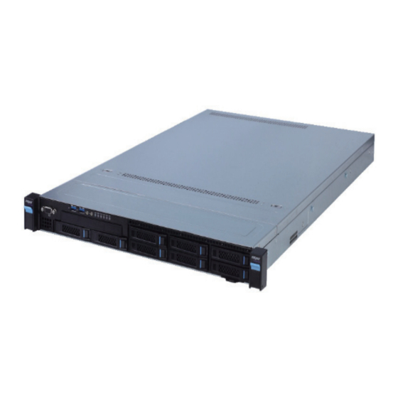
2. Product Specification Introduction 2.1 Introduction This type is a kind of server product developed independently. It adopts Intel Grantley- EP platform, and uses Wellsburg chip set. It supports two mainstream Intel Xeon E5-26** V3 series processors. It supports 24 DIMM DDR4 memory, up to 2133MHz. It supports ECC Registered and multiple senior memory redundancy functions. -
Page 12: Features And Specification
Product Specification Introduction 3.5”×4 configuration (i.e. full configuration) ● It supports 4 front set 3.5/2.5” SAS/SATA/SSD hard disks, and the related appearance is as shown in the following figure. Note: 3.5” hard disk bracket could hold 3.5”/2.5” hard disks. 2.2 Features and Specification Processor Intel dual-way Xeon E5-26XX V3 Series (supports up to two Processor Type... - Page 13 SAS Backplane SAS3.0 backplane It supports hog-plugging SAS/SATA/SSD hard disks. Network Card The mainboard integrates 1 Intel I350 dual Gigabit network card, Network Card ontroller providing two 1000M adaptive RJ45 network ports. It supports 1 network sub-card. Management Chip It integrates 1 independent 1000Mbps network interface, which is Management Chip used in IPMI remote management.
-
Page 14: Front Panel
Product Specification Introduction Host Size 430 width × 44 height × 730 depth (unit: mm) Gross weight: 26kg. (Gross weight includes: Host + Packing Box + Product Weight Rail + Parts Kit) Environment Parameters Working Environment 10 ℃ -35 ℃ Temperature Storage &... - Page 15 2.3.2 3.5×4 Disk Position Module Name Server is fixed with the cabinet CD Driver Front set VGA interface Front set USB 3.0 interface Server switch button ID light and button System fault indicator button Front set SSD hard disk slot Front set hard disk slot 3.5×8 disk position hard disk sequence diagram 2.3.3 Front Control Panel Buttons and Indicators...
-
Page 16: Rear Panel
Product Specification Introduction Module Name USB interface Server switch button ID light and button Network status indicator Memory fault indicator Power fault indicator System overheating indicator Fan fault indicator System fault indicator 2.3.4 Indicators on Hard Disk Bracket Number Module Name Description Constant green: Normal Hard disk activity status indicator... -
Page 17: Mainboard Layout
Module Name Power supply 0 Power supply 1 PCIE slot 0-1 VGA interface IPMI management interface USB 3.0 interface Gigabit network port ID light and button Network sub card slot 2.5 Mainboard Layout Module Name Memory slot (corresponding with CPU1) CPU1 12... - Page 18 Product Specification Introduction Module Name Memory slot (corresponding with CPU0) CPU0 System fan interfaces (8 interfaces in all) SATA interface CMOS clear jumper CPU0 supply interface Front set USB interface Built-in USB interface PCIE Riser card interface (corresponding with CPU0) Built in serial ports TPM interface IPMB interface...
-
Page 19: Mainboard Jumper Introduction
2.6 Mainboard Jumper Introduction 2.6.1 Clear CMOS Jumper Introduction See [2.5 Mainboard Layout] for jumper positions. Jumper No. Function Description Jumper Functions Short-circuit pin1-2, to restore normal status; short- CLR_CMOS CMOS clear jumper circuit pin2-3, to clear CMOS. Note:It is required to shut down the system, as well as disconnect power supply during CMOS cleaning, and hold for 5 seconds after short-circuiting Pin2-3;... -
Page 20: Bios Configuration
BIOS Configuration 3 BIOS Configuration This chapter introduces BIOS function setup and mainboard jumper of the server. All operations described in this section are only limited to operators or administrators with system maintenance qualification. BIOS is a basic input and output system. The system parameter and the hard drive parameter can be adjusted through special set program. -
Page 21: Bios Configuration
Control key instruction table Press Key Function <Esc> Exit or return from sub-menu to main menu. <←>or<→> Select a menu. <↑>or<↓> Move the cursor up or down. <Home>or<End> Move the cursor to top or bottom of the screen. Select the previous or next numerical value or setting of the <+>or<->... -
Page 22: Trusted Computing
BIOS Configuration 3.2.2 Advanced Menu Advanced Menu Interface Instruction Table Interface Parameters Function Description Trusted Computing Trustable computing configuration ACPI Settings Advanced configuration and power interface settings AST2400 Super IO Configuration AST2400 I/O chip parameter configuration Serial Port Console Redirection Serial port console redirection settings PCI Subsystem Settings PCI subsystem settings... - Page 23 Trusted Computing Menu Interface Instruction Table Interface Parameters Function Description Security Device Support BIOS’s security device support settings Current Status Information Status information of the current security device 3.2.2.2 ACPI Settings Advanced Menu Interface Instruction Table Interface Parameters Function Description Enable ACPI Auto Configuration To allow ACPI’s automatic configuration.
- Page 24 BIOS Configuration AST2400 Super IO Configuration Menu Interface Instruction Table Interface Parameters Function Description Super IO Chip The current I/0 chip Serial Port 1 Configuration Serial port 1 configuration 3.2.2.4 Serial Port Console Redirection Serial Port Console Redirection Menu Interface Instruction Table Interface Parameters Function Description Console Redirection...
- Page 25 Console Redirection Settings Menu Interface Introduction Interface Parameters Function Description Terminal Type Terminal type settings Bits per second Baud rate settings Data Bits Data bits settings Parity Parity check settings Stop Bits Stop bits settings Flow Control Flow control settings VT-UTF8 Combo Key Support VT-UTF8 Combo key support settings Recorder Mode...
- Page 26 BIOS Configuration 3.2.2.6 CSM Configuration CSM Configuration Menu Interface Instruction Table Interface Parameters Function Description CSM Support CSM support settings GateA20 Active A20 address line’s control mode settings Option Rom Message Option Rom display mode settings Boot option filter Boot option filter settings Option ROM execution Option Rom execution method Network...
- Page 27 USB Menu Interface Instruction Table Interface Parameters Function Description Legacy USB Support Legacy USB device settings Expansible host controller interface settings, orienting to XHCI Hand-off USB 3.0. Enhanced host controller interface settings, orienting to EHCI Hand-off USB2.0. USB Mass Storage Driver Support USB mass storage driver support settings Port 60/64 Emulation USB port 60/64h emulation settings...
-
Page 28: Chipset Menu
BIOS Configuration 3.2.3 Chipset Menu Chipset Menu Interface Instruction Table Interface Parameters Function Description Processor Configuration Processor configuration Advanced Power Management Advanced power management configuration Configuration QPI Configuration QPI configuration Memory Configuration Memory configuration IIO Configuration IIO configuration PCH Configuration PCH configuration Server ME Configuration Server ME configuration... - Page 29 Processor Configuration Menu Interface Instruction Table Interface Parameters Function Description Processor information sub-menu, and processor detailed Processor Information information. Hyper Threading Technology Hyper threading technology settings Core Enabled CPU core number settings Execute Disable Bit Virus protecting technology settings Intel TXT Support Intel trustable execution technology support settings Intel hardware-assisted virtualization technology settings Safe mode expansion settings...
- Page 30 BIOS Configuration Advanced Power Management Configuration Menu Interface Instruction Table Interface Parameters Function Description Power Technology To set power management Config TDP TDP settings CPU P State control sets sub-menu, and starts when Power CPU P State Control Technology is set to [Custom]. CPU C State control sets sub-menu, and starts when Power CPU C State Control Technology is set to [Custom].
- Page 31 CPU C State Control CPU C State Control Menu Interface Instruction Table Interface Parameters Function Description Package C State limit C state limit settings CPU C3 report C3 switching settings CPU C6 report C6 switching settings Enhanced Halt State (C1E) C1E switching settings Energy Performance Tuning 26...
- Page 32 BIOS Configuration Energy Performance Tunning Menu Interface Instruction Table Interface Parameters Function Description To select BIOS or OS to carry out energy performance Energy Performance Tunning tuning Energy Performance BIAS Energy performance management settings Workload Configuration Workload configuration 3.2.3.3 QPI Configuration QPI Configuration Menu Interface Instruction Table Interface Parameters Function Description...
- Page 33 3.2.3.4 Memory Configuration Memory Configuration Menu Interface Instruction Table Interface Parameters Function Description Enforce POR To execute POR settings Memory Frequency Memory frequency settings ECC Support ECC support settings Rank Multiplication Rank multiplication settings LRDIMM Module Delay LRDIMM module delay settings Data Scrambling Data scrambling settings Refresh Options...
- Page 34 BIOS Configuration Memory RAS Configuration Memory RAS Configuration Menu Interface Instruction Table Interface Parameters Function Description As for memory mode configuration, there’re 3 options of Memory Mode [Independent], [Mirroring] and [Lock Step]. Lockstep X4 DIMMs X4 DIMMs’ Lockstep switching settings Memory Rank Sparing Memory Rank hot sparing settings Correctable Error Threshold...
- Page 35 IIO Configuration Menu Interface Instruction Table Interface Parameters Function Description IIO0 configuration sub-menu, used to set link speed of IIO0 Configuration PCIE device of CPU0. IIO1 configuration sub-menu, used to set link speed of IIO1 Configuration PCIE device of CPU1. I/OAT Configuration Intel I/O acceleration technology configuration sub-menu.
- Page 36 BIOS Configuration PCH SATA Configuration Menu Interface Instruction Table Interface Parameters Function Description SATA Controller SATA controller switching settings As for SATA mode configuration, there’re two modes of Configure SATA as [AHCI] and [RAID] for setting. Information of hard disks connected to onboard SATA port SATA Port 0/1/2/3/4/5 0/1/2/3/4/5.
- Page 37 c 、 After entering SATA RAID configuration interface, menu list information, information of hard disk connecting to SATA controller (hard disk ID number, hard disk type, hard disk capacity as well as whether hard disk is a volume member etc.), existed RAID volume information (including volume ID number, name, RAID level, capacity, status, whether information bootable) will all display.
- Page 38 BIOS Configuration System displays the following menu options: Please enter a volume label name less than 16 characters without Name containing any special character. Please select RAID volume level, if no volume has been created at present, there’re four volume levels of RAID0(Stripe), RAID1(Mirror), RAID10(RAID0+1) and RAID5(Parity)for selection, please select volume level according to actual requirements.
- Page 39 Delete RAID Volume Menu After entering Delete RAID Volume menu, system prompts: “Deleting a volume will reset the disks to non-RAID. Warning:ALL DISKS DATA WILL BE DELETED.”. To delete an RAID volume, please press [DEL], system prompts: “ALL DATA IN THE VOLUME WILL BE LOST!”...
- Page 40 BIOS Configuration Exit Menu System prompts: “ Are you sure you want to exit?(Y/N): ” , enter “Y”, to exit SAS RAID configuration interface, enter “N”, to cancel exit operation. 3.2.3.7 Server ME Configuration Server ME Configuration Menu Interface Instruction Table Interface Parameters Function Description Operational Firmware Version...
- Page 41 3.2.3.8 Common Configuration Common Configuration Menu Interface Instruction Table Interface Parameters Function Description MMCFG Base MMCFG base address settings Isoc Mode Isoc mode settings MeSeg Mode MeSeg mode settings Numa Numa switching settings BIOS Guard BIOS guarding settings Integrated video card and external video card priority VGA Priority settings.
- Page 42 BIOS Configuration Server Mgmt Menu Interface Instruction Table Interface Parameters Function Description BMC Firmware Version BMC firmware version FRB-2 TImer FRB-2 clock settings FRB-2 Timer timeout FRB-2 clock expiration time settings FRB-2 Timer policy Policy settings after FRB-2 clock expiration OS Watchdog Timer System watchdog clock settings OS Wtd Timer timeout...
- Page 43 3.2.4.2 View FRU Information The View FRU Information menu lists BMC FRU information read by BIOS, and BIOS will interact with BMC at each system restart, keeping synchronous update of FRU information. 3.2.4.3 BMC network configuration BMC network configuration Menu Interface Instruction Table Interface Parameters Function Description Configuration BMC Network Status Parameter: It...
- Page 44 BIOS Configuration BMC network configuration on BIOS setup interface, is to configure BMC management network via BIOS. If no operation is carried out in BIOS, by default, it will read BMC, and configure its Dedicated management port and shareline management port, taking Dedicated management port as an example, the BIOS reading configuration is as shown in the following figure: BIOS could carry out Dynamic and Static network settings on BMC Dedicated management port and sharelink management port, taking Dedicated management port as an...
- Page 45 Enter to confirm, and an example is as shown in the following figure: When Static IP configuration is done, press F10 to save and restart, BIOS will carry out Static IP configuration for BMC. 3.2.4.4 BMC User Settings BMC User Settings Menu Interface Instruction Table Interface Parameters Function Description Add User...
- Page 46 BIOS Configuration Add User operation a 、 Select the User Name option, and press Enter to pop up the User Name box, enter the user name to set manually, after configuration is completed, press Enter to confirm. b 、 Select the User Password option, and press Enter to pop up the User Password box, enter the user password to set manually, after configuration is completed, press Enter to confirm.
- Page 47 Delete User operation Select the User Name option, and press Enter to pop up the User Name box, manually enter the user name to delete, after configuration is completed, press Enter to confirm. Select the User Password option, and press Enter to pop up the User Password box, manually enter the user password to delete, after that, press Enter to confirm, and the BMC USER SETTINGS INFO prompt will pop up, indicating user password deletion is done or not.
- Page 48 BIOS Configuration Select the User Name option, and press Enter to pop up the User Name box, manually enter the user name to modify, after configuration is completed, press Enter to confirm. Select the User Password option, and press Enter to pop up the User Password box, manually enter the user password, and press Enter to confirm.
- Page 49 System Temperature Information System Fan Speed System Voltage Information 44...
-
Page 50: Security Menu
BIOS Configuration 3.2.5 Security Menu Security Menu Interface Instruction Table Interface Parameters Function Description Administrator Password Create a password for administrator. User Password Create a password for normal user. 3.2.6 Boot Menu 45... - Page 51 Boot configuration Menu Interface Instruction Table Interface Parameters Function Description Bootup NumLock State Numlock keys status settings after bootup. Boot Options Retry The booting device polling settings To boot quietly, set this option to Enabled, and boot logo Quiet Boot displays as that set by manufacturer, disabled, boot logo displays as AMI’s default logo.
-
Page 52: Firmware Update
BIOS Configuration 3.2.7 Save & Exit Menu Save & Exit Menu Menu Interface Instruction Table Interface Parameters Function Description Save Changes and Exit To Save and exit Discard Changes and Exit To abandon changes and exit. Save Changes and Reset To save changes and reboot Discard Changes and Reset To abandon changes and reboot... - Page 53 When there’s no change in ME part, to update BIOS part, it is only required to execute command: afudos BIOS.bin /b /p /n /x. Parameter instructions: /b -- Program Boot Block /p -- Program Main BIOS /n -- Program NVRAM /x -- Don’t Check ROM ID /me -- Program ME Entire Firmware Block Use afudos tool to update BIOS in Linux OS...
- Page 54 BIOS Configuration put bin files of corresponding BIOS into this folder, and enter command: afuwinx64.exe BIOS.BIN /P /B /N /X /R, to update BIOS files. Meanwhile, GUI method is provided in Windows to refresh BIOS. Taking Windows 2008R2 OS as an example, use AFUWINGUI tool to update BIOS. Run AUWINGUI.EXE tool, as shown in the following figure: Click the Open button, after selecting the BIOS.bin file to update, system enters Setup interface automatically.
- Page 55 Select Program all Blocks and Do Not Check ROM ID options on Setup interface, click flash button, system enters Progress interface automatically, and executes BIOS update accordingly according to colors shown on the right, thus BIOS update is done as shown in the following figure: 50...
-
Page 56: Bmc Configuration
BMC Configuration 4 BMC Configuration 4.1 Introduction This chapter introduces specifications and main functions to be abided by management software. The distributor server management software is a control unit realizing server management, which is compatible with management standard of the server industry IPMI2.0 specification. -
Page 57: Functional Modules
Supports to store accounts in Active Directory server, and direct certification to server, so as to realize management system login with domain accounts. 4.2 Functional Modules This chapter introduces The distributor server management system module composition as well as functions of these modules. 4.2.1 Module Composition The distributor server management system is mainly composed of IPMI module, command line module, WEB module, KVMOver IP and virtual media etc. -
Page 58: Web Interface Introduction
BMC Configuration drive or CD/floppy disk iso file) in the form of virtual CD driver and floppy drive on server via internet. To use the remote control function, the Client needs to be equipped with browser of corresponding version and Java runtime environment, as shown in the following table. (The table is to be supplemented) Instructions: If Java runtime environment does not comply with requirements, user could login... - Page 59 2. Click “Login”, to enter the management interface. 4.3.2 Web Interface Introduction The Web interface helps users to accomplish server management via its visual and friendly interface, and the Web interface contains online help, so users could query instructions and operation guide on this interface via clicking button on any interface.
- Page 60 BMC Configuration event and log query, real-time monitoring, diagnosis and orientation, system maintenance, and system configuration etc. For detailed introduction on all functions, please refer to the following chapters. ● Specific operation interface is on the right of the interface. 4.3.3 Overall Situation Click System Abstract, to open the “System Abstract”...
- Page 61 56...
-
Page 62: Remote Control
BMC Configuration 4.4 Remote Control Select “Remote Control” on navigation tree, to open the remote control interface, which contains six interfaces of “Console Redirection (KVM)”, server switch-on/off control, server orientation, remote session configuration, virtual media configuration and mouse mode configuration, as shown in the following figure. ●... -
Page 63: Power Supply And Heat Radiation
4.5 Power Supply and Heat Radiation Select “Power Supply and Heat Radiation” on navigation tree, to open the power supply and heat radiation page, which contains three pages of power supply monitoring, power supply management, fan rotation rate control, as shown in the following figure. ●... -
Page 64: Bmc Configuration
BMC Configuration Low speed gear: About 20% duty ratio. ★ Medium speed gear: About 50% duty ratio. ★ High speed gear: About 80% duty ratio. ★ Full speed gear: 100% duty ratio. ★ 4.6 BMC Configuration Select “BMC Configuration” on navigation tree, to open the BMC configuration page, which contains 10 pages of “BMC Network”, “Service Configuration”, “NTP Configuration”, “SMTP Configuration”, “Alarming Management”, “Active Directory Configuration”, “LDAP/ E-Directory”, “User Configuration”, “IP Access Control”, “NCSI Network Card Selection”,... - Page 65 ● SMTP configuration: Sets SMTP server information related to alarming. ● Alarming management: Sets information about BMC management module alarming event filtering and alarming targets etc. ● Active directory configuration: Carries out related configuration on BMC active directory. ● LDAP/E-Directory: Carries out related configuration on BMC’s LDAP. ●...
- Page 66 BMC Configuration 61...
- Page 67 62...
-
Page 68: Logs
BMC Configuration 4.7 Logs Select “Logs” on navigation tree, to open related log page, which contains four pages of “System Event Logs”, “BMC System Design Logs”, “Black Box Logs”, “Event Logs Configuration”, “BMC System Audit Logs Configuration”, as shown in Figure 2-26, Figure 2-27, Figure 2-28 and Figure 2-29. -
Page 69: Fault Diagnosis
4.8 Fault Diagnosis Select “Fault Diagnosis” on navigation tree, to open fault diagnosis page, which contains three pages of “Task Restart”, “Last Crash Screen” and “System Power On Self test codes”. As shown in the following figure. ● Task restart: Contains restart two functions of restarting BMC and restarting KVM service;... -
Page 70: System Maintenance
BMC Configuration 4.9 System Maintenance Select “System Maintenance” on navigation tree, to open system maintenance page, which contains three pages of “BMC Firmware Update”, “BIOS Firmware Update” and “Restore Factory Configuration”. As shown in Figure 2-33, Figure 2-34 and Figure 2-35. ●... -
Page 71: Command Line Function Introduction
4.10 Command Line Function Introduction About this chapter It introduces Web interface of management system as well as operation steps to login Web interface. ● Login command line Introduces methods of login command line. ● Command line function introduction Introduces command line functions. 66... - Page 72 BMC Configuration 4.10.1 Command line login: Command line using ssh to login BMC, default user name: root, and default password: rootuser. After login, you could enter the command line interface: Enter help, you could view online help: 4.10.2 Command Line Function Introduction 4.10.2.1 Network Information Acquisition and Configuration: You could acquire and configure BMC’s network information via ipconfig instruction: 67...
- Page 73 4.10.2.2 Sensor Information Acquisition: Via sensor instruction, you could acquire all sensor information lists: 4.10.2.3 FRU Information Acquisition and Configuration: Via FRU instruction, you could acquire FRU configuration information: 4.10.2.4 Chassis Status Acquisition and Control: Via chassis instruction, you could acquire and control system power status. 68...
- Page 74 BMC Configuration Acquiring system power status: 4.10.2.5 User Acquisition, Adding and Deleting: Via user instruction, you could acquire the user list, to add or delete users. Acquiring user list: 4.10.2.6 BMC Version Acquisition and BMC Restart Via mc instruction, you could acquire BMC version information, and restart BMC. 69...
- Page 75 Acquiring BMC version information: 4.10.2.7 Fan Work Mode Configuration and Fan Rotation Rate Acquisition: Via fan instruction, you could either set fan work mode, or acquire fan rotation rate. Fan rotation rate acquisition: 4.10.2.8 Power Module Information Acquisition and Configuration: Via Psu instruction, you could either acquire power module information, or set power module as main output.
-
Page 76: Time Zone Table
BMC Configuration Power module information acquisition: 4.10.2.9 Change Root Password: Via password instruction, you could change root user’s password: 4.11 Time Zone Table Time Zone Countries and Regions GMT-12:00 West Date Line GMT-11:00 Appiah, Niue, Pago Pago, Midway GMT-10:00 Fakaofo, Rarotonga, the island of Tahiti, Johnston, Hawaii GMT-09:30 Marquesas GMT-09:00... - Page 77 Abidjan, Accra, Bamako, Banjul, Laayoune, Bissau, Dakar, Dublin, Freetown, Greenland, the Canary Islands, Casablanca, Conakry, Reykjavik, Lisbon, GMT+00:00 London, Monrovia, Nouakchott, Saint Lome, how beautiful, St. Helena, Ouagadougou Algiers, Amsterdam, Andorra, Oslo, Paris, Berlin, Bangui, Porto Novo, Budapest, Brazzaville, Brussels, Tirana, Douala, Ndjamena, Copenhagen, GMT+01:00 Warsaw, Kinshasa, Lagos, Liebe Weil, Luxemburg, Luanda, Rome, Madrid, Malta, Monaco, Niamey, Stockholm, Guinea, Zurich, Tunisia, Vaduz, Vienna,...
-
Page 78: Hardware Maintenance
Hardware Maintenance 5 Hardware Maintenance 5.1 Tool Preparation ● Tools to be prepared before construction, as shown in the following table. Tool List Illustration Name Description Phillips Used to fix bolts. Screwdriver Used to contact or Anti-static Wrist operate devices and Strap apparatuses, to prevent static electricity. - Page 79 Step 1: Open two pull rods on CPU slot, and open CPU fixing plate. Step 2: Install CPU into CPU slot, and then remove protective cover on CPU slot. Step 3: Clamp CPU with CPU fixing plate, and then fix two pull rods firmly. Step 4: Fix CPU heat radiator above CPU, and fasten bolts on heat radiator.
- Page 80 Hardware Maintenance ● It is required to coat thermal grease evenly onto contact position between CPU heat radiator and CPU. ● Fins of CPU heat radiator must be installed in the direction corresponding to system inlet/outlet. ● During fixing CPU heat radiator, it is required to fasten bolts according to diagonal sequence accordingly.
- Page 81 ● Memory installation principle: Only memory of the same type could be used in the same machine. Detailed memory installation and combination principles are as follows: The white slot shall take the priority, while CPU1 memory shall be symmetrically installed with CPU0. For single CPU, memory shall follow the screen printing sequence: CHA-0, CHB-0, CHC-0, CHD-0, CHA-1…...
- Page 82 Hardware Maintenance Step 2: Pop up buckles on hard disk bracket automatically, flatten and dismantle hard disk bracket. Step 3: Use four hard disk bolts to fix the hard disk onto the bracket. Step 4: Install the hard disk into the server, and fasten hard disk buckles firmly. 5.2.4 Power Replacement Step 1: Pull power catch in the direction of the arrow.
- Page 83 Step 2: Remove the power horizontally with even force. Step 3: Install power module. Push the new power module into the sliding channel, until a “click” sound is heard, power spring leaf is caught into the buckle automatically, and power module could not move any more.
- Page 84 Hardware Maintenance 5.2.6 Replace Riser Card and PCIE Expansion Card Step 1: Align two fingers to holes on Riser bracket, to take out the Riser card. Step 2: Pull out the expansion card in the arrow direction, and replace with a new expansion card.
- Page 85 5.2.7 Wind Scooper Replacement Step 1: Open upper cover of the chassis. Step 2: Use fingers to lift up both ends of the wind scooper, and remove the wind scooper vertically. 5.2.8 USB Flash Disk Replacement Step 1: Decide USB Flash disk position. Step 2: Remove the USB Flash disk along reversal direction of USB interface.
- Page 86 Hardware Maintenance 5.2.9 Mainboard Replacement Step 1: Dismantle all parts and cables connecting to mainboard. Step 2: Lift spring fixed legs on mainboard, then move the mainboard forward to remove the hardy hole, and vertically remove the mainboard upwards. 5.2.10 Replace Hard Disk Backplane Steps: Depart hard disk backplane from fixed legs of the chassis, vertically remove the chassis buckles upwards, and then remove the hard disk backplane outwards.
-
Page 87: Frequent Faults, Diagnosis And Troubleshooting
6. Frequent Faults, Diagnosis and Troubleshooting This chapter introduces Frequent server faults as well as corresponding diagnosis and troubleshooting suggestions. 6.1 Frequent Faults No power after startup After the machine is connected with power cable, no power is provided for the machine while pressing the On/Off button, and indicator does not light up after power on. -
Page 88: Diagnosis And Exclusion Instructions
Frequent Faults, Diagnosis and Troubleshooting 6.2 Diagnosis and Exclusion Instructions Diagnosis and exclusion on power-on failure at startup Description: After pressing the power button, server front control panel indicator (power-on status indicator, hard disk status indicator) is off, meanwhile, no KVM (display) output is displayed, and server chassis fan does not rotate. - Page 89 b 、 Test on another display d 、 If no solution could be achieved via the above operation, please contact the distributor customer service. Front panel status indicator alarms Description: The server is under normal operation, but system status indicator on front control panel flashes or the red indicator is on to alarm.
- Page 90 Frequent Faults, Diagnosis and Troubleshooting USB interface problem Description: Unable to use devices with a USB interface. Operation steps: a 、 Make sure operation system on server supports USB devices. b 、 Make sure system has been installed with correct USB device driver. c 、...
-
Page 91: Specifications
7 Specifications This chapter introduces various access authentications achieved by this product and standards it complies with. ● USA FCC statement. Introduces FCC standards abided by the product. ● CE statement of EU. Introduces CE standards abided by the product. ●... -
Page 92: China Environmental Symbols
Specifications This product is a class A product, in daily life, it may cause radio disturbance, in this case, it is required to adopt practicable precautions against its disturbance. 7.4 China Environmental Symbols The products comply with China environmental symbols criteria. Name of Hazardous Substances or Elements in the Product &...
Need help?
Do you have a question about the NF5180M4 and is the answer not in the manual?
Questions and answers