Table of Contents
Advertisement
Quick Links
Dear users of Inspur server:
Sincerely than you for selection of Inspur server!
This manual introduces the technical characteristics and the system
installation and setup of the server, and helps you to particularly understand
and expediently use this server.
Please deliver the package of our product to the waste recycling station
for recycling, in favor of pollution prevent and benefi t the humankind.
This manual is the property of the Inspur Group Co., Ltd.
This User Manual is not to be copied by any group or person in any
manner without the consent of Inspur Group Co., Ltd. The Inspur Group
Co., Ltd. reserves the right of revise this manual momentarily.
Any alteration about the content of this manual will be noticed.
Please contact Inspur Group Co., Ltd., if you have any questions or
advice about this manual.
"Inspur" is registered trademark of Inspur Group Co., Ltd.
Other trademarks belong to other corresponding registered companies.
Inspur Group Co., Ltd.
st
1
2013
Advertisement
Table of Contents

Related Manuals for Inspur NX8840


Summary of Contents for Inspur NX8840
- Page 1 This manual is the property of the Inspur Group Co., Ltd. This User Manual is not to be copied by any group or person in any manner without the consent of Inspur Group Co., Ltd. The Inspur Group Co., Ltd. reserves the right of revise this manual momentarily.
- Page 2 7. The copyrights of the markers and names of the software and hardware product referred in this manual are the property of corresponding companies. 8. In the above statement, “us” indicates the Inspur Group Co., Ltd. The Inspur Group Co., Ltd. holds the right of fi nal explanation about the above statement.
-
Page 3: Safety Information
— Close the cover of the host, re-connect the system to the power socket, and then start the equipment. — In case of operation failure or abnormal situation, please contact Inspur and get technical support. 3. Pay attention to the position of the system cables and power cables, wire them in places not to be stepped on or knocked down and ensure not to place other objectives on the cables. - Page 4 7. When dismounting the internal components with the approval of Inspur, please pay attention to the following matters: — Switch off the system power supply and disconnect the cables, including disconnecting any connection of the system.
- Page 5 Inspur; only maintenance technicians trained by Inspur have the right to disassemble the cover of the host, dismount and replace the internal components.
- Page 6 spike or plunge of the voltage, please use relevant voltage stabilizing equipment or uninterruptible power supply equipment. Warning 3: If extended cables are needed, please use the three-core cables matched with correct earthed plug, and check the ratings of the extended cables to make sure that the sum of rated current of all products inserted into the extended cables do not exceed 80% of the limits of the rated currents of the extended cables.
- Page 7 If what you bought is the chassis, besides carefully read the installation description attached with the cabinet products and get known about the special warning notices and installation process, you must abide by the following preventive measures to guarantee the cabinet to be stable and safe: Warning 10: Before installing equipment in the chassis, please install front and side supporting feet on the independent chassis;...
- Page 8 ● Common Problem and Trouble-shooting We suggest you read this manual seriously before you use this server for fear the unnecessary faults in your operation. Technical Service Tel.: 86-531-88546554 Address: NO.1036 Langchao Road, Jinan, China, Inspur Group Co., Ltd Post Code: 250101...
-
Page 9: Table Of Contents
Chapter One NX8840 Computer Blade Overview ..........1 1.1 NX8840 Computer Blade Technical Specifi cation ........1 1.2 NX8840 Computer Blade View ..............1 1.3 NX8840 Computer Blade Unit Interface and Indicator Introduction ...1 1.4 Usage of NX8840 Computer Blade ..............2 1.5 Jumper Setting ....................2 Chapter Two System BIOS ..................5... -
Page 11: Chapter One Nx8840 Computer Blade Overview
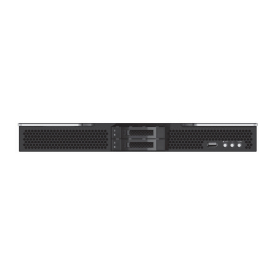
Supports 2 25-inch hot plug SATA, SSD and SAS hard disks. 1.2 NX8840 Computer Blade View Front view of NX8840 computer blade is as shown in the following Figure 1-1: Figure 1-1 NX8840 Front View 1.3 NX8840 Computer Blade Unit Interface and Indicator Introduction... -
Page 12: Usage Of Nx8840 Computer Blade
NX8840 computer blade shall use with Inspur I800 server, and computer blade could only be used when installed in I8000 server system, about how to install NX8840 blade onto an I8000 server, please refer to related parts in I8000 server use manual or illustration on chassis of I8000 blade server host, which is not repeated here. - Page 13 Open upper panel of the chassis To modify mainboard jumper, please open upper panel of the chassis, under authorization of Inspur Group Co., Ltd. Opening methods are as follows: 1. Shut down the system, pull out blade module, and press unlock spring;...
- Page 14 Chapter One NX8840 Computer Blade Overview Figure 1-5 Jumper Position Illustration Jumper No. Function Description Jumper Functions Short circuit of Pin1-2, normal status; CMOS clear jumper short circuit Pin2-3, clear CMOS. Note: It is required to maintain 5 seconds when short circuit Pin2-3 during clearing CMOS;...
-
Page 15: Chapter Two System Bios
Chapter Two System BIOS Chapter Two System BIOS 2.1 How to Enter the BIOS Setup Power on the server, system starts to boot, when the following content appears at the bottom of the screen: “Press <DEL> to SETUP or <TAB> to POST”, press [DEL] key, wait to enter system BIOS Setup. -
Page 16: Main Menu
Chapter Two System BIOS Operation key instructions: Press Key Description ↑ (Up Key) To select the previous menu or value. ↓(Down Key) To select the next menu or value. ← (Left Key) To select the left menu or value. → (Right Key) To select the right menu or value. - Page 17 Chapter Two System BIOS ● BIOS Information Displays system BIOS version, BIOS modifi cation time. ● Memory Information Displays system memory volume. ● System Date Sets system date, the format is [Week Day/Month/Year] ● System Time Sets system time, adopting 24-hour system, and the format is [Hour/Minute/ Second].
- Page 18 Chapter Two System BIOS Main and common options will be introduced in the following. ◇ Launch PXE OpROM There’re two options of [Disabled] and [Enabled], which are both open by default. ● WHEA Confi guration ◇ WHEA Support WHEA is a universal function of basic structure provided for handling hardware errors on Windows platform, and there’re two options of [Disabled] and [Enabled], which are both open by default.
- Page 19 Chapter Two System BIOS ◇ Serial-ATA Controller 0 This option only appears when SATA Mode option is set to [IDE Mode], which could be set to [Disabled], [Enhanced] and [Compatible]. ● SAS Confi guration After entering this option, situation of SATA equipment connected to all SATA interfaces will display.
- Page 20 Chapter Two System BIOS 2.2.3.1 North Bridge Figure 2-4 ● IOH Confi guration This menu is mainly used to set open and close of VT-d as well as speed of PCIE port. Figure 2-5 ◇ Intel(R) VT for Direct I/O Confi guration Whether Directed I/0 supports Intel virtualization technology.
- Page 21 Chapter Two System BIOS Equalization WA’s] synchronously. ● QPI Confi guration Sub-menu options of this menu could be used to set QPI speed mode and frequency etc. ● Memory Mode A s f o r m e m o r y m o d e c o n f i g u r a t i o n , t h e r e ’ r e f o u r o p t i o n s o f [Independent],[Mirroring], [Lock Step] and [Sparing], and the default is [Independent].
- Page 22 Chapter Two System BIOS no device tagging function, with correction capacity reduced. ● Data Scrambling When this function is enabled, it could avoid signal error caused by continuous ‘0’ or ‘1’ occurred in single bit. ● Thermal Throttling There’re three options [Disable][CLTT][OLTT]. Thermal Throttling is an over temperature protection function.
- Page 23 Chapter Two System BIOS ● Restore AC Power Loss Power status setting after system powered off.[Power 0ff] indicates a shutdown status, which needs to start up manually; [Last State] indicates a power-off status; [Power On] indicates an automatic startup status. ●...
- Page 24 Chapter Two System BIOS ● BMC Support There’re two options of [Enable] and [Disable], controlling interaction information between BIOS and BMC. ● BMC network confi guration This menu is used to display information configuration on BMC network interface. 2.2.5 Boot Menu Boot menu is mainly used to set priority of system guiding equipment.
- Page 25 Chapter Two System BIOS 2.2.6 Security Menu Figure 2-9 ● Administrator Password This option is used to set system administrator password. When administrator password is set, it is required to input password on user level or above when entering BIOS setup. ●...
- Page 26 Chapter Two System BIOS Figure 2-10 ● Save Changes and Exit Select this option, press [Enter], and select [Yes] in prompt popped up, all changes made in BIOS configuration will be saved, and system will exit BIOS confi guration. This menu function could be realized using shortcut key [F10]. ●...
- Page 27 Chapter Two System BIOS changes made in BIOS confi guration will be discarded, and system will not exit BIOS confi guration. ● Restore Defaults Select this option, press [Enter] and select [Yes] to confirm, default system optimal settings will be loaded, while system will not exit BIOS confi guration. This menu function could be realized using shortcut key [F9].
-
Page 28: Chapter Three Operation System Installation
During manual installation of operation system, some operation systems may need to use fl oppy drive or Inspur U drive disk to load driver of hard drive controller, as for methods to make floppy drive of driver, users could refer to readme.pdf fi... - Page 29 If an Inspur drive U disk or a normal U disk is used: ① Make hard disk controller driver program into [3.5 floppy disk (A:)] of an Inspur drive U disk or a normal U disk; ② When power on server to install operation system, connect an Inspur drive U...
- Page 30 ④ System pops up a window, indicating to insert an installation media containing driver program fi les, select [OK] directly when using an Inspur drive U disk, select path containing the drive when using a normal U disk, then select [OK];...
- Page 31 “Do not display this console during login” and then close the interface. 3. Install chip set patch ① Input Inspur drive CD into the drive, in automatic play interface popped up after running CD, click install or run blue dolphin icon under operation program option, enter navigation code on CD cover of driver in navigation code interface, click [Ok] to enter installation interface automatically;...
- Page 32 Chapter Three Operation System Installation Software] option; ⑥ Enter welcome to use interface, click [Next] to continue; ⑦ Enter “License Agreement” interface, select “I accept terms in this license agreement”, and then click [Next] to continue; ⑧ Enter “Installation Options” interface, click [Next] to continue; ⑨...
-
Page 33: Manual Installation Of Red Hat Enterprise Linux 6.2
Chapter Three Operation System Installation ① Insert an Inspur drive CD into CD driver, in autoplay interface popped up after running, click install or run blue dolphin icon under program option, input navigation code on drive CD cover in Please enter navigation code interface, click [OK] to enter installation interface automatically;... - Page 34 Chapter Three Operation System Installation Choose Skip to skip the media test and start the installation. 4. Enter RED HAT ENTERPRISE LINUX 6 interface, select [Next] to continue installation. 5. System enters “What language would you like to use during the installation process?”...
- Page 35 Chapter Three Operation System Installation installation method selection interface, there are the following installation options: Use All Space Replace Existing Linux System(s) Shrink Current System Use Free Space Create Custom Layout This installation takes custom manual partition as an example, select “Create Custom layout”, and click [Next] to continue.
- Page 36 [Finish] to fi nish installation. 26. Input Username and Password to login the system. 3.2.3 Load HCA Card Drive 1. Insert Inspur drive CD into the driver, left click [Applications]→[Accessories/ System Tools]→[Terminal] on desktop Input mount -o ro,loop MLNX_OFED_LINUX-<ver>-<OS label>.iso /mnt in...
- Page 37 Chapter Three Operation System Installation terminal window occurred: 2. Enter /mnt directory to run installation script, to complete drive installation automatically /mnt/mlnxofedinstall (1) Input “mst start” in terminal window after drive installation Starting MST (Mellanox Software Tools) driver set Loading MST PCI module - Success Loading MST PCI confi...
-
Page 38: Chapter Four Integrated Raid System
Chapter Four Integrated RAID System Chapter Four Integrated RAID System This chapter mainly introduces configuration of mainboard integrated SATA controller RAID and its usage. To use a mainboard integrated SATA RAID, it is required to enter BIOS, set Chipset→PCH→SCU devices option to [Enabled], and then set Onboard SATA Oprom option to [Enabled]. - Page 39 Chapter Four Integrated RAID System 4 executable menus in this SATA RAID confi guration interface are listed in the following: ● Create RAID Volume To create an RAID volume. ● Delete RAID Volume To delete an existed RAID volume. ● Reset Disks to Non-RAID To reset hard disks in RAID volume, and to restore them to non-RAID status.
- Page 40 Chapter Four Integrated RAID System only available when hard disk quantity is 4 or above. RAID5 ( Parity ): This RAID volume is allowed to be made on 3 or above hard disks. Disks : Select hard disks to make RAID volume, press enter after this option is selected, system will enter hard disk selection interface, please select hard disks to make RAID volume using space key in succession, and then press enter to return to volume create menu.
- Page 41 Chapter Four Integrated RAID System hard disks, system prompts whether to reset hard disks, key in “Y” or “N” according to prompt. Note: While resetting hard disk, data on this disk will all be lost, meanwhile, this disk will not belong to RAID volume any more. IV ....
-
Page 42: Chapter Five Common Problems And Troubleshooting
Chapter Five Common Problems and Troubleshooting Chapter Five Common Problems and Troubleshooting This chapter introduces the information concerning common problems and trouble removal. If you are not sure the failure cause and removal method, please contact our customer service center for solution. Note: When replacing or installing the hardware device for the server, please disconnect the power cable from the server completely. - Page 43 ● Because the navigation serial number is different when storage confi guration has been changed, so you should obtain the new navigation serial number from Inspur technical support before you change your storage confi guration.
- Page 44 3. Clean the rolling wheel and drive shaft of the mouse. 4. It is suggested that you use the keyboard and mouse tested for compatibility by Inspur group or replace with other keyboard and mouse for testing. 5.2.5 System blue screen, halt or restart...
-
Page 45: Other Notices
3. After understanding the basic information, please feedback the detail alarm information to Inspur technical support personnel as soon as possible. We will make further analysis and judgment and help you to solve the problem as soon as possible. -
Page 46: Technical Support Information
5. For notices of more products, please refer to the FAQ for server in official website of Inspur: http://www.inspur.com/support/Channel_Home/support_sv.asp 5.4 Technical support information If you have any doubt or unsolved problems in using Inspur server, please take the following measures: 1. If you have doubt in product configuration and detail specification, please contact your supplier.
Need help?
Do you have a question about the NX8840 and is the answer not in the manual?
Questions and answers