Table of Contents
Advertisement
Quick Links
Dear User of Inspur Tiansuo Server:
Heartfelt thanks to you for your use of Inspur Tiansuo Server.
This manual introduces the technical attribute and the system set up and
installation, which facilitate you to fully understand and expediently use this server.
Please deliver the package of our product to the waste recycling station, in favor
of pollution prevention and humankind benefit.
This manual is the property of the Inspur Group Co., Ltd.
This User Manual is not to be copied by any group or person in any manner
without the consent of Inspur Group Co., Ltd. The Inspur Group Co., Ltd. reserves the
right of revising this manual at any time.
Any alteration about the content of this manual will not be informed.
Please contact Inspur Group Co., Ltd. if you have any questions or advice about
this manual.
"Inspur" is the registered trademark of Inspur Group Co., Ltd.
Other trademarks respectively belong to their corresponding registered corporations.
Inspur Group Co., Ltd.
August, 2014
Advertisement
Table of Contents

Related Manuals for Inspur TS860


Summary of Contents for Inspur TS860
- Page 1 This manual is the property of the Inspur Group Co., Ltd. This User Manual is not to be copied by any group or person in any manner without the consent of Inspur Group Co., Ltd. The Inspur Group Co., Ltd. reserves the right of revising this manual at any time.
- Page 2 8. The copyrights of the markers and names of the software and hardware product referred in this manual are the property of corresponding companies. 9. In the above statement, “us” indicates the Inspur Group Co., Ltd.; Inspur Group Co., Ltd. reserves the right of final explanation about the above statement.
- Page 3 Regarding the Manual ● Brief Introduction This chapter introduces module assembly, technical features, appearance and I/O interface specification, etc, of the whole server. ● System setup This chapter introduces the settings of BIOS. ● Install OS This chapter introduces how to install the mainstream OS on this server. ●...
-
Page 4: Chapter One Brief Introduction
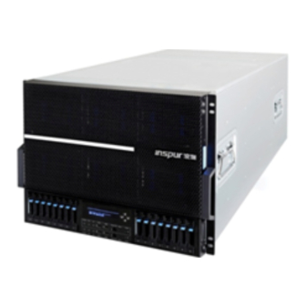
Chapter one Brief Introduction Inspur TS860 is an 8U large-scale Rack server, which can support 8*Intel Xeon E7-88XX V2 processors, compatible with E7-48XX V2 processors(only single 4way and dual partition configuration support); It supports 192*DDR3 RDIMMS in maximum and 6TB system memory. - Page 5 Note: If you plan to install the server in the cabinet, please refer to the attached “Quick Guide” for installation instruction after carrying out the host. Unpack computing modules TS860 server system concludes two computing modules which are separately packaged in one box upon receipt. Then 2 processing modules are packaged by carton as whole.
-
Page 6: Technical Specifications
1. Split the rubber seal on the box with paper cutter and take out the pad on the 2 separately-packaged computing modules.。 2. Take out the computing module from the box and then take out the anti-static bags, and the serial number of each computing module can be identified by the label on the left side of modules. - Page 7 GPU can only be installed in the PCIE x16 slot of the basic IO module. Hard disk Hard disk type 2.5 inch SAS/SATA/SSD HDD Support max.16*2.5 inch HDD Quantity Each IO Riser card can support 2*M-SATA External memory driver CD-ROM USB CD-ROM (optional) Inspur driving U Inspur driving U disk (optional) disk...
-
Page 8: Front View
Power supply Support 8*800W redundant power supply module, support N+N/N+M Specification redundancy(N Min.3) Power input Please refer to our host nameplate label in the specification Physical specification External Host machine: 1168mm × 722mm × 587mm (depth x width x height) dimension of Module:1168mm ×... - Page 9 Name Description Chassis panel Installed in front of the computing module for dustproof. to indicate the start process through the change of light length change when starting the system; Indicator light to indicate the system pressure through the change of the light color in the process of system operation.
- Page 10 minutes, then the indicator light skips starting process and directly to the power dissipation display stage. 2. Once the BMC starts, it will send the OS starting process to the indicator light: a. if the operating system has been started, the indicator light will quickly finish the starting process bar to jump to power dissipation display stage b.
- Page 11 Name Description Green indicator is on: normal running of the system after startup Status indicator Indicator is off: the system is not powered up normally Information indicator Red indicator is on: system failure The indicator is on when confirming the system ID ID indicator The function needs the management software to realize this function...
- Page 12 going on in the hard disk The red indicator is on: hard disk failure Rebuild: The red indicator twinkles: the hard disk is being rebuilt Rear view Basic IO Expasion IO Module2 module2 IO Riser (optional) Basic IO Expansion Module1 IO module1 IO Riser Trigger...
- Page 13 PSU 0~3 power distribution board; PDU0 Each power input interface support 2 PSU PSU 4~7 power distribution board; PDU1 Each power input interface support 2 PSU PSU0-3 PSU 0~3 PSU4-7 PSU 4~7 IO Riser port Network port0 Network port1 Network port2 Network port3 USB port Management...
-
Page 14: Chapter Two: System Setup
1. First correctly connect the monitor, keyboard and mouse. Then connect all power modules with the effective power strip or outlet by using the attached power cable. 2. Press the switch button on the front panel of the server, the fan will run and system start to power up and self-test. -
Page 15: How To Enter The Bios Setup
How to Enter the BIOS Setup Power on and start the server, when displaying the Inspur logo, “Press Esc for Boot menu” shows at the bottom of the screen, then press【ESC】 button, and system enters into BIOS setup screen. - Page 16 Option Description system guide management manual, free to choose to start from Boot Manager which device Setup Utility enter BIOS settings interface 1.Continue Select this option and press [enter] button, you will overleap BIOS setup, continue the system-guiding operation. 2. Boot Manager Select this option and press [enter] button, the following system bootable option list will display.
-
Page 17: Bios System Menu Introduction
BIOS system menu introduction BIOS setup programs of this product mainly consist of the following function menu: Name Function Set up basic system time, system date, display BIOS Main version, CPU type, system memory capacity, etc. Advanced Set up CPU, advanced features as integrated SATA controller Security Set up administrator password... - Page 18 Main menu Enter BIOS setup procedure, firstly shows the Main menu, from which you can 首 see BIOS version, CPU type, system memory capacity, etc. You can also set up BIOS interface language, system time, system date. When setting system time and date, select the options with arrow key, then press 【Enter】,subfield is selected, afterwards, set the field value with +/- key.
-
Page 19: Advanced Menu
Advanced menu This menu is mainly for the setting of advanced menu, if malfunctioned, system may work abnormally,factory settings is recommended. The following is the introduction of the main submenu. ● Advanced Processor * CPU Package Detected Display CPU quantity * Socket 0/1/2/3/4/5/6/7 CPU Information Display the current CPU details, including CPU type, basic frequency, CPU cores, thermal design power, etc. - Page 20 Policy Performance/Balanced pops up selection window by pressing the [enter] key. Energy/Energy Efficient When disabling EIST Support, this option is not visible. Default is Balanced Performance. Whether enable dynamic transformation Dynamic Enabled/Disabled characteristics of power consumption performance Switching adjustment, Default is Enabled. Enable or disable processor turbo mode.
- Page 21 storage device, please set this option to [IDE] Use integrated SATA controller, if no RAID, and connect to 1-2 SATA, please set this option to[AHCI] Use integrated SATA controller, if to make SATA Host RAID, please set this option to[RAID] * Serial ATA Port 0/1 Display SATA status connected to SATA ports ●...
- Page 22 completely, you can flip through Pagedown or Page up to view it. ● Memory RAS Configuration To set memory RAS features BIOS Setting Options Description Whether to enable memory Rank Sparing function. This function is backup a Rank, if there occurs a Rank with many ECC errors on Memory Rank Sparing Disable/Enable a memory board, then the system will enable...
- Page 23 [Last State]:Status before power off ● H2O IPMI Configuration To check BMC state, Firmware version, BMC MAC address, IP and other information and configure BMC. * IPMI Support To enable and disable support for IPMI.
-
Page 24: Security Menu
Security menu ● Supervisor Password Display whether system administrator password has been set, unable to be set. ● Set Supervisor Password To set administrator password. After setting, enters BIOS Setup procedure, you must enter the administrator password, or some administrator privileges will be limited... -
Page 25: Boot Menu
Boot menu The menu is mainly for the setting of priority between system startup process and the system boot device. ● Network Stack Open or close support for network protocol stack,[Enabled]setting can support PXE. ● PXE Boot Capability To select the setting booted by integrated network card, available only after enabling Network Stack. - Page 26 Exit menu Options in this menu can save or give up BIOS modified settings and exit setup procedure. ● Exit Saving Changes Select this option and press [enter] key, in the pop-up prompt, select [Yes], it will save modifications made in BIOS setup and exit the BIOS setup. The menu function can use [F10] to achieve.
-
Page 27: Clear Cmos
2.2 Clear CMOS Clear basic IO module If the following operations are needed, please get the authorization of Inspur Group Co., Ltd. Clear basic IO module according to the following methods: 1. Power off the system (turn off the AC power);... -
Page 28: Chapter Three: Operating System Installation
During manual setup of the operating system, some operating system may need the floppy drive or Inspur driver U disk to load the driving program of hard disc controller. Refer to the readme.pdf file under the root directory in Inspur system driving program CD for the making method of the driving program floppy disk. -
Page 29: Preparation Before Installation
Inspur driver U disk, operating as follows: Using Inspur driver U disk to load driver: ①Please make the disk controller driver in the Inspur driver U disk [3.5 floppy disk (A :)] partition. ② Please connect Inspur driver U disk to the USB interface of the server;... -
Page 30: Install Driver
3.1.3 Install Driver 1. Install Chipset driver ① Insert Inspur driver CD, click the blue dolphin icon under the installation or operation procedure item in the automatically playing interface popped out after the disk’s running, input the navigation code on the driver CD case in the navigation code verification... - Page 31 ⑨ Complete the installation, click <Finish> according to the prompts 2.Install Network card driver After the installation of the chipset patch, do not take out the Inspur driver CD, but continue the installation of network card driver ① In the “Select OS” column, select Windows 2012;...
- Page 32 Take out Inspur driver CD, and reboot system. Complete the installation of Windows Server 2012. 3.2 Manually Installation of Red Hat Enterprise Linux 6.4 3.2.1 Preparation before installation ● Red Hat Enterprise Linux 6.4 installation CD (DVD)(X86_64bit version) ●Inspur driver CD ●...
- Page 33 5. Enter RED HAT ENTERPRISE LINUX 6 interface, select [Next] to continue. 6. Enter “What language would you like to use during the installation process?” interface, select the language you need during the installation, here we select “English(English)”, and then select [Next] to continue.
- Page 34 actual needs to. ①create root partition(/) and boot partition: select root partition in Mount point:/, select the hard disk need installing system in Allowable Drives windows, input the size of the partitions in Size(MB), click [OK] to complete the creation of root partition. Creating the boot partitionin the same way: /boot.
-
Page 35: Chapter Four: Common Problems And Troubleshooting
3.2.3 Install VGA card driver After the installation of OS, You can manually load VGA card driver using the attached driver CD 1. insert Inspur driver CD into optical disc driver, click Terminal menu in Applications→System Tools, and input in the window: #mount /dev/cdrom... -
Page 36: Restarting The Server
3. Disconnect the power cable from the system and open the chassis to check. 4. Check the fastness of the cable connection and accessory plugging in the chassis. 5. Remove other external components other than Inspur’s. 6. Pack the chassis, connect the power cable correctly and start the machine. - Page 37 6. If the machine is installed with components other than Inspur ones, please remove them first. 7. With the permission of Inspur technical support personnel, you may pull and plug RAM and clear CMOS for test. 4.2.3 Installation system can’t find hard disk 1.
-
Page 38: Machine Alarm
For blue screen, restart or halt of the machine in the utilization of the windows system, you may resort to the following measures: 1. If other external non-Inspur components or some application program software are installed before the fault, it is suggested removing it and going on to test your server. -
Page 39: Additional Notes
4. For more notices of our products, please refer to the FAQ for server in the official website of Inspur: http://www.inspur.com/support/Channel_Home/support_sv.asp 4.4 If you have questions or encounter insoluble problem in the process of using Inspur server, please take the following measures: 1. -
Page 40: Chapter Five: Integrated Management Function Introduction
400-8600011 Emil: sv_str_pcs@inspur.com Inspur server driver and product material download link: http://www.inspur.com/support/Channel_Home/support_sv.asp Chapter Five: Integrated management function introduction This product integrates remote management card, you can remote login the server through remote management card. Following gives an introduction of integrated remote management card. -
Page 41: Function Menu Introduction
interface as follows: Please input default administrator Username and Password: Username:admin Password:admin Note: The default user name and password that has all the permissions to set and configure all the modules, to ensure system security, it is recommended timely change password after you log 5.2 function menu introduction After logging in, shows the following default interface: On the left top of the interface, you can see the menu including the following functions:... - Page 42 Recording, Maintenance and Firmware Update. On the right top of the interface, there are user name and login user's user groups, you can also use Refresh (refresh the page), Print (print pages), Logout (cancellation) and other shortcut menu. Dashboard menu In this interface, you can see the Firmware version of management chip, modification time, MAC address and other information.
- Page 43 ① Sensor Readings menu: Display all the sensor value, mainly including temperature, voltage, fan speed, hard drive and power status. You can refresh and display sub-categories. ② Event Log menu: Display sensor events, BIOS event, systems management software event, OEM events, remote console software event log. It can be classified can also be unified and you can check the log anytime, the log can also be cleared.
- Page 44 modify IP address or select DHCP according to actual need. 3, NTP menu: To set the date and time synchronized with a time server, you can also set the time on your own. If you need to select time synchronization server for remote management, please enter the address of the time synchronization server.
- Page 45 ●in tool→<Internet>→<higher>option, do not mark the "Do not save encrypted pages to disk" option and save it, showing as follows:...
- Page 46 A. Remote desktop: Video menu Menu Function Pause Redirection Pause Remote Desktop Display Resume Redirection Restore Remote Desktop Display Refresh Video Refresh Remote Desktop Display Capture Screen Achieve Remote desktop screenshots Compression Mode Compression mode settings Dct Quantization Table Remote desktop display quality settings Host Video Output Open or close host machine output video display Full Screen...
- Page 47 B. remote desktop: Keyboard menu Menu Function Hold Right Ctrl Key Select this option, the operation is equivalent to pressing the right side of the "Ctrl" key Hold Right Alt Key Select this option, the operation is equivalent to pressing the right side of the "Alt"...
- Page 48 Menu Function Show Cursor Select this option, in the remote desktop display the local mouse and redirected screen mouse at the same time. Mouse Mode Select this option to set mouse mode. D. remote desktop: Options menu Menu Function Bandwidth Select this option, you can set the display bandwidth Keyboard/Mouse Encryption Keyboard and mouse encryption setting...
- Page 49 USB Image]; then click [Browse], Select the path/ location where the mirroring is, and then click the appropriate [Connect] button to complete the mirroring loading. If the CD in the synchronized client optical disc driver is a bootable CD or a system installation disk, please set the client CD as the first boot sequence in the server BIOS setup.
- Page 50 Server Power Control menu: Display the current power status, providing server restart, immediately shut down, orderly close-down, boot, system power off and power on again, totally five options. Select the options you need to perform, click [Perform Action] to execute. 3, Auto Video Recording menu The function menu can set Video Recording functions, and download the file to view the automatically recorded Video.
- Page 51 The function menu can achieve remote BMC Firmware upgrades and IPMI Remote Management Card restart. 1, Preserve Configuration This menu can select the configuration options in the list of items not to be modified before loading factory defaults or upgrading Firmware. The selected option will not change because of loading factory defaults or Firmware upgrading.
- Page 52 Inspur. ① In Firmware Update menu interface, click [Enter Update Mode]. In the confirmation pop-up window, click [OK], wait to enter the following interface. ② click "Browse" after input box and select the ROM mirroring (* .ima file) you want to update from the client's disk, as shown below: ③...
- Page 53 If you choose TFTP protocol, you also the need to set server address, mirroring path (including mirroring file name). After changing the settings, you need to click [Save] to save. If you do not want to save the setting parameters, click [Reset].
Need help?
Do you have a question about the TS860 and is the answer not in the manual?
Questions and answers