Table of Contents

Subscribe to Our Youtube Channel
Related Manuals for Kontron CP6003-RA/RC


Summary of Contents for Kontron CP6003-RA/RC
- Page 1 » User Guide « CP6003-RA/RC Rugged 6U CompactPCI Processor Board based on the 2 Generation Intel® Core™ i7 Processor with the Intel® QM67 Express Chipset Doc. ID: 1046-3890, Rev. 1.0 December 16, 2011 If it’s embedded, it’s Kontron.
-
Page 2: Imprint
Disclaimer Copyright © 2011 Kontron AG. All rights reserved. All data is for information purposes only and not guaranteed for legal purposes. Information has been carefully checked and is believed to be accurate; however, no responsibility is assumed for inaccuracies. Kontron and the Kontron logo and all other trademarks or registered trademarks are the property of their respective own- ers and are recognized. -
Page 3: Table Of Contents
CP6003-RA/RC Preface Table of Contents Revision History ......................ii Imprint ........................ii Disclaimer ........................ii Table of Contents ...................... iii List of Tables ......................ix List of Figures ......................xiii Proprietary Note .......................xv Trademarks ......................xv Environmental Protection Statement ................xv Explanation of Symbols ..................xvi For Your Safety ...................... - Page 4 Preface CP6003-RA/RC Functional Description ............2 - 3 2.1 Processor ....................2 - 3 2.2 Memory ....................2 - 4 2.3 Intel® QM67 Express Chipset ..............2 - 4 2.4 Timer ......................2 - 5 2.5 Watchdog Timer ..................2 - 5 2.6 Battery .....................2 - 5 2.7 Reset .......................2 - 5...
- Page 5 CP6003-RA/RC Preface 2.10.13.2 Board Functionality when Installed in Peripheral Slot ..2 - 23 2.10.13.3 Packet Switching Backplane (PICMG 2.16) ......2 - 23 2.10.13.4 Hot Swap Support ..............2 - 23 2.10.13.5 Power Ramping ..............2 - 23 2.10.13.6 Precharge ................2 - 23 2.10.13.7 Handle Switch (CP6003-RA) ..........
- Page 6 4.3 Jumper Description ..................4 - 6 4.3.1 COMB Termination Jumper Settings ..........4 - 6 4.4 I/O Address Map ..................4 - 7 4.5 CP6003-RA/RC-Specific Registers ............4 - 8 4.5.1 Status Register 0 (STAT0) ...............4 - 8 4.5.2 Status Register 1 (STAT1) ...............4 - 9 4.5.3...
- Page 7 Regulation ................5 - 5 5.2 Power Consumption of CP6003-RA/RC ..........5 - 5 5.2.1 Power Consumption of the CP6003-RA/RC Accessories ....5 - 8 5.2.2 Power Consumption per Gigabit Ethernet Port ....... 5 - 8 5.3 Maximum Power Consumption of PMC Modules ........5 - 8 5.4 Maximum Power Consumption of XMC Modules ........
- Page 8 Preface CP6003-RA/RC This page has been intentionally left blank. Page viii ID 1046-3890, Rev. 1.0...
-
Page 9: List Of Tables
Standards for the CP6003-RC ..............1 - 21 Related Publications ................1 - 22 Features of the Processors Supported on the CP6003-RA/RC ....2 - 4 IPMI LEDs and Hot Swap LED Function ........... 2 - 7 Watchdog LED and Temperature Status LED Function ......2 - 8 Debug LEDs Function ................ - Page 10 Preface CP6003-RA/RC 2-28 CompactPCI Rear I/O Connector J5 Pinout ..........2 - 32 2-29 CompactPCI Rear I/O Connector J5 Signals ........... 2 - 33 DIP Switch SW1 for CompactPCI Interface Configuration ......4 - 3 DIP Switch SW2 for PMC Interface Configuration ........4 - 3 DIP Switch SW3 for Boot Configuration .............
- Page 11 CP6003-RA/RC Preface Power Consumption of CP6003-RA/RC Accessories ....... 5 - 8 5-10 Power Consumption per Gigabit Ethernet Port ........5 - 8 5-11 PMC/CCPMC Module Current ..............5 - 8 5-12 XMC/Conduction-Cooled XMC Module Current ........5 - 9 Maximum Reference Point Temperature with Core™ i7-2715QE ..... 6 - 9 Maximum Reference Point Temperature with Core™...
- Page 12 Preface CP6003-RA/RC This page has been intentionally left blank. Page xii ID 1046-3890, Rev. 1.0...
-
Page 13: List Of Figures
CP6003-RA/RC Preface List of Figures CP6003-RA/RC Functional Block Diagram ..........1 - 7 CP6003-RA Front Panel ................1 - 8 CP6003-RA Board Layout – Top View ............ 1 - 9 CP6003-RC Board Layout – Top View ..........1 - 10 CP6003-RA Board Layout –... - Page 14 Preface CP6003-RA/RC This page has been intentionally left blank. Page xiv ID 1046-3890, Rev. 1.0...
-
Page 15: Proprietary Note
Kontron without further notice. Trademarks Kontron, the PEP logo and, if occurring in this manual, “CXM” are trademarks owned by Kontron, Kaufbeuren (Germany). In addition, this document may include names, company logos and trademarks, which are registered trademarks and, therefore, proprietary to their respective owners. -
Page 16: Explanation Of Symbols
Preface CP6003-RA/RC Explanation of Symbols Caution, Electric Shock! This symbol and title warn of hazards due to electrical shocks (> 60V) when touching products or parts of them. Failure to observe the pre- cautions indicated and/or prescribed by the law may endanger your life/health and/or result in damage to your material. -
Page 17: For Your Safety
However, the life expectancy of your product can be drastically reduced by improper treatment during unpacking and installation. Therefore, in the interest of your own safety and of the correct operation of your new Kontron product, you are requested to conform with the following guidelines. -
Page 18: General Instructions On Usage
CP6003-RA/RC General Instructions on Usage In order to maintain Kontron’s product warranty, this product must not be altered or modified in any way. Changes or modifications to the device, which are not explicitly approved by Kontron and described in this manual or received from Kontron’s Technical Support as a special handling instruction, will void your warranty. -
Page 19: Two Year Warranty
As a result, the products are sold “as is,” and the responsibility to ensure their suitability for any given task remains that of the purchaser. In no event will Kontron be liable for direct, indirect or consequential damages resulting from the use of our hardware or software products, or documentation, even if Kontron were advised of the possibility of such claims prior to the purchase of the product or during any period since the date of its purchase. - Page 20 Preface CP6003-RA/RC This page has been intentionally left blank. Page xx ID 1046-3890, Rev. 1.0...
-
Page 21: Introduction
CP6003-RA/RC Introduction Chapter Introduction ID 1046-3890, Rev. 1.0 Page 1 - 1... - Page 22 Introduction CP6003-RA/RC This page has been intentionally left blank. Page 1 - 2 ID 1046-3890, Rev. 1.0...
-
Page 23: Board Overview
PCI interface. When installed in the system slot, the interface is enabled, and when installed in a peripheral slot, the CP6003-RA/RC is isolated from the CompactPCI bus. Safety and security features via a Trusted Platform Module (TPM) 1.2 are provided on request. Intelligent Platform Management Interface (IPMI) is supported as well. -
Page 24: Cp6003-Ra Board-Specific Information
Introduction CP6003-RA/RC CP6003-RA Board-Specific Information The CP6003-RA is a rugged air-cooled CompactPCI single-board computer with front I/O. It is based on the 2 generation Intel® Core™ i7 processor and specifically designed for use in highly integrated platforms with solid mechanical interfacing for a wide range of industrial environment applications. -
Page 25: Cp6003-Rc Board-Specific Information
CP6003-RA/RC Introduction CP6003-RC Board-Specific Information The CP6003-RC is a rugged conductive-cooled CompactPCI single-board computer without front I/O. It is based on the 2 generation Intel® Core™ i7 processor and specifically designed for use in highly integrated platforms with solid mechanical interfacing for a wide range of industrial environment applications. -
Page 26: System Expansion Capabilities
1.4.3 SATA Flash Module The CP6003-RA/RC provides support for up to 32 GB NAND flash memory in combination with an optional SATA Flash module, which is connected to the CP6003-RA/RC via an onboard SATA extension connector. For further information concerning the SATA Flash module, please refer to Appendix A. -
Page 27: Board Diagrams
CP6003-RA/RC Introduction Board Diagrams The following diagrams provide additional information concerning board functionality and component layout. 1.6.1 Functional Block Diagram Figure 1-1: CP6003-RA/RC Functional Block Diagram ID 1046-3890, Rev. 1.0 Page 1 - 7... -
Page 28: Front Panel
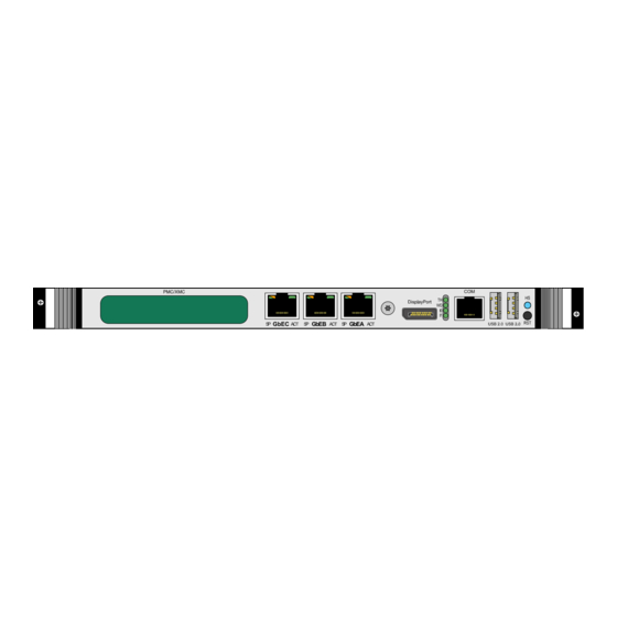
Introduction CP6003-RA/RC 1.6.2 Front Panel Figure 1-2: CP6003-RA Front Panel Legend: IPMI LEDs I0/I1 (red/green): Indicate the software status of the IPMI controller Status LEDs WD (green): Watchdog Status TH (red/green): Temperature Status HS (blue): Hot Swap Control Integral Ethernet LEDs... -
Page 29: Board Layout
CP6003-RA/RC Introduction 1.6.3 Board Layout Figure 1-3: CP6003-RA Board Layout – Top View Battery 1 2 3 4 Intel® QM67 PMC/XMC Magnetics GbE C 33 34 DDR3 Memory GbE B SATA Flash Module GbE A Magnetics gen. Intel® Core™ i7... -
Page 30: Cp6003-Rc Board Layout - Top View
Introduction CP6003-RA/RC Figure 1-4: CP6003-RC Board Layout – Top View Intel® QM67 PMC/XMC Magnetics 33 34 DDR3 Memory SATA Flash Module Magnetics gen. Intel® Core™ i7 Page 1 - 10 ID 1046-3890, Rev. 1.0... -
Page 31: Cp6003-Ra Board Layout - Bottom View
CP6003-RA/RC Introduction Figure 1-5: CP6003-RA Board Layout – Bottom View Temperature Sensor DLED 0 DLED 1 DLED 2 DLED 3 ID 1046-3890, Rev. 1.0 Page 1 - 11... -
Page 32: Cp6003-Rc Board Layout - Bottom View
Introduction CP6003-RA/RC Figure 1-6: CP6003-RC Board Layout – Bottom View R771 R759 R778 R756 IPMI LED I0 Temperature Sensor IPMI LED I1 DLED 0 DLED 1 DLED 2 DLED 3 Page 1 - 12 ID 1046-3890, Rev. 1.0... -
Page 33: Technical Specification
DMI 2.0 with 5 GT/s and FDI interfaces to the Intel® QM67 chipset • One x8 and two x4 PCI Express 2.0 ports operating at 5 GT/s • Please contact Kontron for further information concerning the suitability of other Intel processors for use with the CP6003-RA/RC. Memory Main Memory: Up to 16 GB, dual-channel, soldered DDR3 SDRAM memory with ECC •... - Page 34 ENUM signal handling is in compliance with the PICMG 2.1 Hot Swap Specification. When installed in a peripheral slot, the CP6003-RA/RC is isolated from the CompactPCI bus. It receives power from the backplane and supports rear I/O and, if the system supports it, packet switching (in this case up to two channels of Gigabit Ethernet).
- Page 35 CP6003-RA/RC Introduction Table 1-2: CP6003-RA/RC Main Specifications (Continued) FEATURES SPECIFICATIONS Rear I/O The following interfaces are routed to the rear I/O connectors J3 and J5. COMA (RS-232 signaling) and COMB (RS-422/RS-232 signaling); no • buffer on the rear I/O module is necessary 4 x USB 2.0...
- Page 36 Introduction CP6003-RA/RC Table 1-2: CP6003-RA/RC Main Specifications (Continued) FEATURES SPECIFICATIONS Serial ATA One Serial ATA 6 Gb/s interfaces for: One onboard SATA 6 Gb/s interface for the Serial ATA Flash module (up • to 32 GB flash memory) Four SATA 3 Gb/s ports accessible via rear I/O...
- Page 37 CP6003-RA/RC Introduction Table 1-2: CP6003-RA/RC Main Specifications (Continued) FEATURES SPECIFICATIONS Watchdog Timer Software-configurable, two-stage Watchdog with programmable timeout • ranging from 125 ms to 4096 s in 16 steps Serves for generating IRQ or hardware reset • System Timer The Intel® QM67 chipset contains three 8254-style counters which have •...
- Page 38 Operating Systems The board is offered with various Board Support Packages including Windows, VxWorks and Linux operating systems. For further information concerning the operating systems available for the CP6003-RA/RC, please contact Kontron. Page 1 - 18 ID 1046-3890, Rev. 1.0...
- Page 39 Note ... When additional components are installed, refer to their opera- tional specifications as this will influence the operational and stor- age temperature of the CP6003-RA/RC. Battery (CP6003-RA) 3.0V lithium battery for RTC with battery socket. Battery type: UL-approved CR2025 Temperature ranges: Operational: -20°C to +70°C...
-
Page 40: Standards
Customers desiring to perform further environmental testing of Kontron prod- ucts must contact Kontron for assistance prior to performing any such testing. This is necessary, as it is possible that environmental testing can be destructive when not performed in accordance with the applicable specifications. -
Page 41: Standards For The Cp6003-Rc
CP6003-RA/RC Introduction Table 1-4: Standards for the CP6003-RC TYPE ASPECT STANDARD REMARKS Emission EN55022 EN61000-6-3 Immission EN55024 EN61000-6-2 Electrical Safety EN60950-1 Mechanical Mechanical Dimensions ANSI / VITA 30.1 95% RH at +30°C to +60°C, condensing Environmental Climatic Humidity ANSI / VITA 47... -
Page 42: Related Publications
CompactPCI System Management Specification PICMG 2.9 Rev. 1.0 CompactPCI Hot Swap Specification PICMG 2.1 Rev. 2.0 IPMI - Intelligent Platform Management Interface Specification v2.0 Kontron CompactPCI Backplane Manual, ID 24229 PMC Module IEEE 1386-2001, IEEE Standard for a Common Mezzanine Card (CMC) Family IEEE 1386.1-2001, IEEE Standard Physical and Environmental Layers for PCI... -
Page 43: Functional Description
CP6003-RA/RC Functional Description Chapter Functional Description ID 1046-3890, Rev. 1.0 Page 2 - 1... - Page 44 Functional Description CP6003-RA/RC This page has been intentionally left blank. Page 2 - 2 ID 1046-3890, Rev. 1.0...
-
Page 45: Processor
2.2 GHz. The 2 generation Intel® Core™ i7 processors used on the CP6003-RA/RC include an inte- grated high-performance graphics controller and a DDR3 dual-channel memory controller with ECC support as well as one x8 and two x4 PCI Express 2.0 ports operating at 5 GT/s. They support various technologies, such as: •... -
Page 46: Memory
Intel® QM67 Express Chipset The CP6003-RA/RC is equipped with the mobile Intel® QM67 Express Chipset, a highly integrat- ed platform controller hub (PCH) with the following features: • Two x4 or eight x1 PCI Express 2.0 ports operating at 5 GT/s (only one x4 PCI Express port is used on the CP6003-RA/RC) •... -
Page 47: Timer
Functional Description • Intel® High Definition Audio (HDA) interface • Analog display port • Three digital display ports (only up to three ports are used on the CP6003-RA/RC) • Integrated RTC Timer The CP6003-RA/RC is equipped with the following timers: •... -
Page 48: Flash Memory
2.8.1 SPI Boot Flash for uEFI BIOS The CP6003-RA/RC provides two 8 MB SPI boot flashes for two separate uEFI BIOS images, a standard SPI boot flash and a recovery SPI boot flash. The fail-over mechanism for the uEFI BIOS recovery can be controlled via the IPMI controller or the DIP switch SW3 on the CP6003- RA and a configuration resistor on the CP6003-RC. -
Page 49: Board Interfaces
CP6003-RA/RC Functional Description 2.10 Board Interfaces 2.10.1 Onboard and Front Panel LEDs The CP6003-RA is equipped with two IPMI LEDs (I0 and I1), one Watchdog Status LED (WD LED), one Temperature Status LED (TH LED), and one Hot Swap LED (HS LED) on the front panel and four onboard Debug LEDs (DLED 0..3) located on the rear side of the board. -
Page 50: Watchdog Led And Temperature Status Led
Functional Description CP6003-RA/RC 2.10.1.2 Watchdog LED and Temperature Status LED The CP6003-RA provides one Watchdog Status LED (WD LED) and one Temperature Status LED (TH LED). Note ... If the TH LED flashes red at regular intervals, it indicates that the processor junction temperature has reached a level beyond which permanent silicon dam- age may occur. -
Page 51: Debug Leds
Functional Description 2.10.1.3 Debug LEDs The CP6003-RA/RC provides four onboard Debug LEDs (DLED0..3) located on the rear side of the board. They indicate the boot-up POST code after which they are available to the appli- cation. If the DLED0..3 are lit red during boot-up, a failure is indicated before the uEFI BIOS has start- ed. -
Page 52: Post Code Sequence
Under normal operating conditions, the Debug LEDs should not remain lit red during boot-up. They are intended to be used for debugging purposes. In the event that a Debug LED lights up red during boot-up or the CP6003-RA/RC does not boot, please contact Kontron for further assistance. -
Page 53: Dip Switches Sw1, Sw2 And Sw3 (Cp6003-Ra)
CP6003-RA/RC Functional Description 2.10.2 DIP Switches SW1, SW2 and SW3 (CP6003-RA) The CP6003-RA is equipped with two 2-bit DIP switches, SW1 and SW2, and one 4-bit DIP switch, SW3, which enable the board to be configured according to the application require- ments. -
Page 54: Usb Interfaces
One USB peripheral may be connected to each port. For connecting more USB devices to the CP6003-RA/RC than there are available ports, an external USB hub is required. Note ... The USB host interfaces can be used with maximum 500 mA continuous load current as specified in the Universal Serial Bus Specification, Revision 2.0. -
Page 55: Graphics Memory Usage
CP6003-RA/RC Functional Description 2.10.5.1 Graphics Memory Usage The 2 gen. Intel® Core™ i7 processor supports Dynamic Video Memory Technology (Intel® DVMT) with up to 512 MB memory. This technology ensures the most efficient use of all available memory for maximum 3D graphics performance. DVMT dynamically responds to application requirements allocating display and texturing memory resources as required. -
Page 56: Com Ports
I/O. It is not possible to use COMA on the front panel and the rear I/O simultaneously. Note ... The CP6003-RA/RC provides two jumpers, JP2 and JP3, used to activate the bus termination for the RS-422/RS-232 (COMB) port. For further information on the JP2 and JP3 jumpers, refer to Chapter 4.3, Jumper Description. -
Page 57: Gigabit Ethernet
Gigabit Ethernet interfaces on the rear I/O, PICMG 2.16 LPa, PICMG 2.16 LPb, LPc and LPd. The Boot from LAN feature is supported on the CP6003-RA/RC. The following table indicates the Gigabit Ethernet port mapping of the CP6003-RA/RC Table 2-14: Gigabit Ethernet Port Mapping... -
Page 58: Serial Ata Interface
2.10.8 Serial ATA Interface The CP6003-RA/RC provides five Serial ATA (SATA) interfaces with RAID support, one inter- face is implemented as onboard SATA connector and four SATA interfaces are available only on the rear I/O. The onboard SATA connector, J19, is used for mounting the SATA Flash mod- ule. -
Page 59: Pmc Interface
2.10.10 PMC Interface The CP6003-RA/RC provides a PMC interface with a dedicated PCI Express-to-PCI-X bridge from Pericom (PI7C9X130). This interface is configurable for either 64-bit/66 MHz PCI or 64- bit/133 MHz PCI-X operation and is compliant with the IEEE 1386.1-2001 specification, which defines a PCI electrical interface for the CMC (Common Mezzanine Card) form factor. -
Page 60: Pmc Connectors J15, J16, J17 And J18
Functional Description CP6003-RA/RC Figure 2-5: PMC Connectors J15, J16, J17 and J18 (Jn1) (Jn2) (Jn3) (Jn4) Page 2 - 18 ID 1046-3890, Rev. 1.0... -
Page 61: 2.10.10.1 Pmc Connectors J15, J16, J17 And J18 Pinout
CP6003-RA/RC Functional Description 2.10.10.1 PMC Connectors J15, J16, J17 and J18 Pinout Table 2-17: PMC Connectors J16 and J18 Pinout J16 (Jn1) J18 (Jn2) SIGNAL SIGNAL SIGNAL SIGNAL TCK (pull-up) -12V +12V TRST# (pull-down) Ground INTA# TMS (pull-up) TDO (NC) -
Page 62: Pmc Connectors J15 And J17 Pinout
Functional Description CP6003-RA/RC Table 2-18: PMC Connectors J15 and J17 Pinout J15 (Jn3) J17 (Jn4) SIGNAL SIGNAL SIGNAL SIGNAL PCI-RSV (NC) Ground Rear I/O Rear I/O Ground C/BE[7] Rear I/O Rear I/O C/BE[6] C/BE[5] Rear I/O Rear I/O C/BE[4] Ground... -
Page 63: Xmc Interface
2.10.11 XMC Interface The CP6003-RA/RC provides a x8 PCI Express 2.0 XMC interface operating at 5.0 GT/s and compliant with the ANSI/VITA 42.0 and ANSI/VITA 42.3 specifications. An XMC module (CP6003-RA) or a conductive-cooled XMC module (CP6003-RC) can be con- nected to the CP6003-RA/RC via the J14 connector. -
Page 64: Debug Interface
In a system slot, the CompactPCI interface can be either a 64-bit/66 MHz PCI or PCI-X inter- face via a dedicated PCI Express-to-PCI-X bridge from Pericom (PI7C9X130). The CP6003-RA/RC supports up to seven peripheral slots with 33 MHz and up to 4 peripheral slots with 66 MHz through a backplane. -
Page 65: Board Functionality When Installed In Peripheral Slot
2.10.13.5 Power Ramping On the CP6003-RA/RC a special hot swap controller is used to ramp up the onboard supply voltage. This is done to avoid transients on the +3.3V, +5V, +12V and -12V power supplies from the hot swap system. When the power supply is stable, the hot swap controller generates an onboard reset to put the board into a definite state. -
Page 66: Compactpci Bus Connector
• J3, J4 and J5 have rear I/O interface functionality • only J4 has rear I/O functionality from the PMC/ XMC module The CP6003-RA/RC is designed for a CompactPCI bus architecture. The CompactPCI standard is electrically identical to the PCI local bus. However, these systems are enhanced to operate in rugged industrial environ- ments and to support multiple slots. -
Page 67: 2.10.14.2 Compactpci Connectors J1 And J2 Pinout
CP6003-RA/RC Functional Description 2.10.14.2 CompactPCI Connectors J1 and J2 Pinout The CP6003-RA/RC is provided with two 2 mm x 2 mm pitch female CompactPCI bus connectors, J1 and J2. Table 2-21: CompactPCI Bus Connector J1 System Slot Pinout REQ64# ENUM# 3.3V... -
Page 68: Compactpci Bus Connector J1 Peripheral Slot Pinout
A * indicates that the signal normally present at this pin is disconnected from the CompactPCI bus when the CP6003-RA/RC is inserted in a peripheral slot. ** When the CP6003-RA/RC is inserted in a peripheral slot, the function of the RST# signal can be enabled or disabled. - Page 69 CP6003-RA/RC Functional Description Table 2-23: 64-bit CompactPCI Bus Connector J2 System Slot Pinout CLK6 CLK5 IPMB2_SDA IPMB2_SCL IPMB2_Alert PRST# REQ6# GNT6# DEG# FAL# REQ5# GNT5# AD[35] AD[34] AD[33] AD[32] AD[38] V(I/O) AD[37] AD[36] AD[42] AD[41] AD[40] AD[39] AD[45] V(I/O) AD[44]...
- Page 70 V(I/O) V(I/O) V(I/O) SYSEN# Note ... A * indicates that the signal normally present at this pin is disconnected from the CompactPCI bus when the CP6003-RA/RC is inserted in a peripheral slot. Page 2 - 28 ID 1046-3890, Rev. 1.0...
-
Page 71: 2.10.14.3 Compactpci Rear I/O Connectors J3-J5 And Pinout
I/O is compatible with all standard 6U CompactPCI passive backplanes with rear I/O sup- port. The CP6003-RA/RC conducts all I/O signals through the rear I/O connectors J3, J4 and J5. Table 2-25: CompactPCI Rear I/O Connector J3 Pinout RIO_5V RIO_5V RIO_3.3V... -
Page 72: Compactpci Rear I/O Connector J3 Signals
Functional Description CP6003-RA/RC The following table describes the signals of the J3 connector. Table 2-26: CompactPCI Rear I/O Connector J3 Signals SIGNAL DESCRIPTION COMA signaling (RS-232) COMB signaling (RS-422/RS-232) Graphic signaling USB0 to USB3 USB Port signaling SPEAKER Standard PC speaker... -
Page 73: Compactpci Rear I/O Connector J4 Pinout
CP6003-RA/RC Functional Description Table 2-27: CompactPCI Rear I/O Connector J4 Pinout PIM:1 PIM:3 PIM:2 PIM:4 PIM:5 PIM:7 PIM:6 PIM:8 RIO_5V RIO_3.3V PIM:9 PIM:11 PIM:10 PIM:12 PIM:13 PIM:15 PIM:14 PIM:16 PIM:17 PIM:19 PIM:18 PIM:20 PIM:21 PIM:23 PIM:22 PIM:24 PIM:25 PIM:27 PIM:26... -
Page 74: Compactpci Rear I/O Connector J5 Pinout
Functional Description CP6003-RA/RC Table 2-28: CompactPCI Rear I/O Connector J5 Pinout GPI3 PWM1:OUT PWM2:OUT BATT (3.0V) HDA:SYNC HDA:RST# HDA:SDOUT SYS_WP# GPO0 HDA:SDIN1 GPO1 HDA:SDIN2 HDA:SDIN0 HDA:BITCLK HDMI2:D0+ HDMI2:D0- HDMI2:D2+ HDMI2:D2- HDMI2:D1+ HDMI2:D1- HDMI2:HPDET GPO2 GPO3 HDMI2:CLK+ HDMI2:CLK- HDMI2:SDA HDMI2:SDC HDMI1:D0+... -
Page 75: Compactpci Rear I/O Connector J5 Signals
CP6003-RA/RC Functional Description The following table describes the signals of the J5 connector. Table 2-29: CompactPCI Rear I/O Connector J5 Signals SIGNAL DESCRIPTION SATA0..3 SATA Port 0..3 Signaling HDMI1 HDMI signaling HDMI2 HDMI signaling High-definition audio signaling Pulse width modulation output for fan GPIO General purpose digital input/output;... - Page 76 Functional Description CP6003-RA/RC This page has been intentionally left blank. Page 2 - 34 ID 1046-3890, Rev. 1.0...
-
Page 77: Installation
CP6003-RA/RC Installation Chapter Installation ID 1046-3890, Rev. 1.0 Page 3 - 1... - Page 78 Installation CP6003-RA/RC This page has been intentionally left blank. Page 3 - 2 ID 1046-3890, Rev. 1.0...
-
Page 79: Safety Requirements
Safety Requirements The following safety precautions must be observed when installing or operating the CP6003- RA/RC. Kontron assumes no responsibility for any damage resulting from failure to comply with these requirements. Warning! Due care should be exercised when handling the board due to the fact that the heat sink can get very hot. -
Page 80: Cp6003-Ra Installation
I/O devices refer to the appropriate sections in Chapter 3. Warning! Care must be taken when applying the procedures below to ensure that neither the CP6003-RA/RC nor other system boards are physically dam- aged by the application of these procedures. 3. To install the CP6003-RA perform the following: 1. -
Page 81: Standard Removal Procedures
(con- necting or disconnecting). Kontron disclaims all liability for damages or injuries resulting from failure to comply with the above. 3. Disconnect any interfacing cables that may be connected to the board. -
Page 82: Hot Swap Procedures
Installation CP6003-RA/RC 3.2.3 Hot Swap Procedures The CP6003-RA is designed for hot swap operation. When installed in the system slot, it is ca- pable of supporting peripheral board hot swapping. When installed in a peripheral slot, its hot swap capabilities depend on the type of backplane in use and the system controller’s capabil- ities. - Page 83 (con- necting or disconnecting). Kontron disclaims all liability for damages or injuries resulting from failure to comply with the above. 5. Unscrew the front panel retaining screws.
-
Page 84: Installation Of Cp6003-Ra Peripheral Devices
J19, i.e. the pins are aligned correctly and not bent. Note ... Only qualified SATA Flash modules from Kontron are authorized for use with the CP6003-RA. Failure to comply with the above will void the warranty and may result in damage to the board or the system. -
Page 85: Pmc/Xmc Module Installation
CP6003-RA/RC Installation 3.2.5 PMC/XMC Module Installation The CP6003-RA supports the installation of a PMC module via the connectors J15 to J18 or an XMC module via the connector J14. For the initial installation and standard removal of all PMC/XMC modules, refer to the documentation provided with the module. -
Page 86: Cp6003-Rc Installation
Installation CP6003-RA/RC CP6003-RC Installation 3.3.1 Initial Installation Procedures The following procedures are applicable only for the initial installation of the CP6003-RC in a system. Procedures for standard removal and hot swap operations of the CP6003-RC are found in their respective chapters. -
Page 87: Standard Removal Procedures
CP6003-RA/RC Installation 5. Using both hands, steadily apply enough force on the top and bottom of the front sur- face of the board to engage it with the backplane. Note ... The chassis of rugged systems do not necessarily provide an objective means of determining when the board is properly seated in the back- plane. -
Page 88: Hot Swap Procedures
Installation CP6003-RA/RC To relax the wedge lock, turn the wedge lock’s screw counter-clockwise using a 2.5 mm hex key until the screw is against the stop. Warning! Due care should be exercised when handling the board due to the fact that the heat sink can get very hot - danger of burns. - Page 89 CP6003-RA/RC Installation also be aware that the surrounding rugged system components and chassis can get very hot! Warning! Care must be taken when applying the procedures below to ensure that neither the CP6003-RC nor other system boards are physically damaged by the application of these procedures.
- Page 90 Installation CP6003-RA/RC 12. Carefully insert the “new” board into the “old” board’s slot until it makes contact with the backplane connectors. Note ... In rugged systems, the slot tolerances are very narrow. In the event that the board jams during insertion, remove it and ensure that both wedge locks are fully relaxed before proceeding with insertion.
-
Page 91: Installation Of Cp6003-Rc Peripheral Devices
CP6003-RA/RC Installation 3.3.4 Installation of CP6003-RC Peripheral Devices The CP6003-RC is designed to accommodate various peripheral devices, such as USB devic- es, CCPMC/conduction-cooled XMC modules, rear I/O devices, a SATA Flash module, etc.The following figure shows the placement of the SATA Flash module on the CP6003-RC. -
Page 92: Ccpmc/Conduction-Cooled Xmc Module Installation
Installation CP6003-RA/RC 3.3.5 CCPMC/Conduction-Cooled XMC Module Installation The CP6003-RA supports the installation of a CCPMC module via the connectors J15 to J18 or a conduction-cooled XMC module via the connector J14. For the initial installation and standard removal of all CCPMC/conduction-cooled XMC modules, refer to the documentation provided with the module. -
Page 93: Configuration
CP6003-RA/RC Configuration Chapter Configuration ID 1046-3890, Rev. 1.0 Page 4 - 1... - Page 94 Configuration CP6003-RA/RC This page has been intentionally left blank. Page 4 - 2 ID 1046-3890, Rev. 1.0...
-
Page 95: Dip Switches Sw1, Sw2 And Sw3 Configuration (Cp6003-Ra)
PCI 33 MHz / 66 MHz auto detection via the CompactPCI backplane PCI frequency configured to 33 MHz PCI / PCI-X mode auto detection via the CompactPCI backplane CP6003-RA/RC configured to PCI mode Table 4-2: DIP Switch SW2 for PMC Interface Configuration... -
Page 96: Dip Switch Sw3 For Boot Configuration
Configuration CP6003-RA/RC Table 4-3: DIP Switch SW3 for Boot Configuration SWITCH SETTING DESCRIPTION Boot-up with POST Code indication on the Debug LEDs Boot-up with no POST Code indication on the Debug LEDs Boot from the standard SPI boot flash Boot from the recovery SPI boot flash... -
Page 97: Configuration Resistors (Cp6003-Rc)
CP6003-RA/RC Configuration Configuration Resistors (CP6003-RC) The CP6003-RC is equipped with four configuration resistors, R756, R759, R771, and R778, used for uEFI BIOS boot configuration. Figure 4-2: Configuration Resistors (CP6003-RC) R759 R759 R771 R771 R778 R778 R756 R756 Table 4-4: Configuration Resistors’ Settings... -
Page 98: Jumper Description
CP6003-RA/RC Jumper Description The CP6003-RA/RC has three jumpers JP1, JP2, and JP3. JP1 is reserved for further use. JP2 and JP3 are used to activate the bus termination for COMB. For the location of the jumpers, refer to Figures 1-5 and 1-6. -
Page 99: I/O Address Map
CP6003-RA/RC Configuration I/O Address Map The following table indicates the CP6003-RA/RC-specific registers. Table 4-7: I/O Address Map ADDRESS DEVICE 0x080 uEFI BIOS POST Code Low Byte Register (POSTL) 0x081 uEFI BIOS POST Code High Byte Register (POSTH) 0x082 - 0x083... -
Page 100: Cp6003-Ra/Rc-Specific Registers
CP6003-RA/RC CP6003-RA/RC-Specific Registers The following registers are special registers which the CP6003-RA/RC uses to watch the onboard hardware special features and the CompactPCI control signals. Normally, only the system uEFI BIOS uses these registers, but they are documented here for application use as required. -
Page 101: Status Register 1 (Stat1)
CP6003-RA/RC Configuration 4.5.2 Status Register 1 (STAT1) The Status Register 1 holds board-specific status information. Table 4-9: Status Register 1 (STAT1) REGISTER NAME STATUS REGISTER 1 (STAT1) ADDRESS 0x281 RESET NAME DESCRIPTION ACCESS VALUE C66EN CPCI PCI speed (M66EN signal):... -
Page 102: Control Register 0 (Ctrl0)
Configuration CP6003-RA/RC 4.5.3 Control Register 0 (CTRL0) The Control Register 0 holds general/common control information. Table 4-10: Control Register 0 (CTRL0) REGISTER NAME CONTROL REGISTER 0 (CTRL0) ADDRESS 0x282 RESET NAME DESCRIPTION ACCESS VALUE 7 - 6 VGAM VGA CRT mode configuration:... -
Page 103: Control Register 1 (Ctrl1)
CP6003-RA/RC Configuration 4.5.4 Control Register 1 (CTRL1) The Control Register 1 holds board-specific control information. Table 4-11: Control Register 1 (CTRL1) REGISTER NAME CONTROL REGISTER 1 (CTRL1) ADDRESS 0x283 RESET NAME DESCRIPTION ACCESS VALUE SRST SATA Flash module reset: 0 = Reset of SATA Flash module... -
Page 104: Device Protection Register (Dprot)
Configuration CP6003-RA/RC 4.5.5 Device Protection Register (DPROT) The Device Protection Register holds the write protect signals for flash devices. Table 4-12: Device Protection Register (DPROT) REGISTER NAME DEVICE PROTECTION REGISTER (DPROT) ADDRESS 0x284 RESET NAME DESCRIPTION ACCESS VALUE System write protection:... -
Page 105: Reset Status Register (Rstat)
CP6003-RA/RC Configuration 4.5.6 Reset Status Register (RSTAT) The Reset Status Register is used to determine the host’s reset source. Table 4-13: Reset Status Register (RSTAT) REGISTER NAME RESET STATUS REGISTER (RSTAT) ADDRESS 0x285 RESET NAME DESCRIPTION ACCESS VALUE PORS Power-on reset status:... -
Page 106: Board Interrupt Configuration Register (Bicfg)
Configuration CP6003-RA/RC 4.5.7 Board Interrupt Configuration Register (BICFG) The Board Interrupt Configuration Register holds a series of bits defining the interrupt routing for the Watchdog. If the Watchdog timer fails, it can generate an IRQ5 interrupt. The enumeration signal is generated by a hot swap compatible board after insertion and prior to removal. -
Page 107: Status Register 2 (Stat2)
4.5.9 Board ID High Byte Register (BIDH) Each Kontron board is provided with a unique 16-bit board-type identifier in the form of a hexadecimal number. The Board ID High Byte Register is located in the address 0x288. The Board ID Low Byte Register is located in the address 0x28D. -
Page 108: Board And Pld Revision Register (Brev)
4.5.11 Geographic Addressing Register (GEOAD) This register holds the CompactPCI geographic address (site number) used to assign the In- telligent Platform Management Bus (IPMB) address to the CP6003-RA/RC. Table 4-18: Geographic Addressing Register (GEOAD) REGISTER NAME GEOGRAPHIC ADDRESSING REGISTER (GEOAD) -
Page 109: Watchdog Timer Control Register (Wtim)
4.5.12 Watchdog Timer Control Register (WTIM) The CP6003-RA/RC has one Watchdog timer provided with a programmable timeout ranging from 125 msec to 4096 sec. Failure to strobe the Watchdog timer within a set time period results in a system reset or an interrupt. The interrupt mode can be configured via the Board Interrupt Configuration Register (0x286). -
Page 110: Watchdog Timer Control Register (Wtim)
Configuration CP6003-RA/RC Table 4-19: Watchdog Timer Control Register (WTIM) REGISTER NAME WATCHDOG TIMER CONTROL REGISTER (WTIM) ADDRESS 0x28C RESET NAME DESCRIPTION ACCESS VALUE Watchdog timer expired status bit 0 = Watchdog timer has not expired 1 = Watchdog timer has expired. -
Page 111: Board Id Low Byte Register (Bidl)
4.5.13 Board ID Low Byte Register (BIDL) Each Kontron board is provided with a unique 16-bit board-type identifier in the form of a hexadecimal number. The Board ID Low Byte Register is located in the address 0x28D. The Board ID High Byte Register is located in the address 0x288. -
Page 112: Led Configuration Register (Lcfg)
Configuration CP6003-RA/RC 4.5.14 LED Configuration Register (LCFG) The LED Configuration Register holds a series of bits defining the onboard configuration of the Debug LEDs (DLED 0..3). For the location of the Debug LEDs, refer to Figures 1-5 and 1-6. Table 4-21: LED Configuration Register (LCFG) -
Page 113: Led Control Register (Lctrl)
CP6003-RA/RC Configuration 4.5.15 LED Control Register (LCTRL) This register is used to switch on and off the Debug LEDs (DLED 0..3). Table 4-22: LED Control Register (LCTRL) REGISTER NAME LED CONTROL REGISTER (LCTRL) ADDRESS 0x291 RESET NAME DESCRIPTION ACCESS VALUE... -
Page 114: General Purpose Output Register (Gpout)
Configuration CP6003-RA/RC 4.5.16 General Purpose Output Register (GPOUT) This register is used to control the general purpose output signals on the rear I/O CPCI connectors. Table 4-23: General Purpose Output Register (GPOUT) REGISTER NAME GENERAL PURPOSE OUTPUT REGISTER (GPOUT) ADDRESS... -
Page 115: Power Considerations
CP6003-RA/RC Power Considerations Chapter Power Considerations ID 1046-3890, Rev. 1.0 Page 5 - 1... - Page 116 Power Considerations CP6003-RA/RC This page has been intentionally left blank. Page 5 - 2 ID 1046-3890, Rev. 1.0...
-
Page 117: System Power
Still it is necessary to observe certain criteria essential for application stability and reliability. The table below indicates the absolute maximum input voltage ratings that must not be exceed- ed. Power supplies to be used with the CP6003-RA/RC should be carefully tested to ensure compliance with these ratings. -
Page 118: Power Supply Units
5.1.3 Power Supply Units Power supplies for the CP6003-RA/RC must be specified with enough reserve for the remain- ing system consumption. In order to guarantee a stable functionality of the system, it is recom- mended to provide more power than the system requires. An industrial power supply unit should be able to provide at least twice as much power as the entire system requires. -
Page 119: Regulation
Power Consumption of CP6003-RA/RC The goal of this description is to provide a method to calculate the power consumption for the CP6003-RA/RC baseboard and for additional configurations. The processor with the integrated graphics controller dissipates the majority of the thermal power. - Page 120 Intel® Turbo Boost Technology was enabled. These values are unlikely to be reached in real applications. The following tables indicate the typical power consumption of the CP6003-RA/RC with 4 GB DDR3 SDRAM in dual-channel mode. The measurements were made with the CP6003-RA/RC in uEFI shell mode as well as with the Windows®...
-
Page 121: Uefi Shell Mode
CP6003-RA/RC Power Considerations Table 5-4: uEFI Shell Mode TYPICAL POWER CONSUMPTION NOMINAL VOLTAGE Intel® Core™ i7-2715QE, (SV) 2.1 GHz Intel® Core™ i7-2655LE, (LV) 2.2 GHz +12 V 0.1 W 0.1 W 23.0 W 11.0 W 3.3 V 12.0 W 12.0 W Total 35.1 W... -
Page 122: Power Consumption Of The Cp6003-Ra/Rc Accessories
Power Considerations CP6003-RA/RC 5.2.1 Power Consumption of the CP6003-RA/RC Accessories The following table indicates the power consumption of the CP6003-RA/RC accessories. Table 5-9: Power Consumption of CP6003-RA/RC Accessories MODULE POWER 5 V POWER 3.3 V Keyboard approx. 0.1 W —... -
Page 123: Maximum Power Consumption Of Xmc Modules
3.3 V and 5 V (VPWR) voltage lines. XMC modules are based on 3.3 V power along with vari- able power (VPWR) defined as either 5 V or 12 V in the ANSI/VITA 42.0-200x XMC Switched Mezzanine Card Auxiliary Standard specification. On the CP6003-RA/RC, the VPWR is config- ured to 5 V. - Page 124 Power Considerations CP6003-RA/RC This page has been intentionally left blank. Page 5 - 10 ID 1046-3890, Rev. 1.0...
-
Page 125: Thermal Considerations
CP6003-RA/RC Thermal Considerations Chapter Thermal Considerations ID 1046-3890, Rev. 1.0 Page 6 - 1... - Page 126 Thermal Considerations CP6003-RA/RC This page has been intentionally left blank. Page 6 - 2 ID 1046-3890, Rev. 1.0...
-
Page 127: Board Internal Thermal Monitoring
CP6003-RA/RC applications. Board Internal Thermal Monitoring To ensure optimal operation and long-term reliability of the CP6003-RA/RC, all onboard com- ponents must remain within the maximum temperature specifications. The most critical compo- nents on the CP6003-RA/RC are the processor and the chipset. Operating the CP6003-RA/RC above the maximum operating limits will result in permanent damage to the board. -
Page 128: Adaptive Thermal Monitor
Thermal Considerations CP6003-RA/RC 6.2.2 Adaptive Thermal Monitor The Adaptive Thermal Monitor feature reduces the processor power consumption and the tem- perature when the processor silicon exceeds its maximum operating temperature until the pro- cessor operates at or below its maximum operating temperature. -
Page 129: Catastrophic Cooling Failure Sensor
An airflow of 2.0 m/s to 3.0 m/s is a typical value for a standard Kontron ASM rack. For other racks or housings the available airflow will differ. The maximum ambient operating temperature must be recalculated and/or measured for such environments. - Page 130 • Thermal characteristic curve of the CP6003-RA with maximum processor workload and basic graphics operation This load complies with the values indicated in Chapter 5.2, “Power Consumption of the CP6003-RA/RC”, Table 5-6. • Thermal characteristic curve of the CP6003-RA with maximum processor and graph- ics controller workload This load complies with the values indicated in Chapter 5.2, “Power Consumption of...
-
Page 131: Operational Limits For The Cp6003-Ra
CP6003-RA/RC Thermal Considerations 6.4.1 Operational Limits for the CP6003-RA Figure 6-1: CP6003-RA with Intel® Quad-Core i7-2715QE (SV), 2.1 GHz Volumetric Flow Rate (CFM) maximum processor workload and basic graphics operation maximum processor and graphics controller workload recommended operating range Volumetric Flow Rate (m... -
Page 132: Thermal Characteristics For The Cp6003-Rc
Thermal Considerations CP6003-RA/RC Thermal Characteristics for the CP6003-RC The thermal concept of the CP6003-RC is based on a specially designed full-board heat spreader and wedge lock clamping mechanisms. The heat spreader provides optimal heat transfer to the board’s top and bottom edges as well as enhanced structural support for ruggedized environments. -
Page 133: Maximum Reference Point Temperature With Core™ I7-2715Qe
Warning! As Kontron assumes no responsibility for any damage to the CP6003-RC or other equipment resulting from overheating of the CPU, it is highly recom- mended that system integrators as well as end users confirm that the opera-... -
Page 134: Peripherals
XMC modules, conduction-cooled XMC modules and SATA Flash modules which are di- rectly attached to the CP6003-RA/RC must also be capable of being operated at the temperatures foreseen for the application. It may very well be necessary to revise system re- quirements to comply with operational environment conditions. - Page 135 CP6003-RA/RC SATA Flash Module Appendix SATA Flash Module ID 1046-3890, Rev. 1.0 Page A - 1...
- Page 136 SATA Flash Module CP6003-RA/RC This page has been intentionally left blank. Page A - 2 ID 1046-3890, Rev. 1.0...
-
Page 137: Sata Flash Module
SATA Flash Module SATA Flash Module The CP6003-RA/RC provides an optional SATA Flash module with up to 32 GB NAND flash memory. The SATA Flash module is connected to the CP6003-RA/RC via the board-to-board connectors J19 located on the CP6003-RA/RC and J1 located on the SATA Flash module. The SATA Flash module has been optimized for embedded systems providing high performance, reliability and security. -
Page 138: Sata Flash Module Layout
SATA Flash Module CP6003-RA/RC SATA Flash Module Layout The SATA Flash module includes one board-to-board connector, J1, for connection to the CP6003-RA/RC. Figure A-1: SATA Flash Module Layout (Bottom View) NAND Flash NAND Flash Page A - 4 ID 1046-3890, Rev. 1.0...
Need help?
Do you have a question about the CP6003-RA/RC and is the answer not in the manual?
Questions and answers