
Related Manuals for Kontron CP6930


Summary of Contents for Kontron CP6930
- Page 1 » Kontron User's Guide « CP6930 Document Revision 1.1 Document ID: CP6930 Issue Date: March 4, 2011 If it's embedded, it's Kontron. www.kontron.com...
-
Page 2: Revision History
© 2011 Kontron, an International Corporation. All rights reserved. The information in this user's guide is provided for reference only. Kontron does not assume any liability arising out of the application or use of the information or products described herein. This user's guide may contain or reference information and products protected by copyrights or patents and does not convey any license under the patent rights of Kontron, nor the rights of others. -
Page 3: Table Of Contents
1.3.15 Lead-free ....................... 8 1.4 Software Support ....................9 Installation ....................12 2.1 Safety Requirements ..................... 12 2.2 CP6930 Initial Installation Procedures ..............13 2.3 Standard Removal Procedures ................. 14 2.4 Software Installation .................... 14 2.5 Quick Start ......................14 2.5.1 Out-of-Band CLI Access ................... - Page 4 4.2.4 QoS Package MIBs ..................41 4.2.5 Multicast package MIBs .................. 41 4.2.6 SNMP MIBs ....................41 4.2.7 Kontron Private MIBs ..................42 4.3 Bootloader ......................44 4.3.1 Power On Self Test ..................44 4.3.2 Bootloader Shell options ................. 45 4.4 IPMI Firmware .....................
- Page 5 6.1.1 Baseboard ....................73 6.1.2 Backplane ....................73 6.1.3 Power Supply Units ..................74 6.2 Power Consumption ....................76 6.3 Start-up Currents ....................76 Getting Help ....................A-2 A.1 Returning Defective Merchandise................A-2 A.2 When Returning a Unit..................A-3 CP6930 User Guide www.kontron.com...
- Page 6 Table 3-1: Ethernet Port Mapping ..................20 Table 3-2: Voltage Sensors ....................23 Table 3-3: Write protection level set by FWPD and EWP ...............24 Table 3-4: Non-volatile memories on the CP6930 ..............24 Table 3-5: SFP and SFP+ Connector ..................25 Table 3-6: Front RJ45 Ethernet Connector ................26 Table 3-7: Front RS232 ......................26...
- Page 7 List of Figures Figure 3-1: Functional Block Diagram CP6930 ................19 Figure 3-2: Front Panel of the CP6930..................25 Figure 3-3: Jumper Block Pinning ..................... 28 Figure 5-1: Temperature Sensor Location ..................69 Figure 5-2: Maximum PCB3 temperature versus airflow ..............70 Figure 5-3: Impedance Curve - pressure versus airflow..............
-
Page 8: Proprietary Note
Kontron AG without further notice. Trademarks Kontron AG and the Kontron logo are trade marks owned by Kontron AG, Germany. In addition, this docu- ment may include names, company logos and trademarks, which are registered trademarks and, therefore, proprietary to their respective owners. -
Page 9: Explanation Of Symbols
CE Conformity This symbol indicates that the product described in this manual is in compliance with all applied CE standards. Please refer also to the sec- tion “Regulatory Compliance Statements” in this manual. viii CP6930 User Guide www.kontron.com... -
Page 10: For Your Safety
Therefore, in the interest of your own safety and of the correct operation of your new Kontron product, you are requested to conform with the following guidelines. - Page 11 If the product contains batteries for RTC or memory back-up, ensure that the board is not placed on conductive surfaces, including anti-static plastics or sponges. They can cause short circuits and damage the batteries or conductive circuits on the board. CP6930 User Guide www.kontron.com...
-
Page 12: General Instructions On Usage
Preface General Instructions on Usage In order to maintain Kontron’s product warranty, this product must not be altered or modified in any way. Changes or modifications to the device, which are not explicitly approved by Kontron AG and described in this manual or received from Kontron’s Technical Support as a special handling instruction, will void your... -
Page 13: Two Year Warranty
Any extensions to the original guarantee are consid- ered gestures of goodwill, and will be defined in the “Repair Report” issued by Kontron with the repaired or replaced item. - Page 14 Chapter 1 Introduction www.kontron.com...
-
Page 15: Introduction
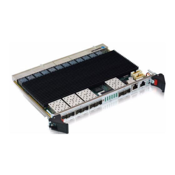
Introduction Product Overview The CP6930 is a Standard Fabric 6U CompactPCI Gigabit Ethernet Switch with 24 channels providing Layer 2 and Layer 3 switching/routing functions in a PICMG 2.16 compliant form factor. The product features 24 x 1000Base-T ports to the PICMG 2.16 backplane plus 8 x 1GbE front panel Interfaces via standard MSA SFP+ cages. - Page 16 • Metalwork compliant to PICMG® 2.0 6U/4HP (233.35 mm by 160 mm) / (20.32 mm typ.) • Optionally NV Memories can be hardware protected Note... SFP or SFP+ modules are not included with the CP6930. An appplication note with a list of modules successfully operated in the CP6930 is available upon request.
-
Page 17: General Compliances
1.2.1 Rear and Front IO Modules The IO modules provide additional GbE switch ports and out-of-band management access via RS232. With an appropriate backplane, all switch ports of the CP6930 that connect to the backplane can be accessed using the module. -
Page 18: Technical Specification
Supply voltages are: • 5.0 Volt • 3.3 Volt • 5.0 Volt IPMB_PWR Power consumption of the CP6930: • Management only (handle open): <1W • Idle (no links): 35W • Maximum (full traffic/load): 59W No external power sequencing is required. -
Page 19: Humidity
1.3.9 Shock The board is designed to meet the following requirements: • Standard • DIN/IEC 60068-2-27 • Peak Acceleration: 30 g, Shock Duration: 9 ms half sine, Recovery Time: 5 s, Shock Count: 3/direction, 6 directions CP6930 User Guide www.kontron.com... -
Page 20: Safety
• EN 300 386, Electro-Magnetic Compatibility (EMC) Requirements for Public Telecommunication Net- work Equipment; Electromagnetic Compatibility (EMC) Requirements 1.3.12 Reliability Targeted MTBF is >100,000h @ 40° C, calculations based on Bellcore/Telcordia SR-332 Issue 1. 1.3.13 WEEE Compliant to: • Directive 2002/96/EC: Waste electrical and electronic equipment CP6930 User Guide www.kontron.com... -
Page 21: Rohs
1.3.14 RoHS Compliant to: • Directive 2002/95/EC: Restriction of the use of certain hazardous substances in electrical and electronic equipment 1.3.15 Lead-free The product has to be completely lead-free concerning the production process and the components used. CP6930 User Guide www.kontron.com... -
Page 22: Software Support
Introduction 1.4 Software Support The following table contains information related to software supported by the CP6930. Table 1-2: CP6930 Software Specification CP6930 SPECIFICATIONS General • Reliable field upgrades for all software components • Dual boot images with roll-back capability • Management via SNMP and Command Line Interface •... - Page 23 • Persistent storage of configuration across restarts • Support for retrieving and installing multiple configurations • Support for startup configurations based on the cPCI SGA/GA (Shelf Geographical Address/Geographical Address), see CP6930 CLI Reference Manual, chapter „AutoIn- stall Commands“ Supported MIBS •...
- Page 24 Chapter 2 Installation www.kontron.com...
-
Page 25: Installation
Installation Installation The CP6930 has been designed for easy installation. However, the following standard precautions, installa- tion procedures, and general information must be observed to ensure proper installation and to preclude damage to the board, other system components, or injury to personnel. -
Page 26: Cp6930 Initial Installation Procedures
Installation 2.2 CP6930 Initial Installation Procedures The following procedures are applicable only for the initial installation of the CP6930 in a system. Proce- dures for standard removal and hot swap operations are found in their respective chapters. To perform an initial installation of the CP6930 in a system proceed as follows: 1. -
Page 27: Standard Removal Procedures
7. Dispose of the board as required. 2.4 Software Installation The CP6930 comes as a pre-installed system with all necessary OS, filesystem, drivers and applications fac- tory-installed with default configurations. Updating the Software with new operating system or applications or new versions is provided by a dedicated update mechanism, which is described in Chapter 4. -
Page 28: Out-Of-Band Cli Access
2.5.1.2 Fast Ethernet Serviceport The Gigabit Ethernet serviceport on the CP6930 front plate has no IP address set by default, it is necessary to assign an IP address statically or enable dhcp on the serviceport. Because the required configuration steps are done in the CLI, an initial access using the serial port is required. -
Page 29: In-Band Cli Access
The procedure for assigning an IP address to the network port is described in the following. User input is printed in bold letters. 1. Connect to serial port on the front plate (using the Kontron DB9 adapter cable) or RIO module (using a RJ45 straight cable). - Page 30 To access the CLI via Fast Ethernet networkport, open a telnet connection to the configured IP address, port It might make sense to separate the management network from the data path by setting appropriate VLANs For additional information on the system configuration, refer to the CP6930 CLI Reference Manual. CP6930 User Guide...
- Page 31 Chapter 3 Functional Description www.kontron.com...
-
Page 32: Functional Description
Functional Description The board is composed of the following building blocks: • Ethernet Infrastructure • Unit Computer and Memory • IPMI • Power Supply Figure 3-1: Functional Block Diagram CP6930 D ual Ma gnetics SFP+ 1 Dual 10GbE D ual... -
Page 33: Ethernet Infrastructure
0/16 Node Link 16 10/100/1000 Mbps 0/17 Node Link 17 10/100/1000 Mbps 0/18 Node Link 18 10/100/1000 Mbps 0/19 Node Link 19 10/100/1000 Mbps 0/20 Node Link 20 10/100/1000 Mbps 0/21 Node Link 21 10/100/1000 Mbps CP6930 User Guide www.kontron.com... - Page 34 0/33 SFP+ 6 1/10 Gbps The CP6930 supports SFP and SFP+ fabric switch uplinks to the front panel. The SFPs uplink ports are accord- ing the Small Form-factor Pluggable (SFP) Transceiver Multi-Source Agreement (MSA), Sept. 14th, 2000. Note... SFP or SFP+ modules are not included with the CP6930. An application note with a list of modules successfully operated in the CP6930 is available upon request.
-
Page 35: Unit Computer And Memory
• Real Time Clock with integrated oscillator, powered by a capacitor with up to 1 week of back up power 3.3 IPMI The CP6930 board supports an intelligent hardware management system, based on the Intelligent Platform Management Interface Specification 1.5. The hardware management system provides the ability to manage the power, cooling and interconnect needs of intelligent devices, to monitor events and to log events to a central repository intelligent FRU (Field Replaceable Unit). -
Page 36: Ipmb Interface
3.3.1 IPMB Interface The CP6930 IPMI firmware implements the two independent IPMB-0 and IPMB-1 interfaces. The IPMB-0 can be switched to a redundant mode by aggregating the physical IPMB-0 and IPMB-1 lines together to one single logical IPMB-0. -
Page 37: Write Protection Feature
Functional Description 3.4 Write Protection Feature The CP6930 supports hardware driven write protection for all non-volatile memory devices. Depending on the device, the protection is implemented either by a dedicated write protection signal, by disabling the write enable signal, or the whole interface. -
Page 38: Board Interfaces
Functional Description 3.5 Board Interfaces Figure 3-2: Front Panel of the CP6930 3.5.1 Front Panel Ports • 8x 1GBase-X uplinks (SFP connector cages), 6 of them configurable for 10GBase-X operation using SFP+ optical transceivers • SGMII support for 'Copper-SFPs' in 2 of the 8 front panel uplink ports (providing 10/100/1000Base-T modes of operation) •... -
Page 39: Table 3-6: Front Rj45 Ethernet Connector
RJ45 Female Signal Connected Description DB9 Female Number Number Request To Send Data Terminal Ready Transmit Ground Ground Front View Receive Front View Data Set Ready Clear To Send Ring Indicator (Not Used) Carrier Detect (Not Used) CP6930 User Guide www.kontron.com... -
Page 40: Front Panel Leds
• On (amber) 100Base-Tx • On (green) 1000Base-T 3.5.2.1 Health LED (Green LED) The CP6930 Switch Board supports a Health LED mounted on the front panel. The following states are possi- ble: Table 3-9: Health LED state LED state Description Normal state when board is in operation. -
Page 41: Front Panel Switches
For accessing the GbE interfaces signals on connectors J3, J4 and J5 with a rear I/O module, a special back- plane is necessary. The CP6930 is compatible with all standard 6U CompactPCI passive backplanes with rear I/O support on the system slot. -
Page 42: Table 3-11: Connector J1 Pinout
Row D Row E Row F V_5V_CPCI V_3V3_CPCI V_5V_CPCI V_5V_CPCI V_IO_CPCI V_3V3_CPCI V_5V_CPCI V_3V3_CPCI V_3V3_CPCI V_IO_CPCI V_3V3_CPCI V_3V3_CPCI V_3V3_CPCI IPMB0_SCL IPMB0_SDA V_IO_CPCI V_3V3_CPCI CPCI_BD_SEL# Key Area V_3V3_CPCI V_IO_CPCI V_3V3_CPCI CPCI_PCI_RST# V_5V_IPMB_PWR CPCI_HEALTHY# V_IO_CPCI V_5V_CPCI V_5V_CPCI V_5V_CPCI V_5V_CPCI CP6930 User Guide www.kontron.com... -
Page 43: Table 3-12: Connector J2 Pinout
3.5.5.2 J2 Connector • Geographical Address • IPMB 1 • ALERT# Table 3-12: Connector J2 Pinout Row A Row B Row C Row D Row E Row F CPCI_GA[4] CPCI_GA[3] CPCI_GA[2] CPCI_GA[1] CPCI_GA[0] IPMB1_SDA IPMB1_SCL IPMB_ALERT# CP6930 User Guide www.kontron.com... -
Page 44: Table 3-13: Connector J3 Pinout
FL_DB5+ FL_DB5- FL_DD5+ FL_DD5- FL_DA4+ FL_DA4- FL_DC4+ FL_DC4- FL_DB4+ FL_DB4- FL_DD4+ FL_DD4- FL_DA3+ FL_DA3- FL_DC3+ FL_DC3- FL_DB3+ FL_DB3- FL_DD3+ FL_DD3- FL_DA2+ FL_DA2- FL_DC2+ FL_DC2- FL_DB2+ FL_DB2- FL_DD2+ FL_DD2- FL_DA1+ FL_DA1- FL_DC1+ FL_DC1- FL_DB1+ FL_DB1- FL_DD1+ FL_DD1- CP6930 User Guide www.kontron.com... -
Page 45: Table 3-14: Connector J4 Pinout
FL_DD23- Key Area RTM_TXD# RTM_RXD# Note... RTM_TXD# (driven by CP6930) and RTM_RXD# (driven by RIO module) are the two-pin RS232 rear I/O interface. Note... Signal EWP only triggers the enhanced write protection feature as described in chapter 3.4. CP6930 User Guide... -
Page 46: Table 3-15: Connector J5 Pinout
FL_DB13+ FL_DB13- FL_DD13+ FL_DD13- FL_DA12+ FL_DA12- FL_DC12+ FL_DC12- FL_DB12+ FL_DB12- FL_DD12+ FL_DD12- FL_DA11+ FL_DA11- FL_DC11+ FL_DC11- FL_DB11+ FL_DB11- FL_DD11+ FL_DD11- FL_DA10+ FL_DA10- FL_DC10+ FL_DC10- FL_DB10+ FL_DB10- FL_DD10+ FL_DD10- FL_DA9+ FL_DA9- FL_DC9+ FL_DC9- FL_DB9+ FL_DB9- FL_DD9+ FL_DD9- CP6930 User Guide www.kontron.com... - Page 47 Chapter 4 Software Description www.kontron.com...
-
Page 48: Software Description
It is preinstalled on the system and can only be updated by a dedicated update procedure. This manual only describes bootloader, its self tests and IPMI Firmware and introduces the update procedure. For additional information of system configuration using CLI commands refer to documentation “CP6930 CLI Reference Manual”. -
Page 49: Switching
• IEEE 802.1v—Protocol-based VLANs • IEEE 802.1W—Rapid spanning tree • iEEE 802.1AB—LLDP • IEEE 802.1X—Port-based authentication • IEEE 802.3—10BASE-T • IEEE 802.3u—100BASE-T • IEEE 802.3ab—1000BASE-T • IEEE 802.3ac—VLAN tagging • IEEE 802.3ad—Link aggregation • IEEE 802.3ae—10 GbE CP6930 User Guide www.kontron.com... - Page 50 • RFC 1321—Message digest algorithm • RFC 1534—Interop. between BootP and DHCP • RFC 2030—Simple Network Time Protocol (SNTP) V4 for IPv4, IPv6, and OSI • RFC 2131—DHCP Client/Server • RFC 2132—DHCP options and BootP vendor ext. CP6930 User Guide www.kontron.com...
-
Page 51: Routing
• RFC 2328—OSPFv2 • RFC 2453—RIP v2 • RFC 3046—DHCP/BootP relay • RFC 3101—The OSPF “Not So Stubby Area” (NSSA) option • RFC 3768—Virtual Router Redundancy Protocol (VRRP) • Route redistribution across RIP and OSPF • VLAN routing CP6930 User Guide www.kontron.com... -
Page 52: Qos
• Interface trust mode: 802.1p, IP Precedence, IP DSCP, or untrusted • Interface traffic shaping rate • Minimum and maximum bandwidth per queue • Strict priority versus weighted (WRR/WDRR/WFQ) scheduling per queue • Tail drop versus Weighted Random Early Detection (WRED) queue depth management CP6930 User Guide www.kontron.com... -
Page 53: Multicast
• RFC 2674 - Q-BRIDGE-MIB: The VLAN Bridge MIB module for managing Virtual Bridged Local Area Net- works • RFC 2737 – Entity MIB version 2 • RFC 2819 - RMON Groups 1,2,3 & 9 • RFC 2863 – Interfaces Group MIB • RFC 3291 - Textual Conventions for Internet Network Addresses CP6930 User Guide www.kontron.com... -
Page 54: Routing Package Mibs
• SNMP-COMMUNITY-MIB: This MIB module defines objects to help support coexistence between SNMPv1, SNMPv2 and SNMPv3. • SNMP-FRAMEWORK-MIB: The SNMP Management Architecture MIB • SNMP-MPD-MIB: The MIB for Message Processing and Dispatching • SNMP-NOTIFICATION-MIB: The Notification MIB Module CP6930 User Guide www.kontron.com... -
Page 55: Kontron Private Mibs
• IPMI features • extended Ethernet features • SGA/GA • extended management features Kontron specific MIBs start with a “kex_”. Here‘s a list of MIBs provided (in this example for release GA 3.2) including its content: • kex_config • SNMP engine ID •... - Page 56 • OEM software part number • OEM software configuration • kex_phy • handling of PHY interfaces (SFP/XFP) • kex_ref • basic Kontron Information • kex_version • Support FPGA version of board • Support 10G PHY • Basic IPMI features supported •...
-
Page 57: Bootloader
Software Description 4.3 Bootloader On the CP6930 CPCI Ethernet Switch board, the bootloader 'u-boot' (universal bootloader) is used. The bootloader initializes the main components of the board like Unit Computer, DDR2 RAM, serial lines etc. for operation and performs a power on self test (POST). After these step have been finished, kernel and applica- tion are started from flash. -
Page 58: Bootloader Shell Options
Command script (use with “run clear_env”) that erases the U-Boot clear_env Script environment for the active image 0 – rollback when CRC check of kernel or rootfs fails (default) disable_rollback 1 – do not rollback CP6930 User Guide www.kontron.com... - Page 59 • Auto: The variable is automatically set during bootloader startup sequence. E.g. the ‘postresult’ variable stores the result of the POST. CP6930 User Guide www.kontron.com...
- Page 60 In this case the following startup message is displayed: ENV: Using default environment Any changes of the environment can be cleared using the ‘clear_env’ script (provided that ‘clear_env’ itself was not changed): => run clear_env CP6930 User Guide www.kontron.com...
-
Page 61: Ipmi Firmware
(FUM) is responsible for monitoring the PM and for managing the PM fail safe firmware upgrade pro- cess. The FUM keeps two PM Firmware code images in two external SEEPROM memories. If a failure occurs during firmware upgrade, the FUM will automatically rollback to the last known working PM firmware image. CP6930 User Guide www.kontron.com... -
Page 62: Supported Ipmi Commands
O / No Close Session 22.19 O / No Get Session Info 22.20 O / No Get AuthCode 22.21 O / No Set Channel Access 22.22 O / No Get Channel Access 22.23 O / No CP6930 User Guide www.kontron.com... - Page 63 29.1 M / Yes Get Event Receiver 29.2 M / Yes Platform Event (a.k.a. “Event Message”) 29.3 PEF and Alerting Commands Get PEF Capabilities 30.1 O / No Arm PEF Postpone Timer 30.2 O / No CP6930 User Guide www.kontron.com...
- Page 64 Get SEL Info 40.2 Storage O / Yes Get SEL Allocation Info 40.3 Storage Reserve SEL 40.4 Storage O / Yes O / Yes Get SEL Entry 40.5 Storage Add SEL Entry 40.6 Storage O / Yes CP6930 User Guide www.kontron.com...
-
Page 65: Table 4-5: Hpm.1 Commands
HPM.1 Get Upgrade Status HPM.1 Activate Firmware HPM.1 Query Self-Test Results HPM.1 Query Rollback Status HPM.1 Initiate Manual Rollback HPM.1 4.4.1.2 Kontron OEM Commands and Extensions Table 4-6: Kontron OEM Commands Command NetFn OemApSetNvParam OemApFormatStorage OemApRefreshExternUpdatedSensor OemApSetManufacturingDate OemApGetManufacturingDate OemApGetReleaseInfo OemApGetFirmwareCapabilities... - Page 66 Product ID, LS Byte first 11..12 Returned as 6A5h Auxiliary Firmware Revision Information Byte 13: Sensor Data Record Version 13..16 Byte 14: Slot ID Byte 15: Firmware Maintenance Revision Byte 16: Unused Device ID, returned as 0fh. CP6930 User Guide www.kontron.com...
- Page 67 OemApFormatStorage NetFn OemApFormatStorage OEM = 3Eh Byte Data Field Pass Code 0: ~’K’ (0xBA) Pass Code 1: ~’o’ (0x90) Request data 1...4 Pass Code 2: ~’n’ (0x91) Pass Code 3: ~’t’ (0x8B) Response data Completion Code CP6930 User Guide www.kontron.com...
- Page 68 OEM = 3Eh Byte Data Field Pass Code 0: ~’K’ (0xBA) Pass Code 1: ~’o’ (0x90) Request data 1...4 Pass Code 2: ~’n’ (0x91) Pass Code 3: ~’t’ (0x8B) Completion Code Response data 2...4 Manufacturing Date CP6930 User Guide www.kontron.com...
- Page 69 OEM = 30h Byte Data Field Pass Code 0: ~’S’ Pass Code 1: ~’1’ Request data Pass Code 2: ~’7’ Pass Code 3: ~’0’ Pass Code 4: ~’1’ Completion Code. Response data 2..19 Firmware capabilities vector CP6930 User Guide www.kontron.com...
- Page 70 Pass Code 2: ~’7’ Pass Code 3: ~’0’ Request data Pass Code 4: ~’1’ Action: 00h: memory erase one time 01h: init memory erase (short term) 02h: init memory erase (long term) Response data Completion Code. CP6930 User Guide www.kontron.com...
-
Page 71: Board Sensors
(SDRR) of the whole rack if the SDRR is generated. The generation of the SDRR has always to be done new after adding or subtracting any board to or from the rack. For OEM (Kontron) specific sensor types and reading types in the following table please refer to the next chapter. - Page 72 22 / Icc3.3vCPCI 03h (Current) Event Type: 01h (Threshold) 23 / Vcc3.3vCPLD 02h (Voltage) Event Type: 01h (Threshold) 24 / Vcc3.3vSUS 02h (Voltage) Event Type: 01h (Threshold) 25 / Vcc3.3v 02h (Voltage) Event Type: 01h (Threshold) CP6930 User Guide www.kontron.com...
- Page 73 Offset 0: Fault status (SFP not present) Offset 1: Identify Status (SFP present) Event Type: 6Fh (Sensor Specific) 42 / SFP-32 21h ( Slot/connector) Offset 0: Fault status (SFP not present) Offset 1: Identify Status (SFP present) CP6930 User Guide www.kontron.com...
-
Page 74: Table 4-7: Sensor List
Sensor Type (CODE) Event Type Code / Event Offsets string Event Type: 6Fh (Sensor Specific) 43 / POST Value C6h (Kontron OEM ) Offset 0Eh: POST Error Event Data 2: POST code Event Type: 6Fh (Sensor Specific) 44 / Boot Error 1Eh (Boot Error) Refer to IPMI v1.5... -
Page 75: Board Fru Information
FRU Board Info Area • Manufacturing date / time • Board manufacturer: “Kontron” • Board Product Name: “ CP6930” • Board Serial Number : “1234567890” • Board Part Number: “S1701” • FRU File ID: “FRU-S1701-xx” (xx - template file version) CP6930 User Guide www.kontron.com... -
Page 76: Firmware Administration
Shown values are examples. 4.5 Firmware Administration A running CP6930 system requires – after the bootloader has passed control to the kernel – the kernel itself, the root file system (initrd) and the FASTPATH switching application. These software components make up the CP6930 firmware. -
Page 77: Updating Firmware
The CLI commands described below are executed in the privileged mode of the CLI hierarchy, which is entered by executing the ‘enable’ command. Please refer to the “CP6930 CLI Reference Manual“ for more information regarding the CLI commands and the way to use them. - Page 78 Software Description When performing a firmware update, the software package is loaded from a remote TFTP server. A software update of the CP6930 CPCI Switch is done by performing the following steps: 1. Prepare network access of the board 2. Log in to the privileged exec mode of the CLI of the board 3.
-
Page 79: Updating Ipmi
The IPMI firmware package file is provided in HPM.1 format and is stored in the data/update directory of the release directory tree. (Ethernet Fabric) #copy tftp://192.168.50.5/cp6930-ipmi-GA-2.00.hpm nvram:ipmi Flashing a new IPMI firmware will disable the IPMI Controller for some minutes. - Page 80 Chapter 5 Thermal Considerations www.kontron.com...
-
Page 81: Thermal Considerations
The CP6930 has six temperature sensors which ensure operation within the specified temperature limits. The sensors are accessible via the Peripheral Manager. Although temperature sensing information is made avail- able to the PM, the CP6930 itself does not provide any active means of temperature regulation. The following temperatures are measured by the Peripheral Manager. -
Page 82: Thermal Regulation
Temperature Sensor Location 5.2 Thermal Regulation When developing applications using the CP6930, the system integrator must be aware of the overall system thermal requirements. A system chassis must be provided which satisfy these requirements. Measurements proofed that operation in worst case conditions (maximum ambient temperature of 68°C under maximum load) with sufficient air flow (i.e. -
Page 83: Airflow
Maximum PCB3 temperature versus airflow 5.3 Airflow In order to allow system integrators to optimize environmental conditions for the CP6930, airflow measure- ments were performed. The pressure drop between inlet and outlet was measured and is shown in the follow- ing graph. -
Page 84: Figure 5-4: Airflow Distribution By Test Section
Thermal Considerations The area between the front panel and the backplane connectors is divided into five zones. The following dia- gram shows the airflow distribution across those zones. Figure 5-4: Airflow Distribution by Test Section CP6930 User Guide www.kontron.com... - Page 85 Chapter 6 Chapter 6 Power Considerations www.kontron.com...
-
Page 86: Power Considerations
6.1.1 Baseboard The CP6930 baseboard itself has been designed for optimal power input and distribution. Still it is necessary to observe certain criteria essential for application stability and reliability. The board is supplied by the 3.3V and the 5.0V from the backplane. All supply voltages from the backplane are enabled with a predefined ramp-up time. -
Page 87: Power Supply Units
An ATX power supply unit should be able to provide at least three times as much power as the entire system requires. As the design of the CP6930 has been optimized for minimal power consumption, the power supply unit shall be stable even without minimum load. -
Page 88: Table 6-2: Input Voltage Characteristics
For example, if the +5V begins to decrease, +3.3V must decrease accordingly. This is required in order to preclude cross currents within the CP6930. Failure to comply with above may result in damage to the board or improper system operation. -
Page 89: Power Consumption
57.6 6.3 Start-up Currents The start-up currents of the CP6930 during the first 2-3 seconds after power has been applied (power-on or hot-swap insertion) are less than the maximum currents given in Table 6-3 for each of the variants. CP6930 User Guide... -
Page 90: Getting Help
Appendix A Getting Help www.kontron.com... -
Page 91: Returning Defective Merchandise
Tel.: +49 (0) 8341 803 333 Fax: (450) 437-8053 Fax: +49 (0) 8341 803 339 If you have any questions about Kontron, our products, or services, visit our Web site at: www.kontron.com You also can contact us by E-mail at: North America: support@ca.kontron.com EMEA: support-kom@kontron.com... -
Page 92: When Returning A Unit
• E-mail • Send us an e-mail at: RMA@ca.kontron.com in North America or at: orderprocessing@kontron- modular.com in EMEA. In the e-mail, you must include your name, your company name, your ad- dress, your city, your postal/zip code, your phone number, and your e-mail. You must also include the serial number of the defective product and a description of the problem.
Need help?
Do you have a question about the CP6930 and is the answer not in the manual?
Questions and answers