Sign In
Upload
Manuals
Brands
Kontron Manuals
Computer Hardware
CP6003-RA/RC
Kontron CP6003-RA/RC Manuals
Manuals and User Guides for Kontron CP6003-RA/RC. We have
1
Kontron CP6003-RA/RC manual available for free PDF download: User Manual
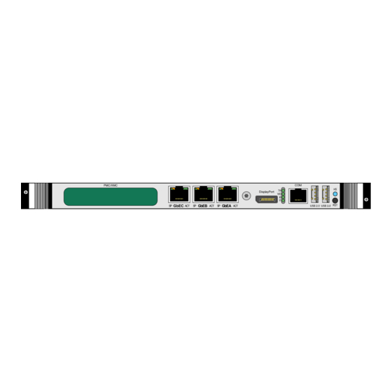
Kontron CP6003-RA/RC User Manual (138 pages)
Rugged 6U CompactPCI Processor Board based on the 2nd Generation Intel Core i7 Processor with the Intel QM67 Express Chipset
Brand:
Kontron
| Category:
Computer Hardware
| Size: 1.2 MB
Table of Contents
Imprint
2
Disclaimer
2
Table of Contents
3
List of Tables
9
List of Figures
13
Proprietary Note
15
Trademarks
15
Environmental Protection Statement
15
Explanation of Symbols
16
For Your Safety
17
High Voltage Safety Instructions
17
Special Handling and Unpacking Instructions
17
General Instructions on Usage
18
Two Year Warranty
19
Introduction
21
Board Overview
23
CP6003-RA Board-Specific Information
24
CP6003-RC Board-Specific Information
25
System Expansion Capabilities
26
PMC/XMC Module (CP6003-RA)
26
Conductive-Cooled PMC/XMC Module (CP6003-RC)
26
SATA Flash Module
26
Rear I/O Module
26
Version Comparison
26
Board Diagrams
27
Functional Block Diagram
27
CP6003-RA/RC Functional Block Diagram
27
Front Panel
28
CP6003-RA Front Panel
28
Board Layout
29
CP6003-RA Board Layout - Top View
29
CP6003-RC Board Layout - Top View
30
CP6003-RA Board Layout - Bottom View
31
CP6003-RC Board Layout - Bottom View
32
Technical Specification
33
CP6003-RA/RC Main Specifications
33
Standards
40
Standards for the CP6003-RA
40
Standards for the CP6003-RC
41
Related Publications
42
Functional Description
43
Processor
45
Memory
46
Intel® QM67 Express Chipset
46
Features of the Processors Supported on the CP6003-RA/RC
46
Timer
47
Watchdog Timer
47
Battery
47
Reset
47
Flash Memory
48
SPI Boot Flash for Uefi BIOS
48
Serial ATA Flash Module (Optional)
48
Trusted Platform Module 1.2 (on Request)
48
Board Interfaces
49
Onboard and Front Panel Leds
49
IPMI Leds and Hot Swap LED
49
IPMI Leds and Hot Swap LED Function
49
Watchdog LED and Temperature Status LED
50
Watchdog LED and Temperature Status LED Function
50
Debug Leds
51
Debug Leds Function
51
POST Code Sequence
52
POST Code Example
52
DIP Switches SW1, SW2 and SW3 (CP6003-RA)
53
Configuration Resistors (CP6003-RC)
53
DIP Switch SW1 Function
53
DIP Switch SW2 Function
53
DIP Switch SW3 Function
53
USB Interfaces
54
USB Connectors J6 and J7
54
Integrated Graphics Controller
54
Graphics Memory Usage
55
Displayport Interface (CP6003-RA)
55
Displayport Connector J9 Pinout
55
Displayport Connector J9
55
COM Ports
56
Gigabit Ethernet
57
Gigabit Ethernet Port Mapping
57
Serial ATA Interface
58
GPI and GPO Signals
58
Gbe Connectors J10, J11 and J12
58
PMC Interface
59
PMC Connectors J15, J16, J17 and J18
60
2.10.10.1 PMC Connectors J15, J16, J17 and J18 Pinout
61
PMC Connectors J16 and J18 Pinout
61
PMC Connectors J15 and J17 Pinout
62
XMC Interface
63
XMC Connector J14
63
Debug Interface
64
Compactpci Interface
64
2.10.13.1 Board Functionality When Installed in System Slot
64
Board Functionality When Installed in Peripheral Slot
65
Packet Switching Backplane (PICMG 2.16)
65
2.10.13.4 Hot Swap Support
65
Power Ramping
65
Precharge
65
Handle Switch (CP6003-RA)
65
2.10.13.8 ENUM# Interrupt
65
Hot Swap LED (CP6003-RA)
65
Compactpci Bus Connector
66
2.10.14.1 Compactpci Connector Keying
66
2.10.14.2 Compactpci Connectors J1 and J2 Pinout
67
Compactpci Bus Connector J1 System Slot Pinout
67
Compactpci Bus Connector J1 Peripheral Slot Pinout
68
2.10.14.3 Compactpci Rear I/O Connectors J3-J5 and Pinout
71
Compactpci Rear I/O Connector J3 Pinout
71
Compactpci Rear I/O Connector J3 Signals
72
Compactpci Rear I/O Connector J4 Pinout
73
Compactpci Rear I/O Connector J5 Pinout
74
Compactpci Rear I/O Connector J5 Signals
75
Installation
77
Safety Requirements
79
CP6003-RA Installation
80
CP6003-RA Initial Installation Procedures
80
Standard Removal Procedures
81
Hot Swap Procedures
82
System Master Hot Swap
82
Peripheral Hot Swap Procedure
82
Installation of CP6003-RA Peripheral Devices
84
USB Device Installation
84
SATA Flash Module Installation
84
Connecting a Peripheral Device to the CP6003-RA
84
PMC/XMC Module Installation
85
Rear I/O Device Installation
85
Battery Replacement
85
CP6003-RC Installation
86
Initial Installation Procedures
86
Standard Removal Procedures
87
Hot Swap Procedures
88
System Master Hot Swap
88
CP6003-RC Hot Swap Procedure
88
Installation of CP6003-RC Peripheral Devices
91
USB Device Installation
91
Rear I/O Device Installation
91
Connecting a Peripheral Device to the CP6003-RC
91
Ccpmc/Conduction-Cooled XMC Module Installation
92
Software Installation
92
Configuration
93
DIP Switches SW1, SW2 and SW3 Configuration (CP6003-RA)
95
DIP Switch SW1 for Compactpci Interface Configuration
95
DIP Switch SW2 for PMC Interface Configuration
95
DIP Switches SW1, SW2 and SW3 (CP6003-RA)
95
DIP Switch SW3 for Boot Configuration
96
Configuration Resistors (CP6003-RC)
97
Configuration Resistors
97
Configuration Resistors' Settings
97
Jumper Description
98
COMB Termination Jumper Settings
98
JP2 Jumper Setting for RS-422 TXD Termination (COMB)
98
JP3 Jumper Setting for RS-422 RXD Termination (COMB)
98
I/O Address Map
99
CP6003-RA/RC-Specific Registers
100
Status Register 0 (STAT0)
100
Status Register 1 (STAT1)
101
Control Register 0 (CTRL0)
102
Control Register 1 (CTRL1)
103
Device Protection Register (DPROT)
104
Reset Status Register (RSTAT)
105
Board Interrupt Configuration Register (BICFG)
106
Status Register 2 (STAT2)
107
Board ID High Byte Register (BIDH)
107
Board and PLD Revision Register (BREV)
108
Geographic Addressing Register (GEOAD)
108
Watchdog Timer Control Register (WTIM)
109
Watchdog Timer Control Register (WTIM)
110
Board ID Low Byte Register (BIDL)
111
LED Configuration Register (LCFG)
112
LED Control Register (LCTRL)
113
General Purpose Output Register (GPOUT)
114
General Purpose Input Register (GPIN)
114
IPMI Keyboard Controller Style Interface
114
Power Considerations
115
System Power
117
CP6003-RA/RC Baseboard
117
Backplane
117
Maximum Input Power Voltage Limits
117
DC Operational Input Voltage Ranges
117
Power Supply Units
118
Start-Up Requirement
118
Power-Up Sequence
118
Tolerance
118
Input Voltage Characteristics
118
Regulation
119
Power Consumption of CP6003-RA/RC
119
Uefi Shell Mode
121
Win. XP with Processor and Graphics in Idle State
121
Power Consumption of the CP6003-RA/RC Accessories
122
Power Consumption Per Gigabit Ethernet Port
122
Maximum Power Consumption of PMC Modules
122
Power Consumption of CP6003-RA/RC Accessories
122
Maximum Power Consumption of XMC Modules
123
Thermal Considerations
125
Board Internal Thermal Monitoring
127
Processor Thermal Monitoring
127
Digital Thermal Sensor (DTS)
127
Adaptive Thermal Monitor
128
Frequency/Svid Control
128
Clock Modulation
128
Catastrophic Cooling Failure Sensor
129
Chipset Thermal Monitor Feature
129
External Thermal Regulation for CP6003-RA
129
Operational Limits for the CP6003-RA
131
CP6003-RA with Intel® Quad-Core I7-2715QE (SV), 2.1 Ghz
131
CP6003-RA with Intel® Dual-Core I7-2655LE (LV), 2.2 Ghz
131
Thermal Characteristics for the CP6003-RC
132
Position of the Reference Point on the CP6003-RC
132
Maximum Reference Point Temperature with Core™ I7-2715QE
133
Maximum Reference Point Temperature with Core™ I7-2655LE
133
Peripherals
134
SATA Flash Module
137
Technical Specifications
137
SATA Flash Module Main Specifications
137
SATA Flash Module Layout
138
SATA Flash Module Layout (Bottom View)
138
Advertisement
Advertisement
Related Products
Kontron CP6005-SA
Kontron CP6005X-SA
Kontron CP6003-SA
Kontron CP6002
Kontron CP6007-SA
Kontron CP6007-RA
Kontron CP6012
Kontron CP6016
Kontron CP6-BP8-H110
Kontron CP6-BP4-PB-RIO
Kontron Categories
Computer Hardware
Motherboard
Server
Desktop
PCI Card
More Kontron Manuals
Login
Sign In
OR
Sign in with Facebook
Sign in with Google
Upload manual
Upload from disk
Upload from URL