
Subscribe to Our Youtube Channel
Related Manuals for Kontron CP6002


Summary of Contents for Kontron CP6002
- Page 1 » User Guide « CP6002 6U CompactPCI Processor Board based on the Intel® Core™ i7 Processor with the Intel® QM57 Chipset Doc. ID: 1036-6431, Rev. 2.0 July 4, 2011 If it’s embedded, it’s Kontron.
-
Page 2: Imprint
Disclaimer Copyright © 2011 Kontron AG. All rights reserved. All data is for information purposes only and not guaranteed for legal purposes. Information has been carefully checked and is believed to be accurate; however, no responsibility is assumed for inaccuracies. Kontron and the Kontron logo and all other trademarks or registered trademarks are the property of their respective own- ers and are recognized. -
Page 3: Table Of Contents
1.3 System Expansion Capabilities ............... 1 - 5 1.3.1 PMC/XMC Module ................1 - 5 1.3.2 CP6002-MK2.5SATA Assembly Kit ..........1 - 5 1.3.3 Serial ATA Flash Module ..............1 - 5 1.4 Version Comparison ................1 - 5 1.5 Board Diagrams ..................1 - 5 1.5.1... - Page 4 2.8.2 Serial ATA Flash Module (optional) ..........2 - 6 2.8.3 CompactFlash Socket (CP6002-R1 and CP6002-R1-MC) .....2 - 6 2.9 Trusted Platform Module 1.2 (On Request) ..........2 - 6 2.10 Board Interfaces ..................2 - 7 2.10.1 Front Panel LEDs ................2 - 7 2.10.1.1...
- Page 5 3.4.1 System Master Hot Swap ............... 3 - 6 3.4.2 Peripheral Hot Swap Procedure ............. 3 - 6 3.5 Installation of CP6002 Peripheral Devices ..........3 - 9 3.5.1 USB Device Installation ..............3 - 11 3.5.2 SATA Flash Module Installation ............ 3 - 11 3.5.3...
- Page 6 Preface CP6002 4.3 I/O Address Map ..................4 - 6 4.4 CP6002-Specific Registers ..............4 - 7 4.4.1 Status Register 0 (STAT0) ...............4 - 7 4.4.2 Status Register 1 (STAT1) ...............4 - 8 4.4.3 Control Register 0 (CTRL0) ............4 - 9 4.4.4 Control Register 1 (CTRL1) ............4 - 9...
- Page 7 CP6002 Preface 5.2.1 Power Consumption of the CP6002 Accessories ......5 - 8 5.2.2 Power Consumption of the Gigabit Ethernet Controller ....5 - 8 5.3 Start-Up Currents of the CP6002 ............5 - 8 5.4 Maximum Power Consumption of PMC/XMC Modules ......5 - 9 Thermal Considerations ............
- Page 8 Preface CP6002 This page has been intentionally left blank. Page viii ID 1036-6431, Rev. 2.0...
-
Page 9: List Of Tables
Standards for the CP6002 ............... 1 - 19 Related Publications ................1 - 20 Features of the Processors Supported on the CP6002 ......2 - 4 IPMI and Hot Swap LEDs Function ............2 - 7 Watchdog and Temperature Status LEDs Function ........2 - 8 DIP Switch SW1 Function ................. -
Page 10: Timer
CP6002 with Win. XP and Processor and Graphics in Idle State ....5 - 7 CP6002 with Win. XP and Max. Proc. Workload and Graph. in Idle State.. 5 - 7 CP6002 with Win. XP and Maximum Processor and Graphics Workload .. 5 - 7 Power Consumption of CP6002 Accessories .......... - Page 11 CP6002 Preface A-2 Board-to-Board Connector J1 Pinout ............A - 6 A-3 SATA Connector J2 Pinout ................ A - 7 B-1 SATA Flash Module Main Specifications ........... B - 3 ID 1036-6431, Rev. 2.0 Page xi...
- Page 12 Preface CP6002 This page has been intentionally left blank. Page xii ID 1036-6431, Rev. 2.0...
-
Page 13: List Of Figures
DIP Switch SW1 ..................4 - 3 DIP Switches SW2 and SW3 ..............4 - 4 CP6002-R1 and CP6002-R1-MC with i7-610E, 2.53 GHz ...... 6 - 8 CP6002-R1 and CP6002-R1-MC with i7-620LE, 2.0 GHz ....... 6 - 8 CP6002-R2-MC with i7-620LE, 2.0 GHz ..........6 - 9 CP6001-EXT-SATA Functional Block Diagram ........ - Page 14 Preface CP6002 This page has been intentionally left blank. Page xiv ID 1036-6431, Rev. 2.0...
-
Page 15: Proprietary Note
Kontron without further notice. Trademarks Kontron, the PEP logo and, if occurring in this manual, “CXM” are trademarks owned by Kontron, Kaufbeuren (Germany). In addition, this document may include names, company logos and trademarks, which are registered trademarks and, therefore, proprietary to their respective owners. -
Page 16: Explanation Of Symbols
Preface CP6002 Explanation of Symbols Caution, Electric Shock! This symbol and title warn of hazards due to electrical shocks (> 60V) when touching products or parts of them. Failure to observe the pre- cautions indicated and/or prescribed by the law may endanger your life/health and/or result in damage to your material. -
Page 17: For Your Safety
However, the life expectancy of your product can be drastically reduced by improper treatment during unpacking and installation. Therefore, in the interest of your own safety and of the correct operation of your new Kontron product, you are requested to conform with the following guidelines. -
Page 18: General Instructions On Usage
CP6002 General Instructions on Usage In order to maintain Kontron’s product warranty, this product must not be altered or modified in any way. Changes or modifications to the device, which are not explicitly approved by Kontron and described in this manual or received from Kontron’s Technical Support as a special handling instruction, will void your warranty. -
Page 19: Two Year Warranty
As a result, the products are sold “as is,” and the responsibility to ensure their suitability for any given task remains that of the purchaser. In no event will Kontron be liable for direct, indirect or consequential damages resulting from the use of our hardware or software products, or documentation, even if Kontron were advised of the possibility of such claims prior to the purchase of the product or during any period since the date of its purchase. - Page 20 Preface CP6002 This page has been intentionally left blank. Page xx ID 1036-6431, Rev. 2.0...
-
Page 21: Introduction
CP6002 Introduction Chapter Introduction ID 1036-6431, Rev. 2.0 Page 1 - 1... - Page 22 Introduction CP6002 This page has been intentionally left blank. Page 1 - 2 ID 1036-6431, Rev. 2.0...
-
Page 23: Board Overview
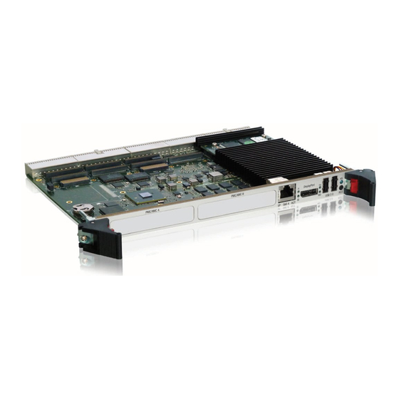
2.5" SATA HDD/SSD and provides two Gigabit Ethernet ports, one VGA (CRT) port, one COM port and two USB ports on the front panel. The CP6002-R1-MC and CP6002-R2-MC provide one Gigabit Ethernet port, one DisplayPort and two USB ports on the front panel. -
Page 24: Board-Specific Information
CP6002, please contact Kontron. Board-Specific Information The CP6002 is a CompactPCI single-board computer based on the Intel® Core™ i7 processor and specifically designed for use in highly integrated platforms with solid mechanical interfacing for a wide range of industrial environment applications. -
Page 25: System Expansion Capabilities
1.3.3 Serial ATA Flash Module The CP6002 provides support for up to 32 GB of Serial ATA Flash memory in combination with an optional Serial ATA Flash module, which is connected to an onboard extension connector. For further information concerning the Serial ATA Flash module, please refer to Appendix B. -
Page 26: Functional Block Diagram
Introduction CP6002 1.5.1 Functional Block Diagram Figure 1-1: CP6002 Functional Block Diagram Reset Page 1 - 6 ID 1036-6431, Rev. 2.0... -
Page 27: Front Panels
CP6002 Introduction 1.5.2 Front Panels Figure 1-2: CP6002 Front Panels Legend: IPMI LEDs: I0/I1 (green): Indicate the software sta- tus of the IPMI controller Status LEDs: WD (green): Watchdog Status TH (green): Temperature Status HS (blue): Hot Swap Control Ethernet LEDs on CP6002-R1:... -
Page 28: Board Layout
Introduction CP6002 1.5.3 Board Layout Figure 1-3: CP6002-R1 Board Layout – Top View PMC A/ Battery (P15) XMC A (Jn1 Logic (Jn2) CompactFlash Socket (Jn3) Intel ® QM57 Mag. (Jn4) Mag. HDD/SSD DDR3 Memory GbE B CP6001- EXT-SATA LEDs Module... - Page 29 CP6002 Introduction Figure 1-4: CP6002-R1-MC Board Layout – Top View PMC A/ Battery (P15) XMC A (Jn1 Logic (Jn2) CompactFlash Socket (Jn3) Intel ® QM57 Mag. (Jn4) Mag. PMC B/ (Jn1 XMC B (P15) DDR3 Memory (Jn2) (Jn3) GbE A IPMI LEDs Intel ®...
- Page 30 Introduction CP6002 Figure 1-5: CP6002-R2-MC Board Layout – Top View PMC A/ Battery XMC A (Jn1 (P15) Logic (Jn2) (Jn3) Intel ® QM57 Mag. (Jn4) Mag. PMC B/ (Jn1 XMC B (P15) DDR3 Memory (Jn2) (Jn3) GbE A IPMI LEDs Intel ®...
- Page 31 CP6002 Introduction Figure 1-6: CP6002 Board Layout – Bottom View Temp1 Super DLED 0 DLED 1 DLED 2 DLED 3 DDR3 Memory PCIe-to- PCI-X Bridge PCIe-to- PCI-X Bridge ID 1036-6431, Rev. 2.0 Page 1 - 11...
-
Page 32: Technical Specification
DMI and FDI interfaces to the Intel® QM57 chipset • Two x8 PCI Express 2.0 ports operating at 2.5 GT/s • Please contact Kontron for further information concerning the suitability of other Intel processors for use with the CP6002. Memory Main Memory: Up to 8 GB, dual-channel DDR3 SDRAM memory with ECC running at •... - Page 33 • Compliant with the Packet Switching Specification PICMG 2.16. When installed in a peripheral slot, the CP6002 is isolated from the CompactPCI bus. It receives power from the backplane and supports rear I/O and, if the system supports it, packet switching (in this case up to two channels of Gigabit Ethernet).
-
Page 34: System Master Hot Swap
The CP6002 supports System Master hot swap functionality and application- dependent hot swap functionality when used in a peripheral slot. When used as a System Master, the CP6002 supports individual clocks for each slot and the ENUM signal handling is in compliance with the PICMG 2.1 Hot Swap Specification. - Page 35 CP6002 Introduction Table 1-2: CP6002 Main Specifications (Continued) FEATURES SPECIFICATIONS Mass Storage CompactFlash (CP6002-R1 and CP6002-R1-MC): CompactFlash socket for type I and II CompactFlash cards (DMA • capable true IDE mode) The CompactFlash is always configured as IDE master •...
- Page 36 Ethernet LEDs Gigabit Ethernet Status on CP6002-R1: ACT (green): Ethernet Link/Activity • SPEED (green): Ethernet Speed • Gigabit Ethernet Status on CP6002-R1-MC and CP6002-R2-MC: ACT (green): Ethernet Link/Activity • SPEED (green / orange/off): Ethernet Speed • Watchdog Timer Software-configurable, two-stage Watchdog with programmable timeout •...
- Page 37 SPI Flash control, and boot order configuration Operating Systems The board is offered with various Board Support Packages including Windows and Linux operating systems. For further information concerning the operating systems available for the CP6002, please contact Kontron. ID 1036-6431, Rev. 2.0 Page 1 - 17...
- Page 38 233.35 mm x 160 mm Board Weight CP6002-R1: 500 g (with heat sink but without mezzanine cards) CP6002-R1-MC: 500 g (with heat sink but without mezzanine cards) CP6002-R2: 720 g (with heat sink but without mezzanine cards) Page 1 - 18...
-
Page 39: Standards
Customers desiring to perform further environmental testing of Kontron prod- ucts must contact Kontron for assistance prior to performing any such testing. This is necessary, as it is possible that environmental testing can be destructive when not performed in accordance with the applicable specifications. -
Page 40: Related Publications
Unified Extensible Firmware Interface (uEFI) Specification, Version 2.1 All Kontron products Product Safety and Implementation Guide, ID 1021-9142 Kontron CP6002 uEFI BIOS User Guide, ID 1039-1612 CP6002 IPMI Firmware User Guide: ID 1039-1613 Page 1 - 20 ID 1036-6431, Rev. 2.0...
Need help?
Do you have a question about the CP6002 and is the answer not in the manual?
Questions and answers