
Related Manuals for Kontron CP6016


Summary of Contents for Kontron CP6016
- Page 1 sales@artisantg.com artisantg.com (217) 352-9330 | Visit our website - Click HERE...
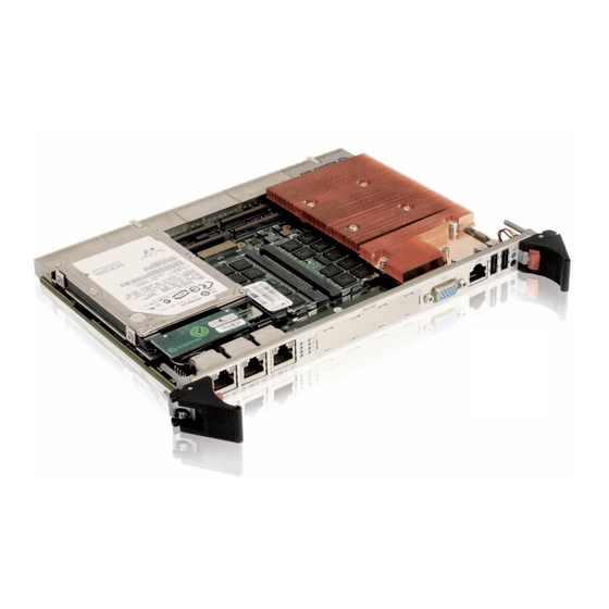
- Page 2 » User Guide « CP6016 6U CompactPCI Processor Board based on the Intel® Core™2 Duo Processor with the Intel® 5100 MCH Chipset Doc. ID: 1022-3074, Rev. 2.0 July 23, 2009 If it’s embedded, it’s Kontron.
-
Page 3: Imprint
Disclaimer Copyright © 2009 Kontron AG. All rights reserved. All data is for information purposes only and not guaranteed for legal purposes. Information has been carefully checked and is believed to be accurate; however, no responsibility is assumed for inaccuracies. Kontron and the Kontron logo and all other trademarks or registered trademarks are the property of their respective own- ers and are recognized. -
Page 4: Table Of Contents
1.3.1 PMC Module ................... 1 - 5 1.3.2 XMC Module ................... 1 - 5 1.3.3 CP6016-MK2.5SATA Assembly Kit ..........1 - 5 1.3.4 USB 2.0 NAND Flash Module ............1 - 5 1.4 Board Diagrams ..................1 - 5 1.4.1 Functional Block Diagram ............... - Page 5 Preface CP6016 Functional Description ............2 - 3 2.1 CPU, Memory and Chipset ..............2 - 3 2.1.1 CPU ....................2 - 3 2.1.2 Memory ...................2 - 4 2.1.3 Intel® 5100 Memory Controller Hub Chipset ........2 - 4 2.1.4 Intel® 5100 Memory Controller Hub ..........2 - 4 2.1.5...
- Page 6 3.4.1 System Master Hot Swap ............... 3 - 6 3.4.2 Peripheral Hot Swap Procedure ............. 3 - 6 3.5 Installation of CP6016 Peripheral Devices ..........3 - 8 3.5.1 USB Device Installation ..............3 - 8 3.5.2 USB 2.0 NAND Flash Module Installation ........3 - 9 3.5.3...
- Page 7 Configuration ................4 - 3 4.1 DIP Switches SW1, SW2 and SW3 Configuration ........4 - 3 4.2 Jumper Description ..................4 - 4 4.3 I/O Address Map ..................4 - 5 4.4 CP6016-Specific Registers ..............4 - 6 4.4.1 Status Register 0 (STAT0) ...............4 - 6 4.4.2 Status Register 1 (STAT1) ...............4 - 7...
- Page 8 Regulation ................5 - 5 5.2 Power Consumption ................5 - 6 5.2.1 Power Consumption of the CP6016 Accessories ......5 - 8 5.2.2 Power Consumption of the Gigabit Ethernet Controllers ....5 - 8 5.3 Start-Up Currents of the CP6016 ............5 - 8 5.4 Power Available for PMC/XMC Devices ..........
- Page 9 Preface CP6016 A.5 Module Interfaces ................... A - 6 A.5.1 Board-to-Board Connectors J1 and J3 ........... A - 6 A.5.2 SATA Connector J2 ................ A - 7 Page viii ID 1022-3074, Rev. 2.0...
-
Page 10: List Of Tables
CP6016 Preface List of Tables CP6016 Main Specifications ..............1 - 10 Standards ....................1 - 16 Additional Standards for Boards Ordered with Ruggedized Service ..1 - 17 Related Publications ................1 - 17 Memory Options Utilizing SO-RDIMM Sockets ......... 2 - 4 IPMI and Hot Swap LEDs Function ............ - Page 11 Preface CP6016 2-29 CompactPCI Rear I/O Connector J4 Pinout ..........2 - 31 2-31 CompactPCI Rear I/O Connector J5 Signals ........... 2 - 32 2-30 CompactPCI Rear I/O Connector J5 Pinout ..........2 - 32 2-32 Processor, Chipset and General Board Supervision ........ 2 - 36 2-33 Various BMC/SMC Sensors ..............
- Page 12 Preface Power Consumption: CP6016 in EFI Shell Mode ........5 - 7 Power Consumption: CP6016 with Linux®/Windows® XP in IDLE Mode 5 - 7 Power Consumption: CP6016 with Linux®/Windows® XP, Memory Test . 5 - 7 Power Consumption: CP6016 TDP at 75% ..........5 - 7 Power Consumption: CP6016 TDP at 100% ..........
- Page 13 Preface CP6016 This page has been intentionally left blank. Page xii ID 1022-3074, Rev. 2.0...
-
Page 14: List Of Figures
Temperature Sensor Placement (CP6016 Top View) ......6 - 3 Oper. Limits for the CP6016 Running at 2.53 GHz (Full Clock Speed) .. 6 - 8 Oper. Limits for the CP6016 Running at 2.0 GHz (Red. Clock Speed) ..6 - 8 CP6001-EXT-SATA Functional Block Diagram ........ - Page 15 Preface CP6016 This page has been intentionally left blank. Page xiv ID 1022-3074, Rev. 2.0...
-
Page 16: Proprietary Note
Kontron without further notice. Trademarks Kontron, the PEP logo and, if occurring in this manual, “CXM” are trademarks owned by Kontron, Kaufbeuren (Germany). In addition, this document may include names, company logos and trademarks, which are registered trademarks and, therefore, proprietary to their respective owners. -
Page 17: Explanation Of Symbols
Preface CP6016 Explanation of Symbols Caution, Electric Shock! This symbol and title warn of hazards due to electrical shocks (> 60V) when touching products or parts of them. Failure to observe the pre- cautions indicated and/or prescribed by the law may endanger your life/health and/or result in damage to your material. -
Page 18: For Your Safety
However, the life expectancy of your product can be drastically reduced by improper treatment during unpacking and installation. Therefore, in the interest of your own safety and of the correct operation of your new Kontron product, you are requested to conform with the following guidelines. -
Page 19: General Instructions On Usage
CP6016 General Instructions on Usage In order to maintain Kontron’s product warranty, this product must not be altered or modified in any way. Changes or modifications to the device, which are not explicitly approved by Kontron and described in this manual or received from Kontron’s Technical Support as a special handling instruction, will void your warranty. -
Page 20: Two Year Warranty
As a result, the products are sold “as is,” and the responsibility to ensure their suitability for any given task remains that of the purchaser. In no event will Kontron be liable for direct, indirect or consequential damages resulting from the use of our hardware or software products, or documentation, even if Kontron were advised of the possibility of such claims prior to the purchase of the product or during any period since the date of its purchase. - Page 21 Preface CP6016 This page has been intentionally left blank. Page xx ID 1022-3074, Rev. 2.0...
-
Page 22: Introduction
CP6016 Introduction Chapter Introduction ID 1022-3074, Rev. 2.0 Page 1 - 1... - Page 23 Introduction CP6016 This page has been intentionally left blank. Page 1 - 2 ID 1022-3074, Rev. 2.0...
-
Page 24: Board Overview
When installed in the system slot, the interface is enabled, and when installed in a periph- eral slot, the CP6016 is isolated from the CompactPCI bus. A further feature of the CP6016 is its support of two Gigabit Ethernet interfaces on the rear I/O as defined in the PICMG CompactPCI Packet Switching Backplane Specification 2.16. -
Page 25: Board-Specific Information
CP6016 Board-Specific Information The CP6016 is a CompactPCI single-board computer based on the Intel® Core™2 Duo processor built on 45-nm process technology and specifically designed for use in highly integrated platforms with solid mechanical interfacing for a wide range of industrial environment applications. -
Page 26: System Expansion Capabilities
For information on the PMC interface, refer to chapter 2.3.8, "PMC Interface". 1.3.2 XMC Module The CP6016 has one XMC mezzanine interface for support of x1, x4 and x8 PCI Express XMC modules providing an easy and flexible way to configure the CP6016 for various application re- quirements. -
Page 27: Functional Block Diagram
Introduction CP6016 1.4.1 Functional Block Diagram Figure 1-1: CP6016 Functional Block Diagram Channel A Channel B 2nd Boot Flash Page 1 - 6 ID 1022-3074, Rev. 2.0... -
Page 28: Front Panel
CP6016 Introduction 1.4.2 Front Panel Figure 1-2: CP6016 Front Panel Legend: IPMI LEDs I0/I1 (red/green): Indicate the software status of the IPMI controller Status LEDs WD (green): Watchdog Status TH (red/green/amber): Temperature Status HS (blue): Hot Swap Control General Purpose LEDs LED 0..3 (red/green/amber): General Purpose/POST code... -
Page 29: Board Layout
Introduction CP6016 1.4.3 Board Layout Figure 1-3: CP6016 Board Layout (Top View) Battery GbE E Controller Intel® ICH9R CP6001- Magnetics GbE B EXT-SATA Logic Magnetics GbE A PCIe PCI-X HDD/SSD Bridge IPMI/WD/TH LEDs GP/POST Code LEDs Channel A SO-RDIMM Socket... - Page 30 CP6016 Introduction Figure 1-4: CP6016 Board Layout (Bottom View) Super PCIe PCI-X Bridge ID 1022-3074, Rev. 2.0 Page 1 - 9...
-
Page 31: Technical Specification
Table 1-1: CP6016 Main Specifications FEATURES SPECIFICATIONS The CP6016 supports the Intel® Core™2 Duo 45-nm based processor, T9400 (SV), 2.53 GHz, 1066 MHz FSB, 6 MB L2 cache, in a 479 µFCBGA packaging. Memory Main Memory: Up to 8 GB dual-channel, registered DDR2 memory with Error Checking •... - Page 32 • Compliant with the Packet Switching Specification PICMG 2.16. When installed in a peripheral slot, the CP6016 is isolated from the CompactPCI bus. It receives power from the backplane and supports rear I/O and, if the system supports it, packet switching (in this case up to two channels of Gigabit Ethernet).
- Page 33 Introduction CP6016 Table 1-1: CP6016 Main Specifications (Continued) FEATURES SPECIFICATIONS PMC interface: Four onboard mezzanine connectors for standard PMC modules • 64-bit / 66 MHz PCI or 64-bit / 133 MHz PCI-X interface with dedicated • PCIe-to-PCI-X bridge from Pericom (PI7C9X130) Only 3.3V PCI signaling voltage...
- Page 34 CP6016 Introduction Table 1-1: CP6016 Main Specifications (Continued) FEATURES SPECIFICATIONS DIP Switches Three, two-position, onboard DIP switches, SW1, SW2, and SW3, for board configuration Reset Switch One front panel hardware reset switch LEDs System Status LEDs: I0/I1 (red/green): Indicate the software status of the IPMI •...
- Page 35 Introduction CP6016 Table 1-1: CP6016 Main Specifications (Continued) FEATURES SPECIFICATIONS uEFI BIOS AMI Aptio®, AMI’s next-generation BIOS firmware based on the uEFI Specifi- cation and the Intel Platform Innovation Framework for EFI. LAN boot capability for diskless systems (standard PXE) •...
- Page 36 Kontron Software Support Kontron is one of the few CompactPCI and VME manufacturers providing inhouse support for most of the industry-proven real-time operating systems that are currently available. Due to its close relationship with the software manufacturers, Kontron is able to produce and support BSPs and drivers for the latest operating system revisions thereby taking advantage of the changes in technology.
- Page 37 Customers desiring to perform further environmental testing of Kontron prod- ucts must contact Kontron for assistance prior to performing any such testing. This is necessary, as it is possible that environmental testing can be destructive when not performed in accordance with the applicable specifications.
- Page 38 • 6 directions • 5 (s) recovery time Note ... The values indicated in the table above are valid for the CP6016 equipped with the heat sink illustrated in Figure 1-3. Related Publications The following publications contain information relating to this product.
- Page 39 Introduction CP6016 This page has been intentionally left blank. Page 1 - 18 ID 1022-3074, Rev. 2.0...
Need help?
Do you have a question about the CP6016 and is the answer not in the manual?
Questions and answers