
Related Manuals for Kontron CP6007-SA


Summary of Contents for Kontron CP6007-SA
- Page 1 USER GUIDE CP6007-SA, CP6007-RA User Guide, Rev. 1.0 Doc. ID: 1070-2698 www.kontron.com // 1...
- Page 2 CP6007-SA, CP6007-RA – User Guide, Rev. 1.0 This page has been intentionally left blank www.kontron.com // 2...
- Page 3 Kontron with respect to technical processes described in the user guide or any product characteristics set out in the user guide. Kontron assumes no responsibility or liability for the use of the described product(s), conveys no license or title under any patent, copyright or mask work rights to these products and makes no representations or warranties that these products are free from patent, copyright or mask work right infringement unless otherwise specified.
- Page 4 ENVIRONMENTAL DAMAGE (COLLECTIVELY, "HIGH RISK APPLICATIONS"). You understand and agree that your use of Kontron devices as a component in High Risk Applications is entirely at your risk. To minimize the risks associated with your products and applications, you should provide adequate design and operating safeguards.
- Page 5 If you have any difficulties using this user guide, discover an error, or just want to provide some feedback, contact Kontron support. Detail any errors you find. We will correct the errors or problems as soon as possible and post the revised user guide on our website.
-
Page 6: Symbols
CP6007-SA, CP6007-RA – User Guide, Rev. 1.0 Symbols The following symbols may be used in this user guide DANGER indicates a hazardous situation which, if not avoided, will result in death or serious injury. WARNING indicates a hazardous situation which, if not avoided, could result in death or serious injury. -
Page 7: For Your Safety
Therefore, in the interest of your own safety and of the correct operation of your new Kontron product, you are requested to conform with the following guidelines. -
Page 8: Lithium Battery Precautions
General Instructions on Usage In order to maintain Kontron’s product warranty, this product must not be altered or modified in any way. Changes or modifications to the product, that are not explicitly approved by Kontron and described in this user guide or received from Kontron Support as a special handling instruction, will void your warranty. -
Page 9: Table Of Contents
CP6007-SA, CP6007-RA – User Guide, Rev. 1.0 Table of Contents Symbols ..........................................6 For Your Safety ........................................7 High Voltage Safety Instructions .................................. 7 Special Handling and Unpacking Instruction ............................7 Lithium Battery Precautions ..................................8 General Instructions on Usage..................................8 Quality and Environmental Management .............................. - Page 10 4.1.1. CP6007 Voltage Ranges ..................................59 4.1.2. Power Supply Units ....................................59 4.2. Power Consumption ....................................61 4.2.1. Power Consumption of the CP6007-SA Accessories ........................ 62 4.2.2. Power Consumption per Gigabit Ethernet Port ......................... 63 4.2.3. Power Consumption of PMC Modules ............................63 4.2.4.
-
Page 11: List Of Tables
Table 2: Environmental Conditions and Compliance ........................... 25 Table 3: Related Publications ..................................26 Table 4: Features of the Processors Supported on the CP6007-SA/-RA ..................27 Table 5: Watchdog and Temperature Status LEDs’ Functions ......................30 Table 6: IPMI and HS LEDs’ Functions ................................ 31 Table 7: General Purpose LEDs’... - Page 12 Table 16: 64-bit CompactPCI Bus Connector J2 System Slot Pinout ....................43 Table 17: 64-bit CompactPCI Bus Connector J2 Peripheral Slot Pinout ..................44 Table 18: 64-bit CompactPCI Rear I/O Connector J3 Pinout for CP6007-SA ................45 Table 19: CompactPCI Rear I/O Connector J3 Signals for CP6007-SA .................... 46 Table 20: 64-bit CompactPCI Rear I/O Connector J3 Pinout for CP6007-RA ................
-
Page 13: List Of Figures
Figure 10: Ambient Temperature for Xeon® W-11555MRE, measured by Intel PTU Tool for Broadwell-DE rev. 1.1 ..66 Figure 11: CP6007-SA with M.2 card and heat sink installed ......................70 Figure 12: CP6007-RA with M.2 card installed, without heat sink ....................70 Figure 13: Installing a M.2 Card .................................. -
Page 14: 1/ Introduction
Kontron rear I/O concept, the rear I/O transition module series is fully functional with CP6007-SA. CP6007 is widely backward compatibility to earlier Kontron blades. The well-established CompactPCI® eco system, combined with a long availability of the 11th Gen Intel® Xeon® processor family, and Kontron’s reliable technical support, make CP6007-SA a safe choice. -
Page 15: System Expansion Capabilities
The CP6007 has a 3.3 V, PMC mezzanine interface configurable for 64-bit / 66 MHz PCI operation. This interface supports a wide range of PMC modules with PCI interface including all of Kontron’s PMC modules and provides an easy and flexible way to configure the CP6007 for various application requirements. For information on the PMC interface, refer to Chapter 2.7.7, "PMC Interface". -
Page 16: Board Diagrams
CP6007-SA, CP6007-RA – User Guide, Rev. 1.0 1.3. Board Diagrams The following diagrams provide additional information concerning board functionality and component layout. 1.3.1. Functional Block Diagram Figure 1: CP6007 Functional Block Diagram www.kontron.com // 16... -
Page 17: Front Panel
CP6007-SA, CP6007-RA – User Guide, Rev. 1.0 1.3.2. Front Panel Figure 2: 4 HP CP6007 Front Panel IPMI LEDs I0/I1 (red/green): Indicate the software status of the IPMI controller System Status LEDs HS (blue): Hot Swap Status TH (red/green): Temperature Status... -
Page 18: Board Layout
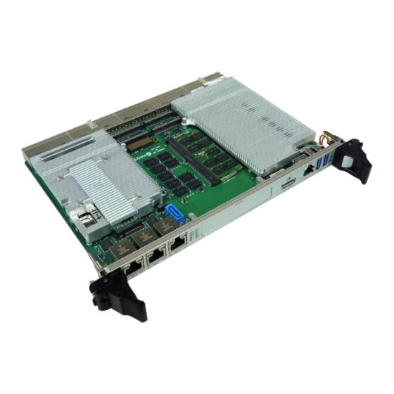
CP6007-SA, CP6007-RA – User Guide, Rev. 1.0 1.3.3. Board Layout Figure 3: 4 HP CP6007 Board Layout (Top View) Battery Magnetics M.2 NVME/SATA Module 22 x 40 Magnetics Magnetics PMC/XMC DP (J9) (J8) USB 3.0 (J7) USB 3.0 (J6) Hot Swap Switch & LED www.kontron.com... -
Page 19: Figure 4: 4 Hp Cp6007 Board Layout (Bottom View)
CP6007-SA, CP6007-RA – User Guide, Rev. 1.0 Figure 4: 4 HP CP6007 Board Layout (Bottom View) BIOS Adapter Socket www.kontron.com // 19... -
Page 20: Technical Specification
System Memory 32 GByte soldered RAM with ECC and data speed of up to 3200 MHz CP6007-SA only: 32 GByte SODIMM as additional option, dual channel DDR4 with ECC, up to 3200 MHz Flash Memory Sockets NVMe and SATA for alternative use, for M.2 2280 Solid State Drive ... - Page 21 CP6007-SA, CP6007-RA – User Guide, Rev. 1.0 Interfaces Gigabit Ethernet CP6007-SA Five 10 Base-T/100 Base-TX/1000 Base-T Gigabit Ethernet interfaces based on two Intel® I210-IT Gigabit Ethernet controllers, one Intel® I219 Gigabit Ethernet controller and one Intel® I350 quad-port Gigabit Ethernet controller (only two ports used): ...
- Page 22 CP6007-SA, CP6007-RA – User Guide, Rev. 1.0 Sockets Front Panel Connectors DisplayPort: one DP connector, J9 USB: two 4-pin, type A connectors, J6 and J7 Ethernet: three 8-pin, RJ-45 connectors, J10, J11 and J12 Serial port: one 8-pin, RJ-45 connector, J8 (COMA) ...
- Page 23 CP6007-SA, CP6007-RA – User Guide, Rev. 1.0 IPMI IPMI Controller NXP® ARM7 microcontroller with 512 kB firmware flash and automatic rollback strategy The IPMI controller carries out IPMI commands such as monitoring several onboard temperature conditions, board voltages and the power supply status, and managing hot swap operations.
- Page 24 CP6007-SA, CP6007-RA – User Guide, Rev. 1.0 Software (continued) IPMI Firmware IPMI firmware providing the following features: Keyboard Controller Style (KCS) interface Dual-port IPMB interface for out-of-band management and sensor monitoring IPMI over LAN (IOL) and Serial over LAN (SOL) support ...
-
Page 25: Compliance
Boards without conformal coating must not be exposed to a change of temperature which can lead to condensation. Condensation may cause irreversible damage, especially when the board is powered up again. Kontron does not accept any responsibility for damage to products resulting from destructive environmental testing www.kontron.com... -
Page 26: Related Publications
PICMG 2.1, Rev. 2.0 CompactPCI Hot Swap Specification IPMI - Intelligent Platform Management Interface Specification v2.0 IPMI Firmware User Guide Rev1.0, ID 1055-7522, General Information on the Kontron IPMI Firmware Kontron CompactPCI Backplane Manual, ID 24229 XMC Module ANSI/VITA 42.0-200x XMC Switched Mezzanine Card Auxiliary Standard ANSI/VITA 42.3-2006 XMC PCI Express Protocol Layer Standard... -
Page 27: 2/ Functional Description
Down Power Limit Reduction For further information about the processors used on the CP6007, please visit the Intel website. For further information concerning the suitability of other Intel processors for use with the CP6007, please contact Kontron. www.kontron.com // 27... -
Page 28: Graphics Controller
32 GByte soldered RAM with ECC and data speed of up to 3200 MHz Only qualified DDR4 ECC SODIMM modules from Kontron are authorized for use with the CP6007. Replacement of the SODIMM modules by the customer without authorization from Kontron will void the warranty. -
Page 29: Flash Memory
CP6007-SA, CP6007-RA – User Guide, Rev. 1.0 2.5. Flash Memory The CP6007 provides flash interfaces for the uEFI BIOS and a M.2 Flash module. 2.5.1. SPI Boot Flash for uEFI BIOS The CP6007 provides two 256 Mbit SPI boot flashes for two separate uEFI BIOS images, a standard SPI boot flash and a recovery SPI boot flash. -
Page 30: Board Interfaces
CP6007-SA, CP6007-RA – User Guide, Rev. 1.0 2.7. Board Interfaces 2.7.1. Front Panel LEDs The CP6007 provides three system status LEDs, one Hot Swap Status LED (HS LED), one temperature status LED (TH LED) and one Watchdog status LED (WD LED), as well as two IPMI LEDs (I0 and I1) and four General Purpose/POST code LEDs (LED3–0). -
Page 31: Table 6: Ipmi And Hs Leds' Functions
The General Purpose LEDs (LED3–0) are designed to indicate the boot-up POST code after which they are available to the application. If the LED3–0 are lit red during boot-up, a failure is indicated. In this event, please contact Kontron for further assistance. -
Page 32: Table 7: General Purpose Leds' Functions On The Cp6007
CP6007-SA, CP6007-RA – User Guide, Rev. 1.0 Table 7: General Purpose LEDs’ Functions on the CP6007 COLOR FUNCTION FUNCTION DURING uEFI BIOS POST FUNCTION DURING BOOT-UP (if POST code config. is enabled) AFTER BOOT-UP LED3 Power failure green uEFI BIOS POST bit 3 and bit 7... -
Page 33: Usb Interfaces
CP6007-SA, CP6007-RA – User Guide, Rev. 1.0 How to Read the 8-Bit POST Code Due to the fact that only 4 LEDs are available and 8 bits must be displayed, the POST code output is multiplexed on the General Purpose LEDs. -
Page 34: Serial Ports
CP6007-SA, CP6007-RA – User Guide, Rev. 1.0 2.7.4. Serial Ports The CP6007 provides two serial ports: COMA (RS-232) available either on the front panel or on the CompactPCI rear I/O interface COMB (RS-232/RS-422) on the CompactPCI rear I/O interface COMA and COMB are fully compatible with the 16550 controller. -
Page 35: Gigabit Ethernet
CP6007-SA, CP6007-RA – User Guide, Rev. 1.0 2.7.5. Gigabit Ethernet The CP6007-SA provides five Gigabit Ethernet interfaces. The CP6007-RA provides two further Gigabit Ethernet interfaces in addition to the five interfaces of the -SA variant. All Gigabit Interfaces are 10Base-T/100Base-T/1000Base-T compliant. -
Page 36: Sata Interfaces
CP6007-SA, CP6007-RA – User Guide, Rev. 1.0 2.7.6. SATA Interfaces The CP6007 provides six SATA ports: One SATA 6 Gb/s port on the J18 M.2 socket for mounting a SATA SSD M.2 module One SATA 6 Gb/s port on the standard SATA connector, J14, for connection to SATA devices via cable ... -
Page 37: Pmc Interface
CP6007-SA, CP6007-RA – User Guide, Rev. 1.0 2.7.8. PMC Interface The CP6007 provides one 3.3 V standard PMC interface with a dedicated 32-bit / 66 MHz PCI Express-to-PCI bridge. The PMC interface is compliant with the IEEE 1386.1-2001 specification, which defines a PCI electrical interface for the CMC (Common Mezzanine Card) form factor. -
Page 38: Compactpci Interface
CP6007-SA, CP6007-RA – User Guide, Rev. 1.0 2.7.10. CompactPCI Interface The CP6007 supports a flexibly configurable, hot swap CompactPCI interface. In the system slot the PCI / PCI-X interface is in the transparent mode, and in the peripheral slot the CompactPCI interface is isolated so that it cannot communicate with the CompactPCI bus. - Page 39 CP6007-SA, CP6007-RA – User Guide, Rev. 1.0 2.7.10.4. Hot Swap Support To ensure that a board may be removed and replaced in a working bus without disturbing the system, the following additional features are required: Power ramping Precharge ...
-
Page 40: Compactpci Connectors
J3, J4 and J5 with standard rear I/O interface functionality CP6007-SA provides 2x GbE on J3, CP6007-RA provides 4x GbE on J3 The CP6007 is designed for a CompactPCI bus architecture. The CompactPCI standard is electrically identical to the PCI local bus. -
Page 41: Table 14: Compactpci Bus Connector J1 System Slot Pinout
CP6007-SA, CP6007-RA – User Guide, Rev. 1.0 2.7.11.2. CompactPCI Connectors J1 and J2 Pinout The CP6007 is provided with two 2 mm x 2 mm pitch female CompactPCI bus connectors, J1 and J2. Table 14: CompactPCI Bus Connector J1 System Slot Pinout... -
Page 42: Table 15: Compactpci Bus Connector J1 Peripheral Slot Pinout
CP6007-SA, CP6007-RA – User Guide, Rev. 1.0 Table 15: CompactPCI Bus Connector J1 Peripheral Slot Pinout 3.3V V(I/O) 3.3V 3.3V 3.3V V(I/O) 3.3V 3.3V 3.3V IPMB SCL IPMB SDA V(I/O) 3.3V BDSEL# 14-12 Key Area 3.3V V(I/O) CPCI_Present# 3.3V RST#**... -
Page 43: Table 16: 64-Bit Compactpci Bus Connector J2 System Slot Pinout
CP6007-SA, CP6007-RA – User Guide, Rev. 1.0 Table 16: 64-bit CompactPCI Bus Connector J2 System Slot Pinout CLK6 CLK5 IPMB2_SDA IPMB2_SCL IPMB2_Alert PRST# REQ6# GNT6# DEG# FAL# REQ5# GNT5# AD[35] AD[34] AD[33] AD[32] AD[38] V(I/O) AD[37] AD[36] AD[42] AD[41] AD[40]... -
Page 44: Table 17: 64-Bit Compactpci Bus Connector J2 Peripheral Slot Pinout
CP6007-SA, CP6007-RA – User Guide, Rev. 1.0 Table 17: 64-bit CompactPCI Bus Connector J2 Peripheral Slot Pinout IPMB2_SDA IPMB2_SCL IPMB2_Alert DEG# FAL# V(I/O) V(I/O) V(I/O) V(I/O) V(I/O) V(I/O) SYSEN# A * indicates that the signal normally present at this pin is disconnected from the CompactPCI bus when the CP6007 is inserted in a peripheral slot. -
Page 45: Table 18: 64-Bit Compactpci Rear I/O Connector J3 Pinout For Cp6007-Sa
For the system rear I/O feature a special backplane is necessary. The CP6007 with rear I/O is compatible with all standard 6U CompactPCI passive backplanes with rear I/O support. The CP6007 conducts all standard rear I/O signals through the J3, J4 and J5 connectors. Table 18: 64-bit CompactPCI Rear I/O Connector J3 Pinout for CP6007-SA RIO_VCC RIO_VCC RIO_3.3V... -
Page 46: Table 19: Compactpci Rear I/O Connector J3 Signals For Cp6007-Sa
CP6007-SA, CP6007-RA – User Guide, Rev. 1.0 Table 19: CompactPCI Rear I/O Connector J3 Signals for CP6007-SA The RIO_XXX signals are power supply OUTPUTS to supply the rear I/O module with power. These pins MUST NOT be connected to any other power source, either within the backplane itself or within a rear I/O module. -
Page 47: Table 21: Compactpci Rear I/O Connector J3 Signals For Cp6007-Ra
CP6007-SA, CP6007-RA – User Guide, Rev. 1.0 Table 21: CompactPCI Rear I/O Connector J3 Signals for CP6007-RA SIGNAL DESCRIPTION COMA signaling (RS-232) COMB signaling (RS-422/RS-232) Graphic signaling USB0 to USB3 USB port signaling SPEAKER Standard PC speaker Fan speed sensoring... -
Page 48: Table 22: 64-Bit Compactpci Rear I/O Connector J4 Pinout
CP6007-SA, CP6007-RA – User Guide, Rev. 1.0 Table 22: 64-bit CompactPCI Rear I/O Connector J4 Pinout PIM:1 PIM:3 PIM:2 PIM:4 PIM:5 PIM:7 PIM:6 PIM:8 RIO_5V RIO_3.3V PIM:9 PIM:11 PIM:10 PIM:12 PIM:13 PIM:15 PIM:14 PIM:16 PIM:17 PIM:19 PIM:18 PIM:20 PIM:21 PIM:23... -
Page 49: Table 23: Compactpci Rear I/O Connector J5 Pinout
CP6007-SA, CP6007-RA – User Guide, Rev. 1.0 Table 23: CompactPCI Rear I/O Connector J5 Pinout GPI3 PWM1:OUT PWM2:OUT BATT (3.0V) SYS_WP# GPO0 GPO1 HDMI2:D0+ HDMI2:D0- HDMI2:D2+ HDMI2:D2- HDMI2:D1+ HDMI2:D1- HDMI2:HPDET GPO2 GPO3 HDMI2:CLK+ HDMI2:CLK- HDMI2:SDA HDMI2:SDC HDMI1:D0+ HDMI1:D0- HDMI1:D1+ HDMI1:D1-... -
Page 50: 3/ Configuration
CP6007-SA, CP6007-RA – User Guide, Rev. 1.0 3/ Configuration 3.1. DIP Switch Configuration The DIP switches SW3 and SW4 are located near the front panel at the bottom side of CP6007. Figure 8: Location of DIP Switch SW3 and SW4 3.1.1. -
Page 51: Dip Switch Sw4
The CP6007 provides write protection for non-volatile memories via the DIP switch SW3, the uEFI Shell and a backplane pin. If one of these sources is enabled, the system is write protected. Please contact Kontron for further information before using these functions. -
Page 52: Write Protection Register (Wprot)
CP6007-SA, CP6007-RA – User Guide, Rev. 1.0 3.3.1. Write Protection Register (WPROT) The Write Protection Register holds the write protect signals for non-volatile devices. Table 28: Write Protection Register (WPROT) ADDRESS 0x284 NAME Reserved SFWP DSWP BSWP SSWP ACCESS RESET... -
Page 53: Reset Status Register (Rstat)
CP6007-SA, CP6007-RA – User Guide, Rev. 1.0 3.3.2. Reset Status Register (RSTAT) The Reset Status Register is used to determine the host’s reset source. Table 29: Reset Status Register (RSTAT) ADDRESS 0x285 NAME PORS Reserved SRST Reserved IPRS FPRS CPRS... -
Page 54: Board Id High Byte Register (Bidh)
CP6007-SA, CP6007-RA – User Guide, Rev. 1.0 3.3.3. Board ID High Byte Register (BIDH) Table 30: Board ID High Byte Register (BIDH) ADDRESS 0x288 NAME BIDH ACCESS RESET 0xB4 BITFIELD DESCRIPTION 7..0 BIDH Board identification: CP6007-SA: 0xB4C0 CP6007-RA: 0xB4C1 3.3.4. -
Page 55: Watchdog Timer Control Register (Wtim)
CP6007-SA, CP6007-RA – User Guide, Rev. 1.0 3.3.5. Watchdog Timer Control Register (WTIM) Table 32: Watchdog Timer Control Register (WTIM) ADDRESS 0x28C NAME WEN/WT ACCESS RESET 0000 BITFIELD DESCRIPTION Watchdog timer expired status bit: 0 = Watchdog timer has not expired 1 = Watchdog timer has expired. -
Page 56: Board Id Low Byte Register (Bidl)
CP6007-SA, CP6007-RA – User Guide, Rev. 1.0 3.3.6. Board ID Low Byte Register (BIDL) Table 33: Board ID Low Byte Register (BIDL) ADDRESS 0x28D NAME BIDL ACCESS RESET 0xC0 (CP6007-SA) / 0xC1 (CP6007-RA) BITFIELD DESCRIPTION BIDL Board identification: CP6007-SA: 0xB4C0... -
Page 57: Led Control Register (Lctrl)
CP6007-SA, CP6007-RA – User Guide, Rev. 1.0 3.3.8. LED Control Register (LCTRL) The LED Control Register enables the user to switch on and off the front panel General Purpose LEDs. Table 35: LED Control Register (LCTRL) ADDRESS 0x291 NAME LCMD... -
Page 58: General Purpose Input Register (Gpin)
CP6007-SA, CP6007-RA – User Guide, Rev. 1.0 3.3.10. General Purpose Input Register (GPIN) The General Purpose Input Register holds the general purpose input signals of the rear I/O CompactPCI connectors. Table 37: General Purpose Input Register (GPIN) ADDRESS 0x293 NAME... -
Page 59: 4/ Power Considerations
CP6007-SA, CP6007-RA – User Guide, Rev. 1.0 4/ Power Considerations 4.1. System Power The considerations presented in the chapters below must be taken into account by system integrators when specifying the CP6007 system environment. 4.1.1. CP6007 Voltage Ranges The CP6007 has been designed for optimal power input and distribution. Still it is necessary to observe certain criteria essential for application stability and reliability. - Page 60 CP6007-SA, CP6007-RA – User Guide, Rev. 1.0 4.1.2.1. Start-Up Requirement Power supplies must comply with the following guidelines, in order to be used with the CP6007: Beginning at 10% of the nominal output voltage, the voltage must rise within > 0.1 ms to < 20 ms to the specified regulation range of the voltage.
-
Page 61: Power Consumption
4.2. Power Consumption The goal of this description is to provide a method to calculate the power consumption for the CP6007-SA or CP6007- RA baseboard and for additional configurations. The processor and the memory dissipate the majority of the thermal power. -
Page 62: Power Consumption Of The Cp6007-Sa Accessories
Total 50.8 W 40.9 W 4.2.1. Power Consumption of the CP6007-SA Accessories The following table indicates the power consumption of the CP6007-SA accessories. Table 43: Power Consumption of CP6007-SA Accessories POWER CONSUMPTION POWER 5 V POWER 3.3 V DDR4 32GB SO-DIMM approx. -
Page 63: Power Consumption Per Gigabit Ethernet Port
XMC modules are based on 3.3 V power along with variable power (VPWR) defined as either 5 V or 12 V in the ANSI/VITA 42.0-200x XMC Switched Mezzanine Card Auxiliary Standard specification. On the CP6007-SA, the VPWR is configured to 5 V. -
Page 64: 5/ Thermal Considerations
An airflow of 2.0 m/s to 3.0 m/s or a volumetric flow rate of 15 CFM to 20 CFM is a typical value for a standard Kontron ASM rack. For other racks or housings the available airflow will differ. The maximum ambient operating temperature must be determined for such environments. -
Page 65: Figure 9: Ambient Temperature For Xeon® W-11865Mre, Measured By Intel Ptu Tool For Broadwell-De Rev. 1.1
CP6007-SA, CP6007-RA – User Guide, Rev. 1.0 Figure 9: Ambient Temperature for Xeon® W-11865MRE, measured by Intel PTU Tool for Broadwell-DE rev. 1.1 Workload all Cores 100%, incl. CPU Package Power 31W, Turbo off Recommended operating range „20W“ „26W“ „31W“... -
Page 66: Figure 10: Ambient Temperature For Xeon® W-11555Mre, Measured By Intel Ptu Tool For Broadwell-De Rev. 1.1
CP6007-SA, CP6007-RA – User Guide, Rev. 1.0 Figure 10: Ambient Temperature for Xeon® W-11555MRE, measured by Intel PTU Tool for Broadwell-DE rev. 1.1 Recommended operating range „15W“ „19W“ „25W“ www.kontron.com // 66... -
Page 67: Peripherals
Devices such as HDDs, SSDs, PMC modules, XMC modules which are directly attached to the CP6007-SA must also be capable of being operated at the temperatures foreseen for the application. It may very well be necessary to revise system requirements to comply with operational environment conditions. In most cases, this will lead to a reduction in the maximum allowable ambient operating temperature or even require active cooling of the operating environment. -
Page 68: 6/ Installation
6.2. General Instructions on Usage In order to maintain Kontron’s product warranty, this product must not be altered or modified in any way. Changes or modifications to the device, which are not explicitly approved by Kontron and described in this manual or received from Kontron’s Technical Support as a special handling instruction, will void your warranty. -
Page 69: Hot Swap Removal
CP6007-SA, CP6007-RA – User Guide, Rev. 1.0 6.3.2. Hot Swap Removal Prior to following the steps below, ensure that the safety requirements are met. When removing a board from the system, particular attention must be paid to the components that may be hot, such as heat sink, etc. -
Page 70: Installation Of Peripheral Devices
Prior to installation of a peripheral device, ensure that the safety requirements are met. Special attention must be paid to avoid touching any components that may be hot, such as heat sink, etc. Figure 11: CP6007-SA with M.2 card and heat sink installed Figure 12: CP6007-RA with M.2 card installed, without heat sink M.2 Connector... -
Page 71: Sata M.2 Module Installation
CP6007-SA, CP6007-RA – User Guide, Rev. 1.0 6.4.1. SATA M.2 Module Installation A SATA Flash module may be connected to the CP6007 via the onboard connector, J18. This optionally available module must be physically installed on the CP6007 prior to installation of the CP6007 in a system. During installation it is necessary to ensure that the SATA Flash module is properly seated in the onboard connector J18, i.e. -
Page 72: Figure 14: Removing A M.2 Card
CP6007-SA, CP6007-RA – User Guide, Rev. 1.0 6.4.1.2. Removing a M.2 Card To remove a M.2 card: Power off the board, and then detach the power cord from the power supply. Remove the CP6007 board. Remove the 4x mounting screws and then remove the M.2 heat sink from the CP6007 Remove the screw securing the M.2 card. -
Page 73: Installation Of External Sata Devices
The CP6007 supports the installation of a PMC module via the J21 to J22 connectors. For information on the installation of the PMC module, refer to the documentation provided with the module. Figure 15: CP6007-SA with PMC/XMC Module installed (marked red) 6.4.4. -
Page 74: 7/ Uefi Bios
7.1. Starting the uEFI BIOS The CP6007 is provided with a Kontron-customized, pre-installed and configured version of AMI Aptio V® uEFI BIOS (referred to as uEFI BIOS in this manual). AMI BIOS firmware is based on the unified Extensible Firmware Interface (uEFI) specification and the Intel®... -
Page 75: Setup Menus
CP6007-SA, CP6007-RA – User Guide, Rev. 1.0 7.2. Setup Menus The Setup utility features five menus listed in the selection bar at the top of the screen: Main Advanced Security Boot Save & Exit The Setup menu items are selectable via the <Left/Right> keys. The currently active menu and the currently active Setup item highlighted in white. -
Page 76: Advanced Setup Menu
CP6007-SA, CP6007-RA – User Guide, Rev. 1.0 7.2.2. Advanced Setup Menu Advanced The Setup menu provides sub-screens and functions for advanced configuration. Setting items on this screen to incorrect values may cause the system to malfunction. Table 49: Advanced Setup Menu Sub-Screens and Functions... -
Page 77: Security Setup Menu
If the system cannot be booted because neither the user password nor the supervisor password are known, refer to the chapter 3.1, for information about clearing the uEFI BIOS settings, or contact Kontron for further assistance. www.kontron.com... -
Page 78: Boot Setup Menu
CP6007-SA, CP6007-RA – User Guide, Rev. 1.0 7.2.4. Boot Setup Menu Boot The Setup menu lists the for boot device priority order, which is dynamically generated. Table 51: Boot Priority Order FUNCTION DESCRIPTION Boot configuration Setup Prompt Timeout Configures number of seconds to wait for setup activation key. -
Page 79: Exit Setup Menu
CP6007-SA, CP6007-RA – User Guide, Rev. 1.0 7.2.5. Exit Setup Menu The Setup Exit menu provides functions for handling changes made to the uEFI BIOS settings and the exiting of the setup program. Table 52: Exit Setup Menu Functions FUNCTION... -
Page 80: The Uefi Shell
EFI and Framework Open Source Community homepage (http://sourceforge.net/projects/efi- shell/files/documents/). Please note that not all shell commands described in the EFI Shell Command manual are provided by the Kontron uEFI BIOS. The uEFI Shell commands are not case-sensitive. Each uEFI Shell command is provided with a detailed online help that can be invoked by entering “<cmd>... -
Page 81: Kontron-Specific Uefi Shell Commands
CP6007-SA, CP6007-RA – User Guide, Rev. 1.0 7.3.2. Kontron-Specific uEFI Shell Commands The Kontron uEFI BIOS provides the following additional uEFI Shell commands related to the specific HW features of the Kontron board. Table 53: Kontron-Specific uEFI Shell Commands FUNCTION... -
Page 82: Uefi Shell Scripting
Kontron flash-stored startup script (see Kontron-Specific uEFI Shell Command kBootNsh) If there is no Kontron flash-stored startup script present, the uEFI-specified startup.nsh script is used. This script must be located on the root of any of the attached FAT formatted disk drive. - Page 83 CP6007-SA, CP6007-RA – User Guide, Rev. 1.0 To create a uEFI Shell environment variable, use the set uEFI Shell command as shown below: Shell> set wdt_enable on Shell> set wdt_enable : on Shell> reset The following sample start-up script shows the uEFI Shell environment variable wdt_enable used to control the Watchdog.
-
Page 84: Firmware Update
CP6007-SA, CP6007-RA – User Guide, Rev. 1.0 7.5. Firmware Update 7.5.1. Updating the uEFI BIOS 7.5.1.1. uEFI BIOS Fail-Over Mechanism The CP6007 has two SPI boot flashes programmed with the uEFI BIOS, a standard SPI boot flash and a recovery SPI boot flash. - Page 85 CP6007-SA, CP6007-RA – User Guide, Rev. 1.0 7.5.1.3. uEFI BIOS Recovery In case of the standard SPI boot flash being corrupted and therefore the board not starting up, the board can be booted from the recovery SPI boot flash if the DIP switch SW1, switch 2 is set to ON. For further information, refer to the Chapter 3.1, DIP Switch Configuration.
-
Page 86: Updating The Ipmi Firmware
CP6007-SA, CP6007-RA – User Guide, Rev. 1.0 7.5.1.4. Determining the Active Flash Sometimes it may be necessary to check which flash is active. On the uEFI BIOS, this information is available via the uEFI Shell commands: kBoardInfo and kSelectFlash. The kBoardInfo uEFI Shell command always displays the SPI flash information from which the uEFI BIOS was started. -
Page 87: 8/ Ipmi Firmware
Two flash banks with rollback capability: manual rollback or automatic in case of upgrade failure For general information on the Kontron IPMI Firmware, refer to the IPMI Firmware User Guide. 8.2. IPMI Firmware and KCS Interface Configuration Initially the default configuration of the IPMI firmware (KCS and IPMB interfaces) is: ... -
Page 88: Supported Ipmi And Picmg Commands
CP6007-SA, CP6007-RA – User Guide, Rev. 1.0 8.3. Supported IPMI and PICMG Commands 8.3.1. Standard IPMI Commands The following table shows an excerpt from the command list specified in the IPMI specification 2.0. The shaded table cells indicate commands not supported by the CP6007 IPMI firmware. - Page 89 CP6007-SA, CP6007-RA – User Guide, Rev. 1.0 COMMAND IPMI 2.0 NETFN KONTRON SUPPORT SPEC. ON IPMI SECTION CONTROLLER Master Write-Read 22.11 O / Yes Get Channel Cipher Suits 22.15 O / No Suspend/Resume Payload Encryption 24.3 O / Yes Set Channel Security Keys 22.25...
- Page 90 CP6007-SA, CP6007-RA – User Guide, Rev. 1.0 COMMAND IPMI 2.0 NETFN KONTRON SUPPORT SPEC. ON IPMI SECTION CONTROLLER Get SDR Repository Info 33.9 Storage O / Yes Get SDR Repository Allocation Info 33.10 Storage O / Yes Reserve SDR Repository 33.11...
-
Page 91: Picmg Commands
CP6007-SA, CP6007-RA – User Guide, Rev. 1.0 8.3.2. PICMG Commands The following table shows an excerpt from the command list specified in the PICMG 3.0 R 2.0 AdvancedTCA Base Specification and the PICMG AMC.0 Advanced Mezzanine Card Specification, R 1.0. The shaded table cells indicate commands not supported by the IPMI firmware. -
Page 92: Firmware Identification
1 … = Board in chassis slot 1… 15..16* Reserved * Bytes 13 through 16 are optional and defined by Kontron. Invoking the IPMI command Get Device ID returns among other information the following data: Manufacturer ID = 3A98h (Kontron IANA ID) ... -
Page 93: Device Locator Record
CP6007-SA, CP6007-RA – User Guide, Rev. 1.0 8.4.2. Device Locator Record The device ID string which can be found by reading the Device Locator Record (SDR Type 12h) contains the string “BMC:x ... x”. For example, invoking the “ipmitool” command ipmitool sdr list mcloc will return the device ID strings of all available boards. -
Page 94: Sensor List
CP6007-SA, CP6007-RA – User Guide, Rev. 1.0 8.6.1. Sensor List The following table indicates all sensors available on the CP6007. For further information on Kontron’s OEM-specific sensor types and sensor event type codes presented in the following table, refer to section “OEM Event/Reading Types”. - Page 95 CP6007-SA, CP6007-RA – User Guide, Rev. 1.0 SENSOR NUMBER / SENSOR TYPE (CODE) / Assertion Mask / DESCRIPTION LED I1 ID STRING EVENT/READING TYPE Deassertion Active / (CODE) Mask/ Reading Reading Mask Mask 13h / System ACPI Power State 7FFFh / 0000h /...
- Page 96 CP6007-SA, CP6007-RA – User Guide, Rev. 1.0 SENSOR NUMBER / SENSOR TYPE (CODE) / Assertion Mask / DESCRIPTION LED I1 ID STRING EVENT/READING TYPE Deassertion Active / (CODE) Mask/ Reading Reading Mask Mask 22h / Initialization Agent (C2h) / 0002h / 0000h / Initialization agent “digital”...
-
Page 97: Sensor Thresholds
CP6007-SA, CP6007-RA – User Guide, Rev. 1.0 8.7. Sensor Thresholds Table 58: Thresholds – Standard Temperature Range (CP6007-SA) and Extended Temperature Range (CP6007-RA) Sensor Number / 01h / 03h / 03h / ID String NNN:Temp CPU NNN:Temp Board NNN:Temp Board (0°C to +60°C) -
Page 98: Oem Event/Reading Types
CP6007-SA, CP6007-RA – User Guide, Rev. 1.0 8.8. OEM Event/Reading Types OEM (Kontron) specific sensor types and codes are presented in the following table. Table 60: OEM Event/Reading Types OEM SENSOR OEM EVENT/ DESCRIPTION TYPE (CODE) READING TYPE (CODE) Firmware Info 1 (C0h) -
Page 99: Ipmi Firmware Code
CP6007-SA, CP6007-RA – User Guide, Rev. 1.0 OEM SENSOR OEM EVENT/ DESCRIPTION TYPE (CODE) READING TYPE (CODE) e.g. for Event Sensor-specific Offset Power Good / Power Good Event HS fault# HS early fault# DEG# FAL# BDSELState 5h..6h n.a. vccMainGood 8h..Eh n.a. -
Page 100: 9/ Technical Support
CP6007-SA, CP6007-RA – User Guide, Rev. 1.0 9/ Technical Support For technical support contact our Support department: E-mail: support@kontron.com Phone: +49-821-4086-888 Make sure you have the following information available when you call: Product ID Number (PN), ... -
Page 101: Returning Defective Merchandise
RMA number. The buyer accepts responsibility for all freight charges for the return of goods to Kontron's designated facility. Kontron will pay the return freight charges back to the buyer's location in the event that the equipment is repaired or replaced within the stipulated warranty period. Follow these steps before returning any product to Kontron. -
Page 102: Appendix A: List Of Acronyms
CP6007-SA, CP6007-RA – User Guide, Rev. 1.0 Appendix A: List of Acronyms Table 61: List of Acronyms ACPI Advanced Configuration Power High Definition Audio (HD Audio) Interface HD/HDD Hard Disk /Drive Application Programming Interface HDMI High Definition Multimedia Interface Basic COM Express®... - Page 103 CP6007-SA, CP6007-RA – User Guide, Rev. 1.0 Serial Attached SCSI – high speed serial version of SCSI SATA Serial AT Attachment: SCSI Small Computer System Interface System Event Log ShMC Shelf Management Controller SMBus System Management Bus SO-DIMM Small Outline Dual in-line Memory...
-
Page 104: About Kontron
CP6007-SA, CP6007-RA – User Guide, Rev. 1.0 About Kontron Kontron is a global leader in IoT/Embedded Computing Technology (ECT). Kontron offers individual solutions in the areas of Internet of Things (IoT) and Industry 4.0 through a combined portfolio of hardware, software and services. With its standard and customized products based on highly reliable state-of-the-art technologies, Kontron provides secure and innovative applications for a wide variety of industries.
Need help?
Do you have a question about the CP6007-SA and is the answer not in the manual?
Questions and answers